oil MAZDA PROTEGE 1992 Workshop Manual
[x] Cancel search | Manufacturer: MAZDA, Model Year: 1992, Model line: PROTEGE, Model: MAZDA PROTEGE 1992Pages: 1164, PDF Size: 81.9 MB
Page 730 of 1164

R REAR SUSPENSION (STRUT)
Assembly
41-50)
N.m (m-kg, f&lb)
03UORX-041
!J ‘6
1. Shock absorber
2. Lower spring seat
3. Coil spring
4. Bound stopper
5. Stopper seat
03UORX.047
R-24
6. Mounting block
7. Retainer
8. Nut and washer
9. Cap
1. Secure the shock absorber in a vise.
Caution
l Use protective plates in the jaws of the vise.
2. Install the lower spring seat.
3. Install the coil spring, fitting the end of the coil into the step
of the lower seat.
4. Compress the coil spring with the SST.
5. Install the bound stopper and the stopper seat.
Page 731 of 1164

REAR SUSPENSION ~STRUT~
T LbWER BRACKET
LOWER BRACKET
23UQRX-02
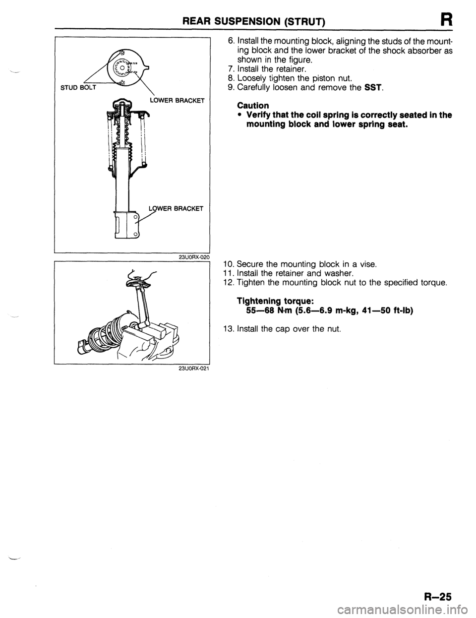
6. Install the mounting block, aligning the studs of the mount-
ing block and the lower bracket of the shock absorber as
shown in the figure.
7. Install the retainer.
8. Loosely tighten the piston nut.
9. Carefully loosen and remove the
SST.
Caution
l Verify that the coil spring is correctly seated In the
mounting block and lower spring seat.
IO. Secure the mounting block in a vise.
11. Install the retainer and washer.
12. Tighten the mounting block nut to the specified torque.
Tightening torque:
55-66 Narn (5.6-6.9 m-kg, 41-50 ft-lb)
13. Install the cap over the nut.
R-25
Page 737 of 1164

S
BODY
INDEX ........................................................ 2
HOOD ........................................................
COMPONENTS ........................................ t
FRONT FENDER PANEL .............................. ;I
COMPONENTS ........................................ S- ::
FRONT DOOR ............................................. S- 8
COMPONENTS ........................................ S- 8
FRONT SIDE WINDOW REGULATOR AND
GLASS ..................................................... s- 10
COMPONENTS ........................................ s- 10
FRONT DOOR LOCK AND OPENER .............. S- 13
COMPONENTS ........................................ s- 13
REAR DOOR ............................................... s- 15
COMPONENTS ........................................ s- 15
REAR SIDE WINDOW REGULATOR AND
GLASS ..................................................... s- 17
COMPONENTS ........................................ s- 17
REAR DOOR LOCK AND OPENER ...........
.-. ...
S- 19
COMPONENTS ........................................ s- 19
REAR HATCH ............................................. s- 20
COMPONENTS ........................................ s- 20
REAR HATCH LOCK AND OPENER.. .............
S- 22
COMPONENTS ........................................ s- 22
POWER DOOR LOCK SYSTEM.. ................... S- 23
STRUCTURAL VIEW .................................. S- 23
TROUBLESHOOTING GUIDE ...................... S- 24
DOOR LOCK SWITCH ............................... S- 28
DOOR LOCK CONTROL ............................ S- 26
DOOR LOCK TIMER AND RELAY ............... S- 26
POWER WINDOW SYSTEM .......................... S- 27
STRUCTURAL VIEW .................................. S- 27
TROUBLESHOOTING GUIDE.. .................... S- 28
MAIN POWER WINDOW SWITCH.. .............. S- 31
POWER WINDOW SUB-SWITCH.. ................ S- 32
POWER WINDOW MOTOR ......................... S- 32
TRUNK LID .................................................
s- 33
COMPONENTS ........................................ s- 33
TRUNK LID LOCK AND OPENER.. ................ S- 35
COMPONENTS ........................................ s- 35
FUEL FILLER LID AND OPENER ................... S- 37
COMPONENTS ........................................ s- 37
FRONT BUMPER ......................................... s- 39
COMPONENTS ........................................ s- 39
REAR BUMPER ........................................... s- 40
COMPONENTS ........................................ s- 40
REAR SPOILER ........................................... s- 41
COMPONENTS ........................................ s- 41
MOLDING, PROTECTOR, GARNISH .............. S- 42
UPPER WINDSHIELD MOLDING,
A-PILLAR GARNISH ................................ S- 42
REAR WINDOW MOLDING (PROTEGE) ........ S- 43
REAR WINDOW MOLDING (HATCHBACK) ... S- 44
ROOF MOLDING ...................................... S- 46
BELTLINE MOLDING ................................ S- 48
SIDE PROTECTOR.. .................................. S- 49
RADIATOR GRILLE, LOWER GRILLE
MOLDING ................................................. s- 51
COMPONENTS ........................................ S- 51
REAR FINISHER.. ........................................
S- 52
COMPONENTS ........................................ S- 52
COWL GRILLE ............................................ s- 53
COMPONENTS ........................................ s- 53
EXTRACTOR CHAMBER ..............................
COMPONENTS ........................................ g-
- ;; OUTSIDE MIRROR ....................................... s- 54
TROUBLESHOOTING GUIDE.. .................... S- 54
POWER OUTSIDE MIRROR SWITCH ............ S- 55
POWER OUTSIDE MIRROR.. ...................... S- 56
COMPONENTS ........................................ s- 66
WINDSHIELD .............................................. S- 58
PREPARATION ......................................... S- 58
COMPONENTS ........................................ S- 58
QUARTER WINDOW GLASS ......................... S- 62
COMPONENTS .................. ..T ................... S- 82
REAR WINDOW GLASS ............................... S- 63
PREPARATION ......................................... S- 63
COMPONENTS ........................................ S- 63
WINDSHIELD WIPER AND WASHER ............. S- 87
TROUBLESHOOTING GUIDE.. .................... S- 67
WIPER MOTOR ........................................ s- 70
WASHER MOTOR ..................................... s- 71
WINDSHIELD WIPER AND WASHER
SWITCH ................................................ s- 71
COMPONENTS ........................................ S- 72
REAR WIPER AND WASHER ........................ S- 74
TROUBLESHOOTING GUIDE.. .................... S- 74
REAR WIPER MOTOR ............................... s- 77
REAR WASHER MOTOR ............................ s- 77
REAR WIPER AND WASHER SWITCH.. ........ S- 77
COMPONENTS ........................................ S- 78
SLIDING SUNROOF ..................................... S- 80
TROUBLESHOOTING GUIDE.. .................... S- 80
MOTOR ASSEMBLY .................................. S- 81
SUNROOF RELAY .................................... S- 82
SUNROOF SWITCH
(OVERHEAD CONSOLE) .......................... S- 82
COMPONENTS ........................................ S- 83
HEADLINER ................................................ S- 89
COMPONENTS ........................................ S- 89
DASHBOARD .............................................. s- 94
COMPONENTS ........................................ s- 94
TRIM .......................................................... s- 97
COMPONENTS ........................................ s- 97
FLOORMAT ................................................ s- 99
COMPONENTS ........................................ s- 99
SEAT BELT ................................................ S-l 00
COMPONENTS ........................................ S-l 00
SEAT BELT .............................................. S-l 02
BUCKLE SWITCH ..................................... s-102
PASSIVE SHOULDER BELT SYSTEM.. .......... S-103
STRUCTURAL VIEW .................................. s-103
TROUBLESHOOTING GUIDE.. .................... S-104
PASSIVE SHOULDER BELT MOTOR.. .......... S-106
DOOR CATCH SWITCH ............................. S-l 07
LIMIT SWITCH (FRONT/REAR)
WARNING SWITCH ....................................................... z-:X;
-
SPEED SENSOR ....................................... s-i 07
COMPONENTS ........................................ S-l 08
SEAT ......................................................... s-110
COMPONENTS ........................................ s-110
SEAT ASSEMBLY ..................................... S-l 13
UNDERBODY DIMENSIONS .............. ..: ......... S-116
PROJECTED DIMENSIONS (PROTEGE) ........ S-116
PROJECTED DIMENSIONS (HATCHBACK). .. S-117
STRAIGHT-LINE DIMENSIONS (PROTEGE). .. S-118
STRAIGHT-LINE DIMENSIONS
(HATCHBACK) ........................................ s-119
23UOSX.001
Page 739 of 1164

INDEX
1. Rear door
10. Rear bumper
Components ...............................
page S-l 5 Components ............................... page S-40
q 2. Rear side window regulator and glass
11. Rear spoiler
Components ...............................
page S-i 7 Components ............................... page S-41
3. Rear door lock and opener 12. Molding, protector, garnish
Components ...............................
page S-l 9 Rear window molding
4. Rear hatch (PROTEGE) ............................... page S-43
Components ............................... page S-20 Rear window molding
5. Rear hatch lock and opener (Hatchback) .............................. page S-44
Components ...............................
page S-22 Side protector ............................. page S-49
6. Power door lock system 13. Rear finisher
Structural view ............................
page S-23 Components ............................... page S-52
Troubleshooting guide.. .............. page S-24 14. Extractor chamber
Door lock switch.. .......................
page S-26 Components ................................ page S-53
Door lock control.. ...................... page S-26 15. Quarter window glass
Door lock timer and relay ...........
page S-26 Components ............................... page S-62
7. Power window system
16. Rear window glass
Structural view ............................
page S-27 Components ............................... page S-63
Troubleshooting guide.. .............. page S-28 17. Rear wiper and washer
Main power window switch.. ...... page S-31 Troubleshooting
guide.. .............. page S-74
Power window sub-switch ..........
page S-32 Rear wiper motor.. ...................... page S-77
Power window motor.. ................
page S-32 Rear washer motor.. ................... page S-77
8. Trunk lid Rear wiper and washer switch..
. page S-77
Components ...............................
page S-33 Components
............................... page S-78
9. Trunk lid lock and opener
Components ...............................
page
S-35
s-3
Page 777 of 1164

REAR SPOILER S
REAR SPOILER
COMPONENTS
Removal / Installation
1. Disconnect the negative battery cable.
2. Remove in the order shown in the figure.
3. Install in the reverse order of removal.
1. Rear spoiler assembly
03uosx-055
s-41
Page 866 of 1164

T
ELECTRICAL SYMBOLS
Switches and Relays OUTLINE
There is an NC (normally closed) and NO (normally open) indication for switches and relays which shows
when no change of operation conditions has occurred.
Relay Switch
NO type relay NC type relay NO switch NC switch
Not in operation
(No power supply) +E+ #Fig -o-- -da--
ax ax
STOP
FLOW STOP FLOW
In operation
(Power supply) * !jiij! kiig 6 dLe
cw r”X
FLOW STOP FLOW STOP
Other Electrical Symbols
BATTERY
THERMISTER DIODE CONDENSER
Q
M
MOTOR I
T-10
l-
BODY GROUND
COIL, SOLENOID i
0 8 HOLDER BOX
FUSE
RESISTOR
1
T
FUSIBLE LINK
1 i 1
VARIABLE RESISTOR
LIGHT
HEATER
69G15X-O(
Page 895 of 1164

EXTERIOR LIGHTING SYSTEM T
Stoplight
Circuit diaaram
GTOPLIGHTS F-2
SHIFT-LOCK
BLUB TRADE NUMBER
STOPLIGHT: 1157 (27W)
HIGH MOUNT
STOPLIGHT: 921 (18.4W) G (F) *ENGINE CONTROL UNIT
(SECTION B- lc;26)
G (F) *CRUISE CONTROL UNIT
(SECTION 01)
WITH REAR SPOILER
HIGH MOUNl-
STOPLIGHT
STOPLIGHT STOPLIGHT
-06 STOPLIGHT
SWITCH (F) F-07 HIGH MOUNT STOP-E-12 STOPLIGHT LH(R) E-13 STOPLIGHT RH(R)
LIGHT (R3)
WITH
REAR SPOILER---+ (R2)
03UOTX-057
T-39
Page 901 of 1164

EXTERIOR LIGHTING SYSTEM T
HIGH-MOUNT STOPLIGHT
Removal / Inspection / Installation
1. Remove in the order shown in the figure.
2. Inspect all parts and repair or replace as necessary.
3. Install in the reverse order of removal.
PROTEGE (With rear sDoiler1 . ,
1. Screw
2. Lens
PROTEGe (Without rear spoiler)
3. Bulb
Visual inspection
1. Fastener
2. Cover 3. Bolt
4. Lens 5.Bulb
Visual inspection
6. Bolt
7. Bracket
T-45
Page 916 of 1164

2L BUZZER 2A 28 2C 20 1A 3K - - -
n n n n n
nn
1 1
1
BELTS
OIL
3w
3W
u u uuu u u u u
L-l u u u u
1C 3L 2E 2G 11
1G 1F 1D 1B
3F 38 3G 1E 30
n II 11 l-l l-l It 11 l-l
1J 11 1H 1G IF 1E 1D lG 1B 1A 2L 2K 2J 21 2H 2G 2F 2E 20 2G 28 2A
n Ir ,I
3L 3K 3J 31 3i-l 3G 3F 3E 3,, 3~ 3B 3A
Ter-
minal Connected to
tA Combination switch
1B Ground
1C Fuel tank unit
ID EGI control unit
1E Washer level sensor
1F Fuel tank unit
1G EC-AT control unit
1H EC-AT control unit
II
1J I Connected to Ter-
minal
2A Speed sensor output
28 Light switch (high beam)
2C Turn switch (L1
Page 917 of 1164

WARNING SYSTEM T
13UOTX-07
63U15X-05
, I//
‘nF -
-
-
FUEL
13UOTX.08C
- CHARGE
13UOTX-08
13UOTX-08
Inspection
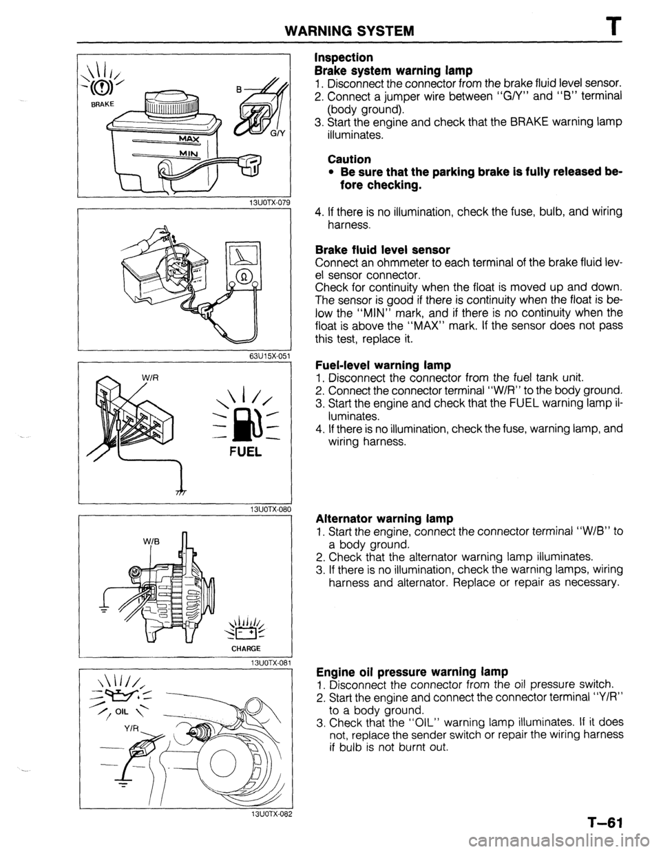
Brake system warning lamp
1. Disconnect the connector from the brake fluid level sensor.
2. Connect a jumper wire between “G/Y” and “6” terminal
(body ground).
3. Start the engine and check that the BRAKE warning lamp
illuminates.
Caution
l Be sure that the parking brake is fully released be-
fore checking.
4. If there is no illumination, check the fuse, bulb, and wiring
harness.
Brake fluid level sensor
Connect an ohmmeter to each terminal of the brake fluid lev-
el sensor connector.
Check for continuity when the float is moved up and down.
The sensor is good if there is continuity when the float is be-
low the “MIN” mark, and if there is no continuity when the
float is above the “MAX” mark. If the sensor does not pass
this test, replace it.
Fuel-level warning lamp
1. Disconnect the connector from the fuel tank unit.
2. Connect the connector terminal “W/R” to the body ground.
3. Start the engine and check that the FUEL warning lamp il-
luminates.
4. If there is no illumination, check the fuse, warning lamp, and
wiring harness.
Alternator warning lamp
1. Start the engine, connect the connector terminal “W/B” to
a body ground.
2. Check that the alternator warning lamp illuminates.
3. If there is no illumination, check the warning lamps, wiring
harness and alternator. Replace or repair as necessary.
Engine oil pressure warning lamp
1. Disconnect the connector from the oil pressure switch.
2. Start the engine and connect the connector terminal “Y/R”
to a body ground.
3. Check that the “OIL” warning lamp illuminates. If it does
not, replace the sender switch or repair the wiring harness
if bulb is not burnt out.
T-61