light MAZDA PROTEGE 1992 Repair Manual
[x] Cancel search | Manufacturer: MAZDA, Model Year: 1992, Model line: PROTEGE, Model: MAZDA PROTEGE 1992Pages: 1164, PDF Size: 81.9 MB
Page 579 of 1164

TRANSAXLE J2
Clutch Housing and Transaxle Case Components
1. Select the adjust shim(s), referring to Bearing Preload Adjustment.
2. Assemble in the order shown in the figure, referring to Assembly Note.
3. Verify that the bearing preload is satisfied after assembly, referring to Bearing Preload.
-s
APPLY SPECIFIED OIL TO INDIVIDUAL PARTS EXCEPT SWITCHES
&II N.m (SO-110 cm-kg, SO-95 In-lb)
20-29
P-3,
@NEW=
O-RING, I
14-22) 11
R N.m (120-160 cm-kg,
104-l 39 in-lb)
A
=SELECTlVE ROLL PIN NE
(120-140 cm-kg,
SELECTIVE 20-29 (2-3, 14-22)
N.m (m-kg,
??I 1
1. Change rod 16. Oil seal
2. Joint
3. Oil passage
4. Back-up light switch
5. Oil seal
Assembly Note . . . . . . . . . . . . . . . . . . . . . . . . . . page J2-35
6. Adjust shim(s)
Bearing preload adjustment . . . . . page J2-32
Bearing preload . . . . . . . . . . . . . . . . . . . . . . . . page J2-36
7. Bearing outer race
8. Adjust shims
Bearing preload adjustment . . . . . page J2-32
Bearing preload . . . . . . . . . . . . . . . . . . . . . . . . page J2-36
9. Diaphragm springs
Assembly Note . . . . . . . . . . . . . . . . . . . . . . . . . . page J2-35 Assembly Note . . . . . . . . . . . . . . . . . . . . . . . . . . page J2-35
17. Gear case
18. Driven gear
19. Speedometer driven gear assembly
20. Bleeder
21. Bleeder cover assembly
22. Oil seal
23. Selector
24. Reverse gate
25. Spring
26. Boot
Assembly Note ,.,....................... page J2-35
27. Change rod assembly
28. Roll pin
10. Bearing outer races
11. Neutral switch and gasket
12. Drain plug and washer
13. Reverse lever
14. Reverse lever shaft
15. Bearing outer race 29. Change arm
30. Guide plate
31, Funnel
32. Bearing outer race
33. Oil seal
34. Bearing outer race
J2-31
Page 589 of 1164

TRANSAXLE J2
INSTALLATION
1. Raise the vehicle and support it with safety stands.
2. Install in the order shown in the figure, referring to
Installation Note,
3. Fill the transaxle with the specified amount of the specified transaxle oil after installation.
4. Warm up the engine and transaxle, and inspect for oil leakaae and transaxle ooeration.
37-52 (3.8-5.3, 27-38) 37-52 (3.8-5.3, 27-38)
9.8-12 (1.0-1.2, 7.2-8.7)
7.8-l 2 (0.8-l .2, 5.8-8.7)
1. Transaxle
6. Tie-rod end
2. Engine mount No.4 7. Clutch release cylinder
3. Joint shaft
8. Engine mount No.2
4. Driveshaft
9. Exhaust pipe
Installation Note
10. Engine mount member
. . . . . . . . . . . . . . . . . . . . .
page J2-42 11. Control rod
5. Stabilizer
12. Extension bar
Installation Note 13. Starter
. . . . . . . . . . . . ..______. page J2-42 14. Ground
31-48 (3.2-4. ‘8
88-l 18 (g-12,65-87)
(6.5-9.1, 47-88)
37-52 (3.8-5.3, 27-38)
N.m (m-kg, Mb)
15. Neutral switch connector
16. Back-up light switch
connector
17. Speedometer
cable
18. Battery carrier
19. Battery
20. Air hose and resonance
chamber
21. Splash shield
22. Wheel and tire
52-41
Page 624 of 1164

DRIVE SHAFT
8. Apply the specified grease included in the kit to the tripod
joint, outer ring, and boot. Install the outer ring.
9. If the wheel-side boot was removed, fill with the specified
grease included in the kit.
Specified grease
!J@z)
B6 SOHC BP SOHC BP DOHC
Right Left Right
Left Right Left
side side side side side side
DIFFEREN- 2;&y’ 140 (4.94) 145 (5.12)
TIAL SIDE y;L44;)
YELLOW YELLOW YELLOW
WHEEL SIDE 70 (2.47) 140 (4.94) 90 (3.18)
BLACK BLACK BLACK
23UOMX-03
I I
I
23UOMX-0:
M-28
Caution
l Be sure the boots are not dented or twisted.
. Carefully lift up the small end of the boots to release
any trapped air.
10. Install the boots.
11. Measure the length of the drive shaft.
Standard length: mm (in)
B6 SOHC BP SOHC BP DOHC
MTX 1 ATX MTX 1 ATX MTX 1 ATX
light side 919.3 918.7
630.7
(36.19) (36.17) (24.83)
640.2 621.2 637.1
(25.20) (24.46) (25.08)
I Left side
I 637.8
(25.11)
12. Fold the new bands back by pulling on the ends with pliers.
13. Lock the ends of the bands by bending the locking clips.
Page 674 of 1164

P CONVENTIONAL BRAKE SYSTEM
03UOPX.01
03UOPX-01
03UOPX-01
23UOPX-0
BRAKE FLUID
Inspection
Leakage inspection
Depress the brake pedal several times, and inspect for leak-
age of the brake line system. __,
Brake Fluid Level
Leakage check
Verify that the fluid level in the reservoir is between the MAX
and MIN lines on the reservoir.
Add fluid if it is below MAX.
Replacement
1. Follow the procedure outlined in Air Bleeding.
(Refer to page P-6).
2. Continue bleeding and replacing the brake fluid until only
clean fluid is expelled.
3. Fill the reservoir to the MAX level.
BRAKEPEDAL
Inspection, On-vehicle
Brake pedal height
Inspection
Verify that the distance from the center on the pedal pad to
the floor mat is as specified.
Specification: 193-196mm (7.60-7.72 in)
Adjustment
1. Disconnect the stoplight switch connector.
2. Loosen locknuts @J and turn switch @ until it does not con-
tact the pedal.
3. Loosen locknuts (I?J and turn rod @ to adjust the height
of the brake pedal.
4. Tighten the stoplight switch until it contacts the pedal; then
turn it an additional 112 turn. Tighten locknuts @ and @I.
5. Connect the stoplight switch connector.
6. Verify operation of the stoplights.
P-8
Page 675 of 1164

CONVENTIONAL BRAKE SYSTEM
03UOPX-021
PEDAL-TO-FLOOR
CLEARANCE
03UOPX-02
Pedal Play
Inspection
1. Depress the pedal a few times to eliminate the vacuum in
the system.
2. Gently depress the pedal by hand and check the free play
(until resistance is felt).
Pedal play: 4-7mm (0.16-0.26 in)
Adjustment
1. Loosen locknut @and turn rod @to adjust the free play.
2. Verify the pedal height and the stoplight operation.
Pedal-To-Floor Clearance
Inspection
Verifv that the distance from the floor panel to the center of
the pedal pad is as specified when the pedal is depressed
with a force of 569 N (60
kg, 132 lb).
Pedal-to-floor clearance: 70mm (2.76 in) min.
If the distance is less than specified, check for the following
problems:
1. Air in brake system
2. Malfunction of automatic adjuster (Rear drum brakes)
3. Worn shoes or pads
P-9
Page 679 of 1164

CONVENTIONALBRAKESYSTEM P
1 SUOPX-001
03UOPX-03
0
o3uoPx-os
0
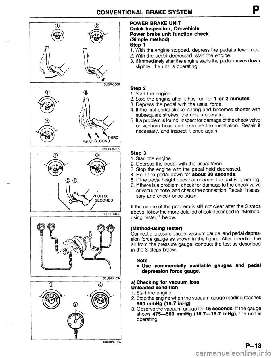
POWER BRAKE UNIT
Quick Inspection, On-vehicle
Power brake unit function check
k:;;p{e method)
1. With the engine stopped, depress the pedal a few times.
2. With the pedal depressed, start the engine.
3. If immediately after the engine starts the pedal moves down
slightly, the unit is operating.
Step 2
1. Start the engine.
2. Stop the engine after it has run for
1 or 2 minutes.
3. Depress the pedal with the usual force.
4. If the first pedal stroke is long and becomes shorter with
subsequent strokes, the unit is operating.
5. If a problem is found, inspect for damage of the check valve
or vacuum hose and examine the installation. Repair if
necessary, and inspect it once again.
Step 3
1. Start the engine.
2. Depress the pedal with the usual force.
3. Stop the engine with the pedal held depressed.
4. Hold the pedal down for
about 30 seconds.
5. If the pedal height does not change, the unit is operating.
6. If there is a problem, check for damage to the check valve
or vacuum hose, and check the connection. Repair if neces-
sary and check once again.
If the nature of the problem is still not clear after the 3 steps
above, follow the more detailed check described in “Method-
using tester,” below.
(Method-using tester)
Connect a pressure gauge, vacuum gauge, and pedal depres-
sion force gauge as shown in the figure. After bleeding the
air from the pressure gauge, conduct the test as described
in the 3 steps below.
Note
l Use commercially available gauges and pedal
depression force gauge.
a) Checking for vacuum loss
Unloaded condition
1. Start the engine.
2. Stop the engine when the vacuum gauge reading reaches
500 mmHg (19.7 inHg).
3. Observe the vacuum gauge for 15 seconds. If the gauge
shows 475-500
mmHg (18.7-19.7 inHg), the unit is
operating.
P-13
Page 710 of 1164

R OUTLINE
OUTLINE
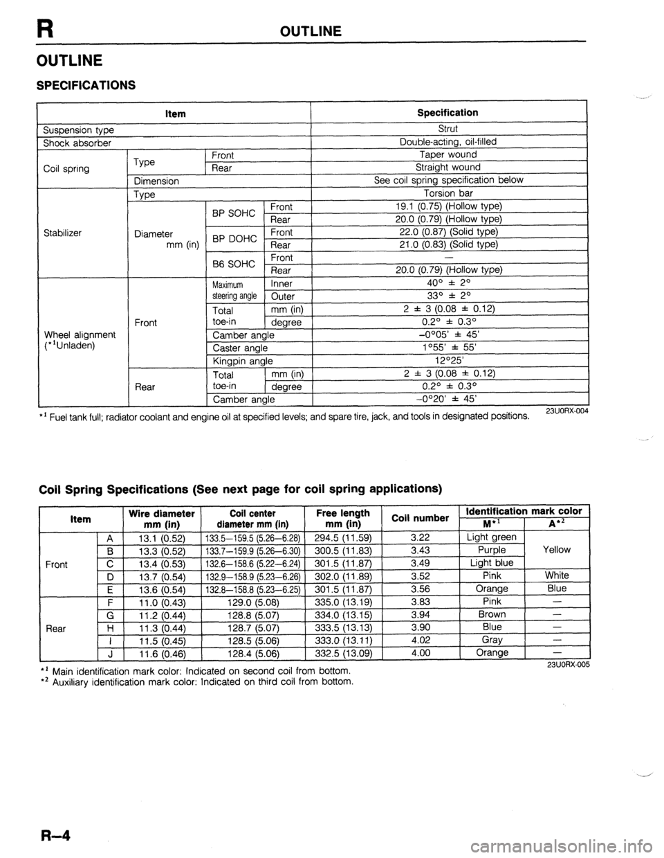
SPECIFICATIONS
Suspension type Item Specification Strut
Shock absorber Double-acting, oil-filled
Coil spring
Stabilizer Type Front Taper wound
Rear Straight wound
Dimension See coil spring specification below
Type Torsion bar
BP SOHC Front 19.1 (0.75) (Hollow type)
Rear 20.0 (0.79) (Hollow type)
Diameter 22.0 (0.87) (Solid type)
mm (in) BP DOHC ;eTrt
21 .O (0.83) (Solid type)
P ,
-
66 SOHC rronr
Rear 20.0 (0.79) (Hollow type)
Maximum Inner 400 f 20
steering angle
Outer 330 f 20
Total mm (in) 2 f 3 (0.08 f 0.12)
Front toe-in
degree 0.2O f 0.3O
Wheel alignment
(*‘Unladen) Camber angle -0005’ f 45’
Caster angle 1055 * 55’
Kingpin angle 12O25’
Total mm (in) 2 f 3 (0.08 * 0.12)
Rear toe-in
degree 0.2O f 0.3O
Camber angle -0°20’ f 45’
*’ Fuel tank full; radiator coolant and engine oil at specified levels; and spare tire, jack, and tools in designated positions.
23UORX.004
Coil Spring Specifications (See next page for coil spring applications)
I Item Wire diameter Coil center Free lel.=-. .
mm iin1 rliamotor mm [in mm (in 1 coil numbs
Front
nath
1 _ . . *St Identification mark color +l
., . . . . I...,
-*.....-.“, * . . . . . ,..-, -....- I--‘, M iA*=
A 13.1 (0.52) 133.5-159.5 (5.26-6.28)
294.5 (11.59) 3.22 Light green
B 13.3 (0.52) 133.7-159.9 (5.26-6.30) 300.5 (11.83)
3.43 Purple Yellow
C 13.4 (0.53)
132.6-158.6 (5.22-6.24) 301.5 (11.87) 3.49
Light blue
D 13.7 (0.54)
132.9-158.9 (5.23-6.26) 302.0 (11.89) 3.52
Pink White
I F I 12f3 Kl5Al I 1.17 A-l!% 8 f!i PR-Fi 751
I RrIl .5 II 1 6x71 I 3.56 Orange
Blue
3 83 Pink -
Brown - .“._ \“.- .,
. “W.., ~ - -. - \-. -- -. - -, -- .-
\’ .‘-‘I t
F 11 .o (0.43) 129.0 (5.08)
335.0 (13.19) -.--
G 11.2 (0.44) 128.8 (5.07)
334.0 (13.15) 3.94
Rnnr l-4
1 I ? 07 AA 1387 /5n7
.?m !i 113 1% 3 an Blue - I I I I .” \v.-7, I&V., \V.“., ---.., \.-. .-, I 11.5 (0.45) 128.5 (5.06)
333.0 (13.11) i:oi Gray
-
J 11.6 (0.46) 128.4 (5.06)
332.5 (13.09) 4.00 Orange
-
l ’ Main identification mark color: Indicated on second coil from bottom.
*’ Auxiliary identification mark color: Indicated on third coil from bottom. 23UORX-005
R-4
Page 743 of 1164

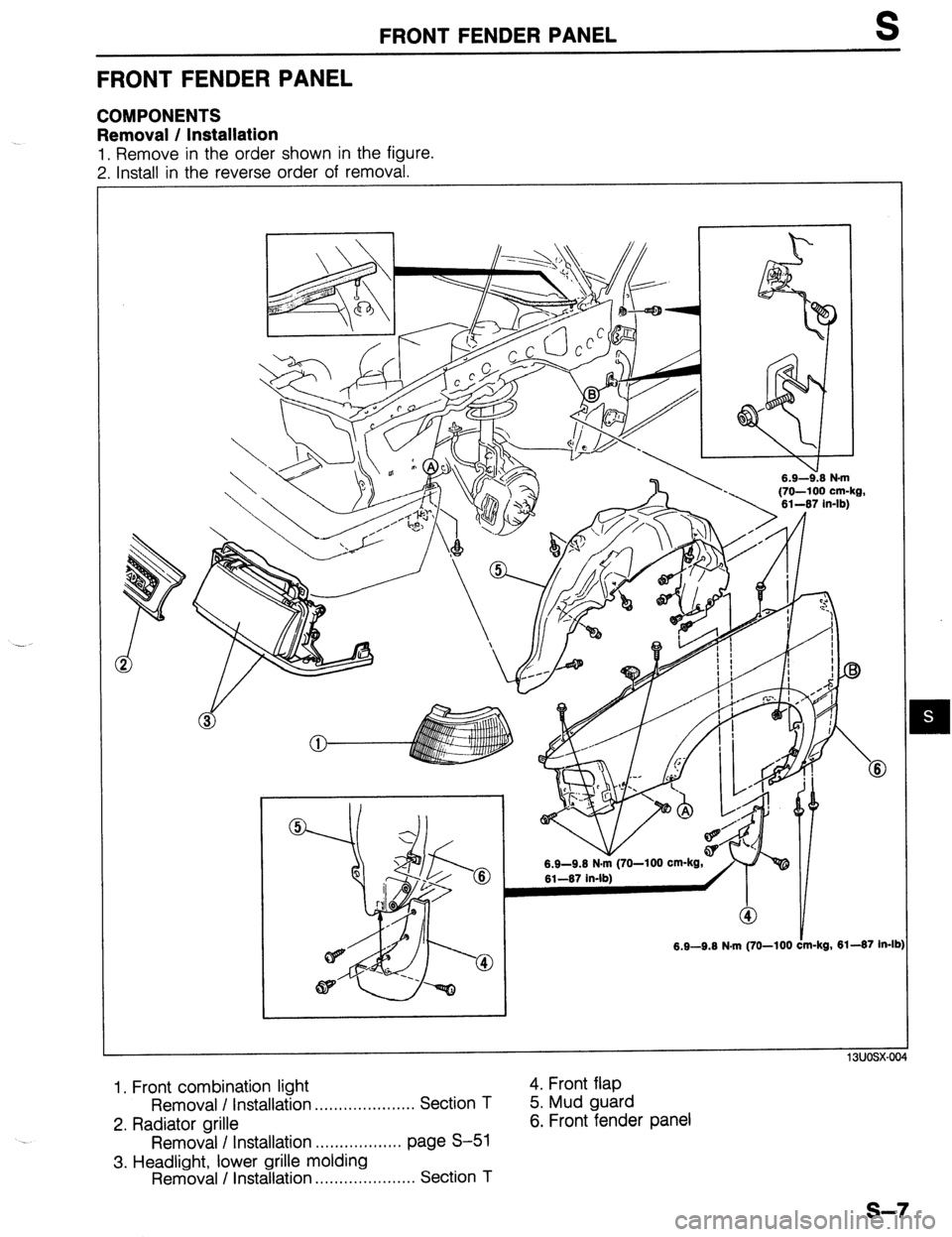
FRONT FENDER PANEL S
FRONT FENDER PANEL
COMPONENTS
Removal / Installation
1, Remove in the order shown in the figure.
7 Install in the reverse order of removal.
-. . . .-.-*. . .
6.9-9.6 N.m (70-100
13uosx-004
1. Front combination light
Removal I Installation . . . . . . . . . . . . . . . . . . . . . Section T
2. Radiator grille
Removal I Installation .,................ page S-51
3. Headlight, lower grille molding
Removal / Installation .,,.,......,......... Section T 4. Front flap
5. Mud guard
6. Front fender panel
s-7
Page 769 of 1164

TRUNK LID S
TRUNK LID
COMPONENTS
Removal / Installation
1. Disconnect the negative battery cable.
2. Remove in the order shown in the figure, referring to
Removal Note.
3. Install in the reverse order of removal, referrina to Installation Note.
m-kg, 69-95 in-lb)
1. Lid lock protector 6. High-mount stoplight (Interior mounted)
2. Trunk ooener cable Removal / Installation . . . . . . . . . . . . . . . . . . . . . Section T
3. Rear harness
4. Trunk lid
Adjustment Note . . . . . . . . . . . . . . . . . . . . . . . . . page S-34
5. Balance spring
Removal Note.. . . . . . . . . . . . . . . page S-34
Installation Note . .._. ._._.._.____...r..__ page S-34
Adjustment Note.. . . . . . . . . page S-34 7. Rear package trim
Removal / Installation . . . . . . . . . . . . . . . . . . page S-97
8. Lid hinge assembly
s-33
Page 775 of 1164

FRONT BUMPER S
FRONT BUMPER
COMPONENTS
Removal / Installation
1. Disconnect the negative battery cable.
2. Remove in the order shown in the figure.
3. Install in the reverse order of removal.
16-23 (1.6-2.3, 12-17
6.9-9.6 N.m (70-100 cc-kg,
61-67 in-lb) 16-23 (1.6-2.3, 12-17) /
6.9-9.6 N.m (70-100 cm-kg, 61-67 in-lb)
N.m (m-kg, Mb)
1. Front combination light
Removal / Installation . . . . . . . . . . . . . . . . . . . . . Section
T
2. Radiator grille
Removal I Installation . . . . . . . . . . . . . . . . . . page S-51
3. Headlight and lower grille molding
Removal / Installation . . . . . . . . . . . . . . . . . . . . . Section
T
4. Front bumper assembly
a. Front bumper reinforcement and bracket
b. Energy absorbing foam
c. Front bumper facia
5. License plate holder
6. Front bumper bracket
s-39