MAZDA PROTEGE 1992 Workshop Manual
Manufacturer: MAZDA, Model Year: 1992, Model line: PROTEGE, Model: MAZDA PROTEGE 1992Pages: 1164, PDF Size: 81.9 MB
Page 971 of 1164
TROUBLESHOOTING GUIDE U
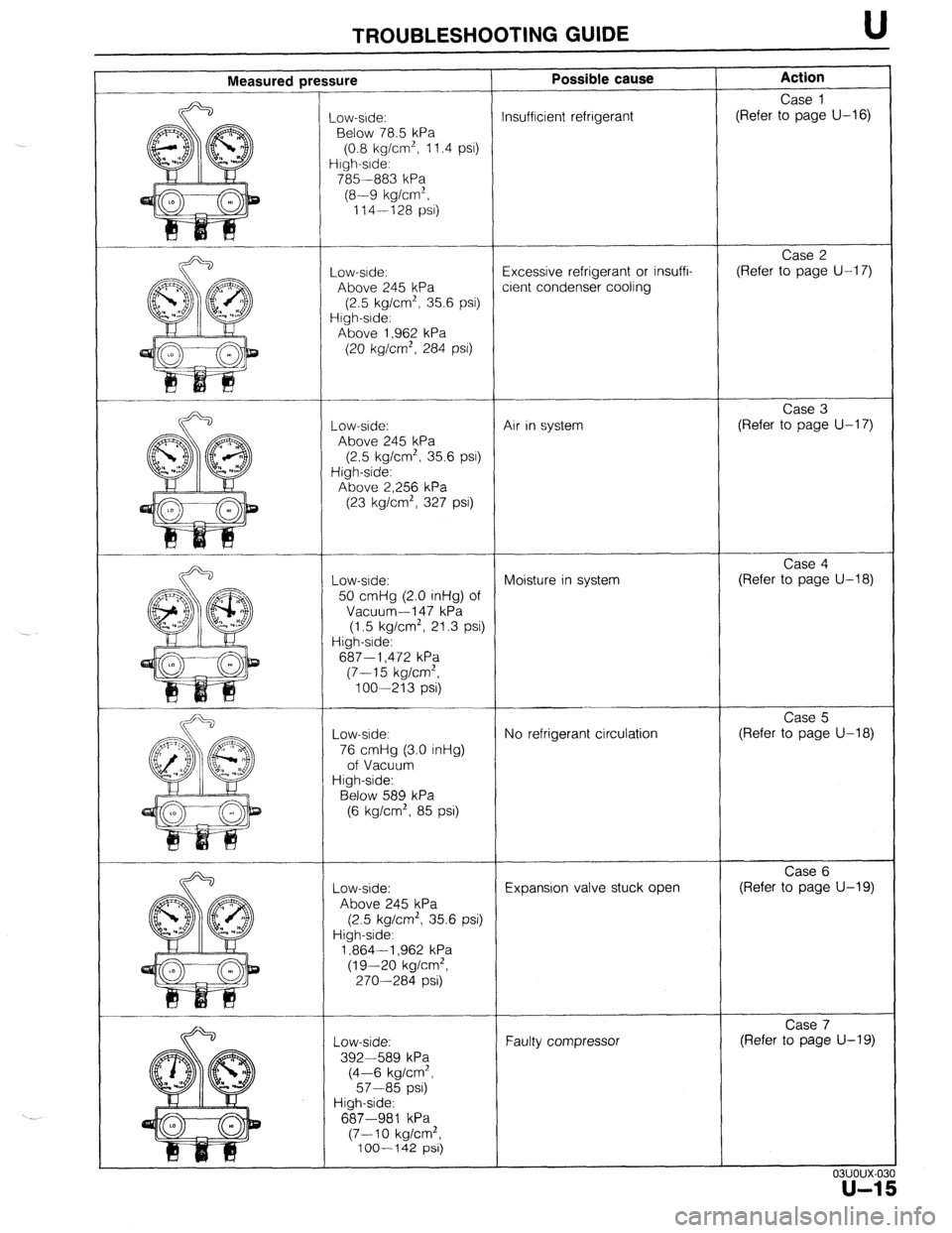
Measured press iure
_ow-side:
Below 78.5 kPa
(0.8 kg/cm’, 11.4 psi)
irgh-srde:
785 --883 kPa
(8-9 kg/cm’,
114-128 PSI)
-ow-srde:
Above 245 kPa
(2.5 kg/cm*, 35.6 psi)
iigh-srde:
Above 1,962 kPa
(20 kg/cm*, 284 PSI)
-ow-side:
Above 245 kPa
(2.5 kg/cm*, 35.6 PSI)
High-side:
Above 2,256 kPa
(23 kg/cm’, 327 psi)
Low-ade:
50 cmHg (2.0 inHg) of
Vacuum-l 47 kPa
(1.5 kg/cm2, 21.3 psi)
High-side:
687-i ,472 kPa
(7-15 kg/cm*,
loo-213 psi)
Low-side:
76 cmHg (3.0 inHg)
of Vacuum
High-side:
Below 589 kPa
(6 kg/cm’, 85 psi)
Low-side:
Above 245 kPa
(2.5 kg/cm’, 35.6 psi)
High-side:
1,864-l ,962 kPa
(19-20 kg/cm2,
270-284 psi)
-.
Low-side:
392-589 kPa
(4-6 kg/cm’,
57-85 psi)
High-side:
687-981 kPa
(7-10 kg/cm*,
100-I 42 psi)
T-
- Possible cause
nsufflcient refrigerant
!xcessive refrigerant or insuffi-
:ient condenser cooling
Air in system
Moisture in system
No refrigerant circulation
Expansion valve stuck open
Faulty compressor Action
Case 1
(Refer to page U-16)
Case 2
(Refer to page U-17)
Case 3
(Refer to page U-17)
Case 4
(Refer to page U-18)
Case 5
(Refer to page U-18)
Case 6
(Refer to page U-19)
Case 7
(Refer to page U-19)
03uoux-0:
u-1
Page 972 of 1164
U TROUBLESHOOTING GUIDE
Case 1: Insufficient refrigerant
Measured pressure
Low-pressure side: Less than 78.5 kPa (0.8 kg/cm2, 11.4 psi)
High-pressure side: 785-883 kPa (8-9 kg/cm2, 114-128 psi)
Condition
l Outlet air from vents not cold.
l Bubbles seen in sight glass.
Step 1
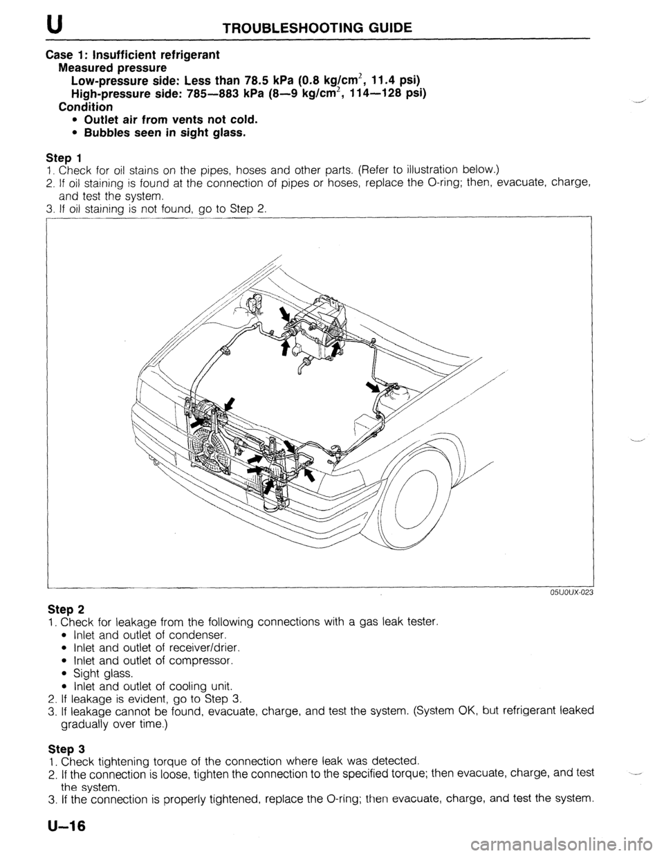
1. Check for oil stains on the pipes, hoses and other parts, (Refer to illustration below.)
2. If oil staining is found at the connection of pipes or hoses, replace the O-ring; then, evacuate, charge,
and test the system.
3. If oil staining is not found, go to Step 2.
05UOUX-02
Step 2
1. Check for leakage from the following connections with a gas leak tester.
l Inlet and outlet of condenser.
l Inlet and outlet of receiver/drier.
l Inlet and outlet of compressor.
l Sight glass.
l Inlet and outlet of cooling unit.
2. If leakage is evident, go to Step 3.
3. If leakage cannot be found, evacuate, charge, and test the system. (System OK, but refrigerant leaked
gradually over time.)
Step 3
1. Check tightening torque of the connection where leak was detected.
2. If the connection is loose, tighten the connection to the specified torque; then evacuate, charge, and test
the system. --
3. If the connection is properly tightened, replace the O-ring; then evacuate, charge, and test the system.
U-16
Page 973 of 1164
TROUBLESHOOTING GUIDE U
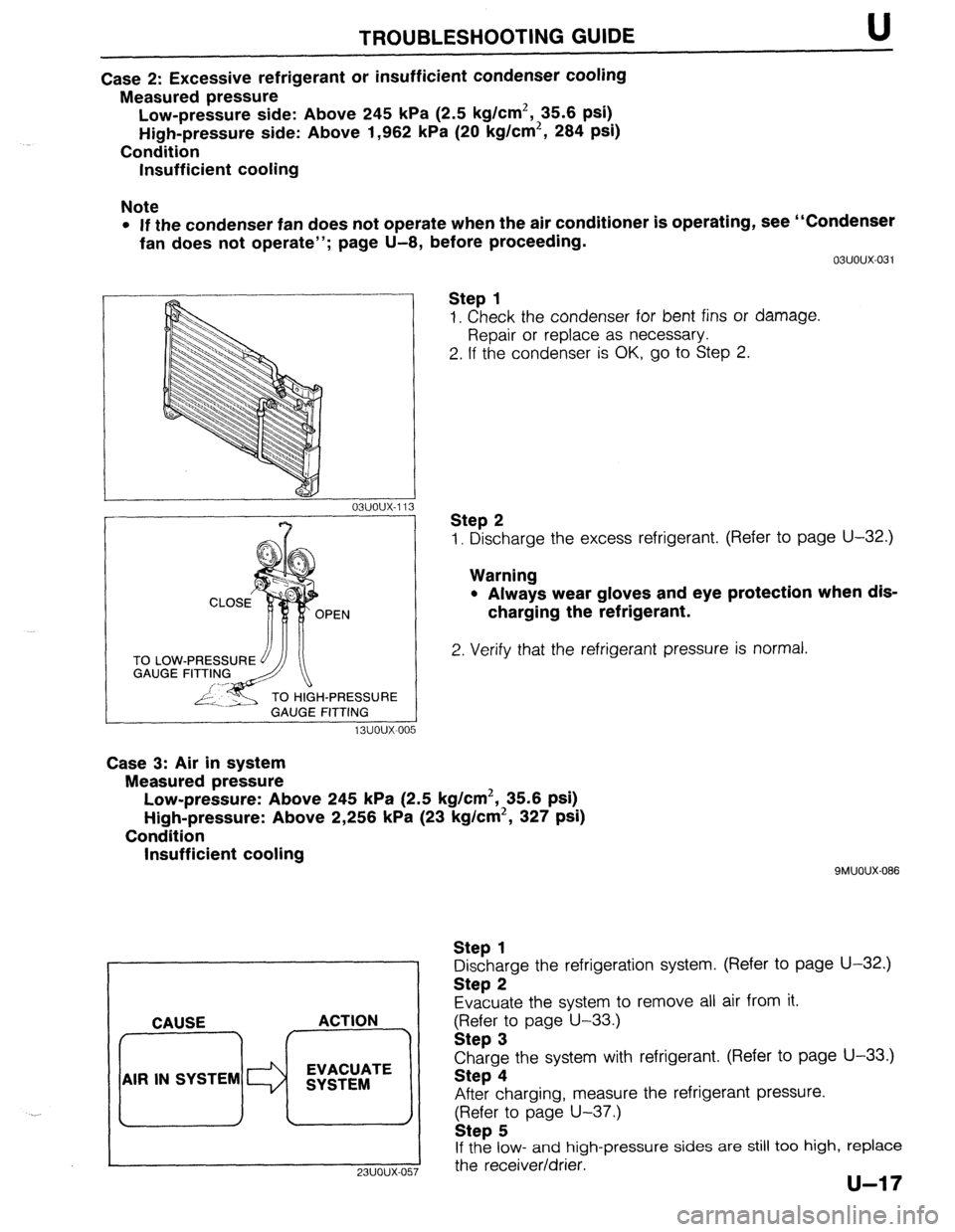
Case 2: Excessive refrigerant or insufficient condenser cooling
Measured pressure
Low-pressure side: Above 245 kPa (2.5 kg/cm2, 35.6 psi)
High-pressure side: Above 1,962 kPa (20 kg/cm2, 284 psi)
Condition
Insufficient cooling
Note
l If the condenser fan does not operate when the air conditioner is operating, see “Condenser
fan does not operate”; page U-8, before proceeding.
TO LOW
GAUGE
H-PRESSURE
GAUGE FITTING
13uoux-00 5 03uoux-031
Step 1
1. Check the condenser for bent fins or damage.
Repair or replace as necessary.
2. If the condenser is OK, go to Step 2.
Step 2
1. Discharge the excess refrigerant. (Refer to page U-32.)
Warning
l Always wear gloves and eye protection when dis-
charging the refrigerant.
2. Verify that the refrigerant pressure is normal.
Case 3: Air in system
Measured pressure
Low-pressure: Above 245 kPa (2.5 kg/cm2, 35.6 psi)
High-pressure: Above 2,256 kPa (23 kg/cm2, 327 psi)
Condition
Insufficient cooling
. . CAUSE ACTION
AIR IN SYSTEM EVACUATE
SYSTEM
9MUOUX-086
Step 1
Discharge the refrigeration system. (Refer to page U-32.)
Step 2
Evacuate the system to remove all air from it.
gFI;;r; page U-33.)
Charge the system with refrigerant. (Refer to page U-33.)
Step 4
After charging, measure the refrigerant pressure.
(Refer to page U-37.)
Step 5
If the low- and high-pressure sides are still too high, replace
I
23UOUX-057 the receiver/drier.
Page 974 of 1164
U TROU6LESHOOTlNG GUIDE
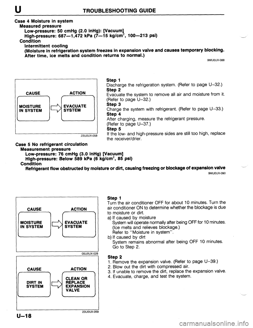
Case 4 Moisture in system
Measured pressure
Low-pressure: 50 cmHg (2.0 inHg): [Vacuum1
High-pressure: 667-l ,472 kPa (7-15 kg/cm , loo-213 psi)
Condition
Intermittent cooling
(Moisture in refrigeration system freezes in expansion valve and causes temporary blocking.
After time, ice melts and condition returns to normal.)
SMUOUX-088
CAUSE ACTION
7 r
MOISTURE
IN SYSTEM WW;MTE
-
23uoux-O!
Case 5 No refrigerant circulation
Measurement pressure
Low-pressure: 76 cmHg (3.0 inHg) [Vacuum]
High-pressure: Below 589 kPa (6 kg/cm’, 85 psi)
Condition
Refrigerant flow obstructed by moisture or dirt, causing freezing or blockage of expansion valve
9MUOUX.090
Step 1
Discharge the refrigeration system, (Refer to page U-32.)
Step 2
Evacuate the system to remove all air and moisture from it.
$?&$r:o page U-32.)
Charge the system with refrigerant. (Refer to page U-33.)
Step 4
After charging, measure the refrigerant pressure.
(Refer to page U-37.)
Step 5
If the low- and high-pressure sides are still too high, replace
the receiver/drier.
CAUSE ACTION
f r^‘---7
MOISTURE
Id EVACUATE
IN SYSTEM SYSTEM
I I
05UOUX-02
CAUSE ACTION
23UOUX-OE
Step 1
Turn the air conditioner OFF for about 10 minutes. Turn the
air conditioner ON to determine whether the blockage is due
to moisture or dirt.
a) If caused by moisture
System will operate normally after being OFF for 10 minutes.
(Ice melts and relieves blockage.)
Refer to “Moisture in system”.
b) If caused by dirt
System remains abnormal after being OFF 10 minutes.
Go to Step 2.
Step 2
1. Remove the expansion valve. (Refer to page U-39.)
2. Blow out the dirt with compressed air.
3. If unable to remove the dirt, replace the expansion valve.
4. Evacuate, charge, and test the system.
U-18
Page 975 of 1164
TROUBLESHOOTING GUIDE U
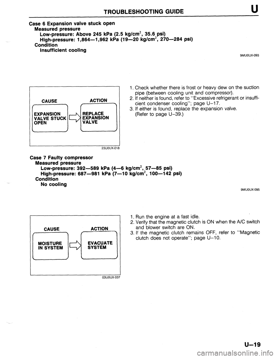
Case 6 Expansion valve stuck open
Measured pressure
Low-pressure: Above 245 kPa (2.5 kg/cm2, 35.6 psi)
High-pressure: 1,864-l ,962 kPa (19-20 kg/cm2, 270-284 psi)
Condition
Insufficient cooling
QMUOUX-093
23UOUX-01’
1. Check whether there is frost or heavy dew on the suction
pipe (between cooling unit and compressor).
2. If neither is found, refer to “Excessive refrigerant or insuffi-
cient condenser cooling”; page U-17.
3. If either is found, replace the expansion valve.
(Refer to page U-39.)
Case 7 Faulty compressor
Measured pressure
Low-pressure: 392-589 kPa (4-6 kg/cm2, 57-85 psi)
High-pressure: 687-981 kPa (7-10 kg/cm2, loo-142 psi)
Condition
No cooling
MOISTURE EVACUATE
IN SYSTEM SYSTEM
I
9MUOUX-095
1. Run the engine at a fast idle.
2. Verify that the magnetic clutch is ON when the A/C switch
and blower switch are ON.
3. If the magnetic clutch remains OFF, refer to “Magnetic
clutch does not operate”; page U-10.
u-19
Page 976 of 1164
U HEATER
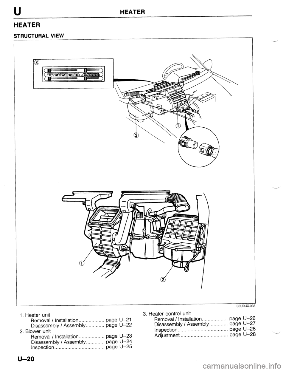
HEATER
STRUCTURAL VIEW
1, Heater unit 3. Heater control unit
Removal / Installation.. page U-21 Removal / Installation.. ................ page U-26
................
Disassembly I Assembly.. ........... page U-22 Disassembly I Assembly.. ........... page U-27
2. Blower unit inspection ................................... page U-28
Removal I Installation.. page U-23 Adjustment ................................. page U-28
................
Disassembly / Assembly ............. page U-24
Inspection
................................... page U-25
u-20
Page 977 of 1164
HEATER U
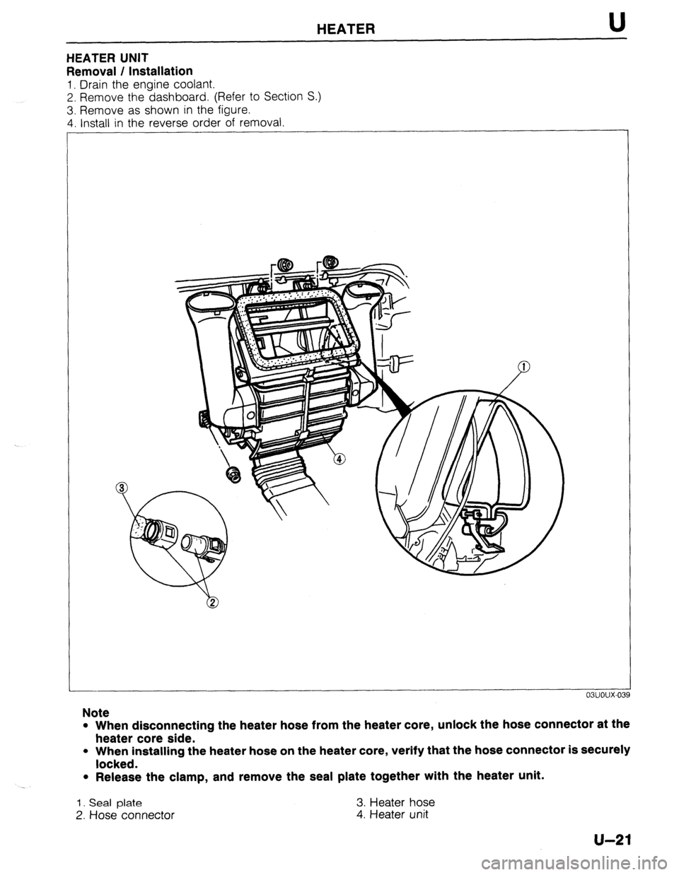
HEATER UNIT
Removal / Installation
1. Drain the engine coolant.
2. Remove the dashboard. (Refer to Section S.)
3. Remove as shown in the figure.
4. Install in the reverse order of removal
Note
l When disconnecting the heater hose from the heater core, unlock the hose connector at the
heater core side.
l When installing the heater hose on the heater core, verify that the hose connector is securely
locked.
l Release the clamp, and remove the seal plate together with the heater unit.
1. Seal plate 3. Heater hose
2. Hose connector
4. Heater unit
u-21
Page 978 of 1164
U HEATER
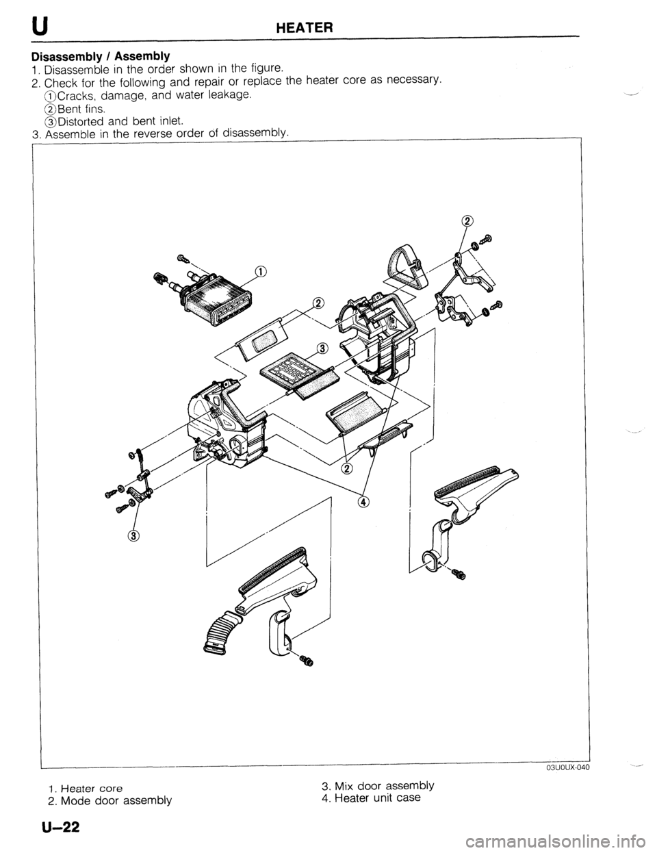
Disassembly / Assembly
1. Disassemble in the order shown in the figure.
2. Check for the following and repair or replace the heater core as necessary.
@Cracks, damage, and water leakage.
@Bent fins.
@Distorted and bent inlet.
3. Assemble in the reverse order of disassembly.
1
-
1. Heater core 3. Mix door assembly
2. Mode door assembly 4. Heater unit case
u-22
Page 979 of 1164
HEATER U
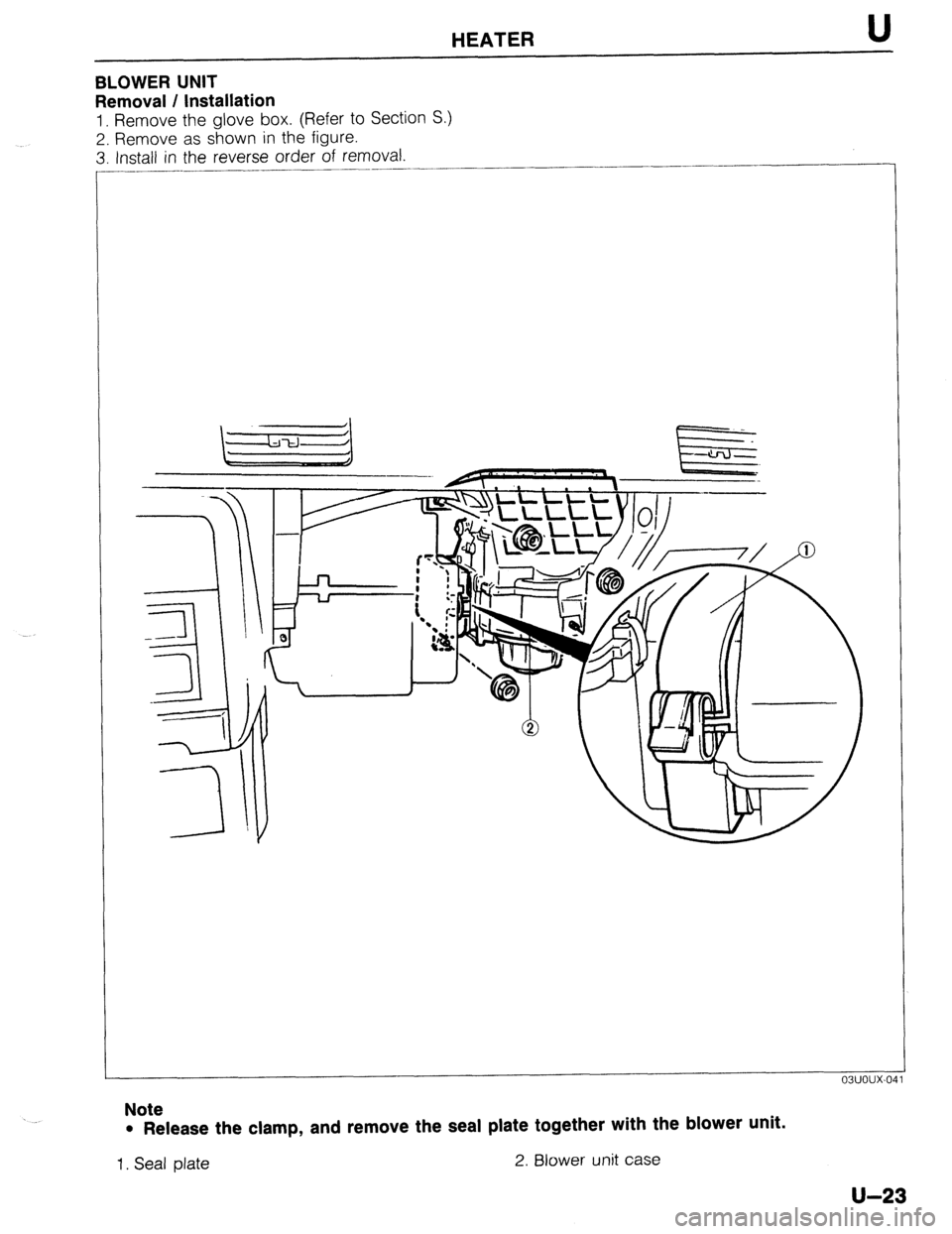
BLOWER UNIT
Removal / Installation
1. Remove the glove box. (Refer to Section S.)
2. Remove as shown in the figure.
3. Install in the reverse order of removal.
____..
Note
l Release the clamp, and remove the seal plate together with the blower unit.
1. Seal plate 2. Blower unit case
U-23
Page 980 of 1164
U HEATER
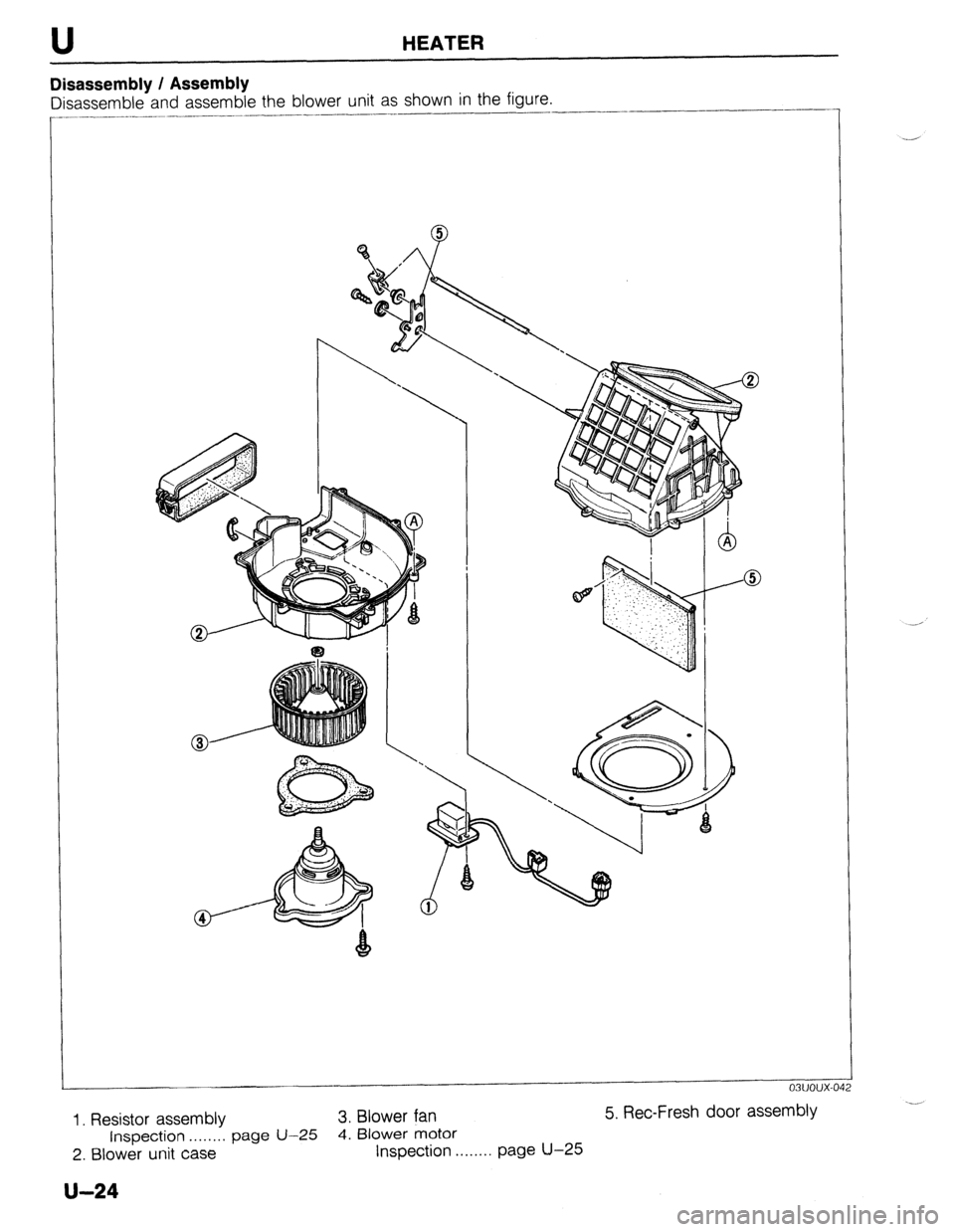
Disassembly / Assembly
Disassemble and assemble the blower unit as shown in the figure.
I
f-4
@X1; ;:‘::j: :‘.;.; .,,,
:. ..
Q . ...;,
: ., ‘,:
-,: ,..’
, :
03uoux-01
1. Resistor assembly 3. Blower fan 5. Ret-Fresh door assembly
Inspection . . . . . . . . page U-25
4. Blower motor
2. Blower unit case Inspection . . . . . . . . page U-25
U-24