MERCEDES-BENZ C-Class SEDAN 2013 W204 Owner's Manual
Manufacturer: MERCEDES-BENZ, Model Year: 2013, Model line: C-Class SEDAN, Model: MERCEDES-BENZ C-Class SEDAN 2013 W204Pages: 358, PDF Size: 4.85 MB
Page 261 of 358

Observe the loading guidelines (Y
page 256).
The left-hand and right-hand rear seat
backrests can be folded down separately to
increase the trunk capacity.
Folding the seat backrest forward X
Move the driver's or front-passenger seat
forward if necessary.
X Open the trunk.
X Pull right-hand or left-hand rear seat
backrest release handle 0002.
The corresponding rear seat backrest is
released.
X Fully insert the rear seat backrest head
restraints. X
Fold rear seat backrest 0003forwards.
X Move the driver's or front-passenger seat
back if necessary. Folding the seat backrest back
X
Move the driver's or front-passenger seat
forward if necessary.
! Make sure that the seat belt does not
become trapped when folding the rear seat
backrest back. Otherwise, it could be
damaged.
X Fold rear seat backrest 0002back until it
engages.
If the rear seat backrest is not engaged and
locked, this will be shown in the
multifunction display in the instrument
cluster. Awarning tone also sounds.
i You should always engage the rear seat
backrests if you do no tneed the through-
loading feature. This will prevent
unauthorized access to the trunk from the
vehicle interior.
X Adjust the head restraints if necessary
(Y page 98).
X Move the driver's or front-passenger seat
back if necessary. Securing cargo
Cargo tie-down rings Observe the following notes on securing
loads:
R
Observe the loading guidelines
(Y page 256).
R Secure the load using the cargo tie-down
rings. Stowage areas
259Stowage and features Z
Page 262 of 358

R
Distribute the load on the cargo tie down
rings evenly.
R Do not use elastic straps or nets to secure
a load, as these are only intended as an
anti-slip protection for ligh tloads.
R Do not route tie-downs across sharp edges
or corners.
R Pad sharp edges for protection.
There are four cargo tie down rings in the
trunk. Vehicle with through-loading feature in the rear
bench seat
0002 Cargo tie-down rings
Bag hook G
WARNING
The bag hooks cannot restrain heavy objects
or items of luggage. Objects or items of
luggage could be flung around and thereby hit
vehicle occupants when braking or abruptly
changing directions. There is a risk of injury.
Only hang light objects on the bag hooks.
Never hang hard, sharp-edged or fragile
objects on the bag hooks.
! The bag hook can bear a maximum load
of 11lbs (5kg) and should not be used to
secure a load. 0002
Bag hook Stowage well under the trunk floor
The TIREFIT kit, the vehicle tool kit, etc. are
located in the stowage compartment. X
To open: pull handle 0002up. X
Hook handle 0002into rain trough 0003.
! Unhook the handle before again before
closing the trunk lid and clip it in securely
to prevent the handle flap from protruding.
Otherwise, you could damage the handle. 260
Stowage areasStowage and features
Page 263 of 358

Roof carrier
Important safety notes G
WARNING
Whe nyou load the roof, the center of gravity
of the vehicle rises and the driving
characteristics change. If you exceed the
maximum roof load, the driving
characteristics, as well as steering and
braking, will be greatly impaired. There is a
risk of an accident.
Never exceed the maximum roof load and
adjust your driving style.
! Mercedes-Benz recommends that you
only use roof carriers that have been tested
and approved for Mercedes-Benz vehicles.
This helps to prevent damage to the
vehicle.
Position the load on the roof carrier in such
a way that the vehicle will not sustain
damage even when it is in motion.
Depending on the vehicle equipment,
ensure that when the roof carrier is
installed you can:
R raise the sliding sunroof fully
R open the panorama roof with power tilt/
sliding panel fully
R open the trunk lid fully
! To avoid damaging or scratching the
covers, do not use metallic or hard objects
to open them.
The maximum roof load is 220 lbs(100 kg).
An incorrectly secured roof carrier or roof
load could become detached from the
vehicle. Therefore, always comply with the
installation instructions supplied by the
manufacturer of the roof carrier. Attaching the roof carrier X
Open covers 0002carefully in the direction of
the arrow.
X Fold covers 0002upwards.
X Only secure the roof carrier to the
anchorage points under covers 0002.
X Observe the manufacturer' sinstallation
instructions. Features
Cup holder
Important safety notes !
Only use the cup holders for containers of
the right size and which have lids. The
drinks could otherwise spill.
Cup holder in the front-compartment
cente rconsole 0002
Cup holder Features
261Stowage and features Z
Page 264 of 358

Cup holder in the rear seat armrest
!
Do no tsit on or support your body weight
on the rear seat armrest when it is folded
down, as you could otherwise damage it.
! Close the cup holder before folding the
rear seat armrest up. Otherwise, the cup
holder could be damaged. X
Fold down the rear seat armrest.
X To open: raise the rear seat armrest cover.
X Press release catch 0002.
Cup holder 0003folds out forwards.
X Swing the rear seat armrest cover back
down, if necessary.
X To close: raise the rear seat armrest cover.
Swing cup holder 0003back until it engages. Sun visors
Overview G
WARNING
If the mirror cover of the vanity mirror is folded
up when the vehicle is in motion, you could be
blinded by incident light .There is a risk of an
accident.
Always keep the mirror cover folded down
while driving. 0002
Mirror light
0003 Bracket
0022 Retaining clip, e.g. for a car park ticket
0021 Vanity mirror
001F Mirror cover
Vanity mirror in the sun visor Mirror light
0002only functions if the sun visor
is clipped into bracket 0003and mirror cover
001F has been folded up.
Glare from the side X
Fold down the sun visor.
X Pull the sun visor out of retainer 0003.
X Swing the sun visor to the side. X
Pull or push the sun visor in the direction of
the arrow. 262
FeaturesStowage and features
Page 265 of 358

Rolle
rsunblinds on the rear side
windows
! Always guide the roller sunblind by hand.
Do not let it snap back suddenly as this
would damage the automatic roller
mechanism.
! Do not drive the vehicle with the roller
sunblind hooked in and the side windows
opened simultaneously. The roller sunblind
can jump out of the retainers and spring
back suddenly whe ndriving at high speeds,
e.g. when driving on the freeway.T his could
damage the inertia reel. Therefore, either
close the side window or retract the roller
sunblind before driving at high speeds. X
To extend: pull the roller sunblind out by
tab 0002and hook it onto retainers 0003at the
top of the window. Rear window roller sunblind (Sedan)
Important safety notes G
WARNING
When extending or retracting, parts of the
body could become trapped within the sweep
of the roller sunblind. There is a risk of injury.
When extending or retracting, make sure that
no one has any parts of the body within the
sweep of the roller sunblind. If someone
becomes trapped, briefly press the button
again. The opening or closing procedure will
be stopped. !
Make sure that the roller sunblind can
move freely. Otherwise, the roller sunblind
or other objects could be damaged.
Extending/retracting the roller
sunblind X
Turn the SmartKey to position 2in the
ignition lock (Y page 141).
X To extend or retract: briefly press
button 0002.
The roller sunblind fully extends or fully
retracts.
X To stop: briefly press button 0002again.
The roller sunblind stops briefly and moves
back into the out-of-use position. Ashtray
Front ashtray !
The stowage space under the ashtray is
not heat resistant. Before placing lit
cigarettes in the ashtray, make sure that
the ashtray is properly engaged. Otherwise,
the stowage space could be damaged.
i You can remove the ashtray insert and
use the resulting compartmentf or
stowage. Features
263Stowage and features Z
Page 266 of 358

X
To open: slide cover 0002forwards until it
engages.
X To remove the insert: hold insert0022by
the ribbing at the sides and lift it up 0003and
out.
X To re-install the insert: press insert0022
into the holde runtil it engages.
X To close: briefly press cover 0002at the
front.
The cove rmoves back.
Rear-compartment ashtray X
To open: pull cover 0003out by its top edge.
X To remove the insert: press release
button 0022and lift the insert up and out.
X To install the insert: install insert0002from
above into the holder and press down into
the holder until it engages. Cigarette lighter
G
WARNING
You can burn yourself if you touch the hot
heating element or the socket of the cigarette
lighter.
In addition, flammable materials can ignite if:
R the hot cigarette lighter falls
R a child holds the hot cigarette lighter to
objects, for example
There is a risk of fire and injury.
Always hold the cigarette lighter by the knob.
Always make sure that the cigarette lighter is
out of reach of children. Never leave children
unsupervised in the vehicle.
Your attention must always be focused on the
traffic conditions. Only use the cigarette
lighter when road and traffic conditions
permit. X
Turn the SmartKey to position 2in the
ignition lock (Y page 141).
X To open: slide cover 0002forwards until it
engages.
X Press in cigarette lighter 0003.
Cigarette lighter 0003will pop out
automatically when the heating element is
red-hot.
X To close: briefly press cover 0002at the
front.
The cover moves back. 264
FeaturesStowage and features
Page 267 of 358

12
Vsockets
General notes The sockets can be used for accessories with
a maximum draw of 180 W (15 A).
Accessories include such items as lamps or
chargers for mobile phones.
If you use the sockets for long periods when
the engine is switched off ,the battery may
discharge.
X Turn the SmartKey to position 1in the
ignition lock (Y page 141).
i An emergency cut-out ensures that the
on-board voltage does not drop too low. If
the on-board voltage is too low, the power
to the sockets is automatically cut. This
ensures that there is sufficient power to
start the engine.
Socket in the rear-compartment center
console X
Pull cover 0003out by its top edge.
X Lift up the cover of socket 0002.115
Vsocket
Important safety notes G
DANGER
When a suitable device is connected, the
11 5Vp ower socket will be carrying a high
voltage. You could receive an electric shock
if the connector cable or the 115 V power socket is pulled out of the trim or is damaged
or wet. There is a risk of fatal injury.
R
Use only connector cables that are dry and
free of damage.
R When the ignition is off, make sure that the
115 V power socket is dry.
R Have the 115 V power socket checked or
replaced immediately at a qualified
specialized workshop if it is damaged or has
been pulled out of the trim.
R Never plug the connector cable into a
115 Vpower socket that is damaged or has
been pulled out of the trim. G
DANGER
If you reach into the power socket or plug
inappropriate devices into the power socket,
you could receive an electric shock. There is
a risk of fatal injury.
Only connect appropriate devices to the
power socket.
! Note that work and repairs on the 115 V
power socket should only be carried out by
qualified specialist personnel.
General notes 115 V power socket
0002provides an
alternating voltage of 115 V so that small
electronic devices can be connected. These
devices, such as games consoles, chargers
and laptops, should not consume more than
a maximum of 150 watts altogether.
Requirements for operation of these devices:
R the electronic device that you connect has
a suitable connector and conforms to
standards specific to the country you are
in.
R the plug of the electronic device is plugged
into 115 V power socket 0002.
R the maximum wattage of the device to be
connected must not exceed 150 watts. Features
265Stowage and features Z
Page 268 of 358

R
the on-board powe rsupply is within a
permissible voltage range.
R the 12 V sockets in the rear compartment
are operational (Y page 265).
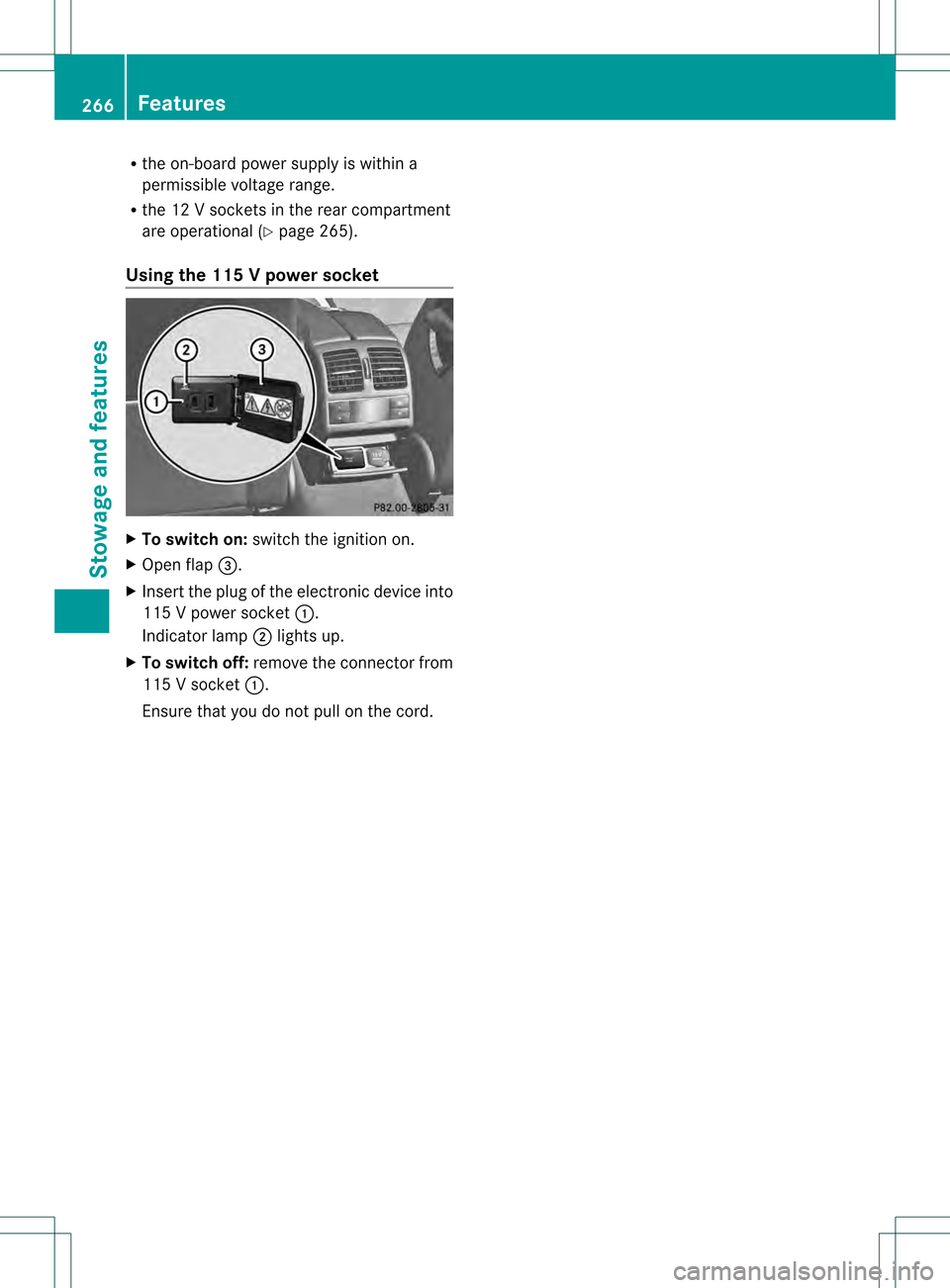
Using the 115 Vpower socket X
To switch on: switch the ignitio non.
X Ope nflap 0022.
X Insert the plug of the electronic device into
115 V power socket 0002.
Indicator lamp 0003lights up.
X To switch off: remove the connector from
115 V socket 0002.
Ensure that you do not pull on the cord. 266
FeaturesStowage and features
Page 269 of 358

Problems with the 115
Vpower socket Problem Possible causes/consequences and
0001 Solutions
The warning lamp on
the 11
5Vpower socket
is not lit. The on-board voltage is too low because the battery is too weak.
X
Start the engine.
or
X Charge the battery (Y page 300).
If the indicator lamp still does not light up:
X Visit a qualified specialist workshop. The temperature of the DC/AC converter is temporarily too high.
X Remove the electronic device connector from the 115 V socket.
X Let the DC/AC converter cool down.
If the indicator lamp still does not light up after cooling down the
converter:
X Visit a qualified specialist workshop. You have connected a small electronic device that has a constant
nominal power of less than 150 W, but a very high switch-on
current. This device will not work. If you connect such a device,
the 115
Vpower socket will not supply it with power.
X Connect a suitable device. mbrace
Important safety notes !
You must have a license agreement to
activate the mbrace service. Make sure
that your system is activated and ready for
use. To register, press the 0009MB Info call
button. If any of the steps mentioned are
not carried out, the system may not be
activated.
If you have questions about the activation,
contact one of the following telephone
hotlines:
R USA: Mercedes-Benz Customer
Assistance Center at
1-800-FOR-MERCedes
(1-800-367-6372) or 1-866-990-9007
R Canada: Customer Service at
1-888-923-8367 Shortly after successfully registering with the
mbrace service (Canada: TELEAID), a user ID
and password will be sent to you by post. USA
only: you can use this password to log onto
the mbrace area under "Owners Online" at
http://www.mbusa.com.
The mbrace system is available if:
R
it has been activated and is operational
R the corresponding mobile phone network
is available for transmitting data to the
Customer Center
R a service subscription is available
R the starter battery is sufficiently charged
i Determining the location of the vehicle on
a map is only possible if:
R GPS reception is available.
R the vehicle position can be forwarded to
the Customer Assistance Center. Features
267Stowage and features Z
Page 270 of 358

The mbrace system
To adjus
tthe volume during an mbrace call,
proceed as follows:
X Press the 0009or000A button on the
multifunction steering wheel.
or
X Use the volume controller of the audio
system/COMAND.
The mbrace system provides various
services, e.g.:
R automatic and manual emergency call
R Roadside Assistance call
R MB Info call
USA only: you can find information and a
description of all available features under
"Owners Online" at http://www.mbusa.com.
System self-test After you have switched on the ignition, the
system carries out a self-diagnosis.
Am
alfunction in the system has been
detected if one of the following occurs:
R The indicator lamp in the SO Sbutton does
not come on during the system self-test.
R The indicator lamp in the 0007Roadside
Assistance butto ndoes not light up during
self-diagnosis of the system.
R The indicator lamp in the 0009MB Info call
button does not light up during self-
diagnosis of the system.
R The indicator lamp in one or more of the
following buttons continues to light up red
after the system self-diagnosis:
- SOS button
- the 0007 Roadside Assistance call
button
- the 0009 MB Info call button
R The mbrace Inoperative or
mbrace Service Not Activated message
appears in the multifunction display after
the system self-diagnosis. If a malfunction is indicated as outlined
above, the system may not operate as
expected. In the event of an emergency, help
will have to be summoned by other means.
Have the system checked at the nearest
authorized Mercedes-Benz Center or contact
the following service hotlines:
R
USA: Mercedes-Benz Customer Assistance
Center at
1-800-FOR-MERCedes (1-800-367-6372)
or 1-866-990-9007
R Canada: Customer Service at
1-888-923-8367
Emergency call Important safety notes
!
You must have a license agreement to
activate the mbrace service. Make sure
that your system is activated and ready for
use. To register, press the 0009MB Info call
button. If any of the steps mentioned are
not carried out, the system may not be
activated.
If you have questions about the activation,
contact one of the following telephone
hotlines:
R USA: Mercedes-Benz Customer
Assistance Center at
1-800-FOR-MERCedes
(1-800-367-6372) or 1-866-990-9007
R Canada: Customer Service at
1-888-923-8367
General notes
An emergency call is dialed automatically if
an air bag or Emergency Tensioning Device is
triggered.
i You cannot end an automatically
triggered emergency call yourself.
An emergency call can also be initiated
manually.
As soon as the emergenc ycall has been
initiated, the indicator lamp in the SO Sbutton 268
FeaturesStowage and featu
res