MERCEDES-BENZ E-CLASS ESTATE 2016 Owners Manual
Manufacturer: MERCEDES-BENZ, Model Year: 2016, Model line: E-CLASS ESTATE, Model: MERCEDES-BENZ E-CLASS ESTATE 2016Pages: 565, PDF Size: 11.34 MB
Page 141 of 565
Setting
the sur round lighting Re
quirement:
The light switch is in theà position.
Multimedia sy stem:
, Vehicle .
÷ Light settings .
Loca-
tor lighting
Exterior switch-off delay time: theex terior
lighting is switched on for a short time af terthe
ve hicle is switched off. #
Set the switch-off delay time.
Locator lighting: if a switch-off delay time is
set, theex terior lighting remains lit for 30 sec‐
onds af terth eve hicle is unloc ked. When you
st art theve hicle, the locator lighting is switched
off and automatic driving lights are activated. Interior lighting
Ad
justing the in terior lighting Fr
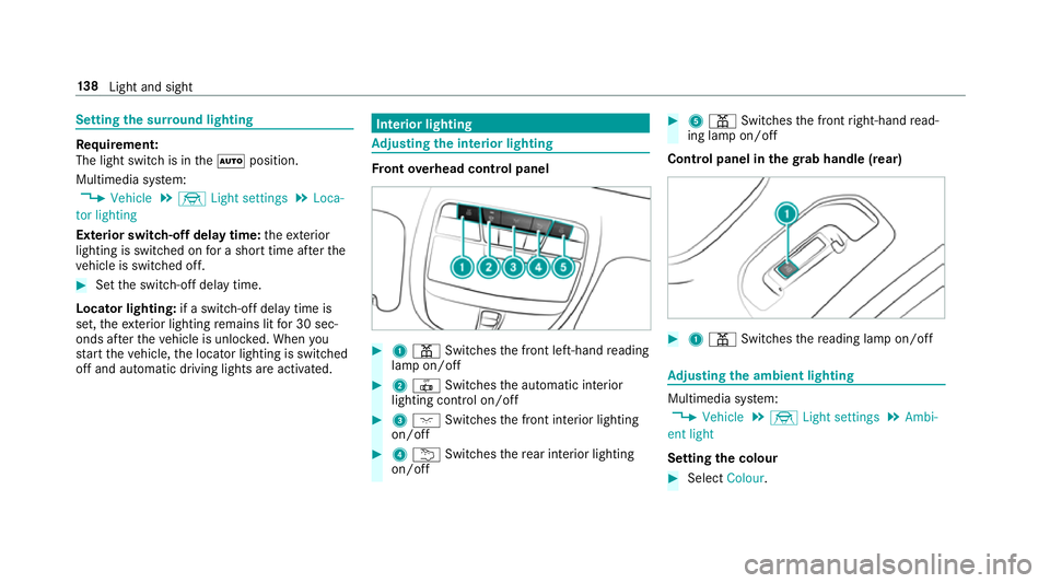
ont overhead control panel #
1 p Switches the front left-hand reading
lamp on/off #
2 | Switches the automatic interior
lighting control on/off #
3 c Switches the front interior lighting
on/off #
4 u Switches there ar interior lighting
on/off #
5 p Switches the front right-hand read‐
ing lamp on/off
Cont rol panel in thegr ab handle (rear) #
1 p Switches there ading lamp on/off Ad
justing the ambient lighting Multimedia sy
stem:
, Vehicle .
÷ Light settings .
Ambi-
ent light
Setting the colour #
Select Colour. 13 8
Light and sight
Page 142 of 565
#
Set the colour.
Setting the brightness for zones #
Select Entire vehicle ,Front ,Rear orDisplay. #
Set the brightness value. Setting
the interior lighting switch-off delay
time Multimedia sy
stem:
, Vehicle .
÷ Light settings .
Int.
light delay shut-off #
Set the switch-off delay time. Changing bulbs (only
forve hicles with halo‐
ge n headla mps) Note
s onchanging bulbs &
WARNING Risk of bu rns from hot com‐
ponent parts whilst replacing a bulb
Bulbs, lamps and plug connec tors can
become very hot during operation. When
replacing a bulb, you could burn your‐
self on these component parts. #
Allow the component parts tocool
down before replacing the bulbs. R
Do not use a bulb if it has been dropped or if
itsglass tube has been sc ratched. The bulb
may otherwise explode.
R Do not touch theglass tube with your bare
hands.
R Protect bulbs from moisture and do not allow
bulbs tocome into contact wi thliquids. Overview of light source types
The
following bulbs can be replaced. Halogen headlamps
1 Turn signal light: PY 21 W
2 Main beam: H7 55 W
3 Dipped beam: H7 55 W Light and sight
13 9
Page 143 of 565
Changing
the front bulbs (vehicles with halo‐
ge n headla mps) Fi
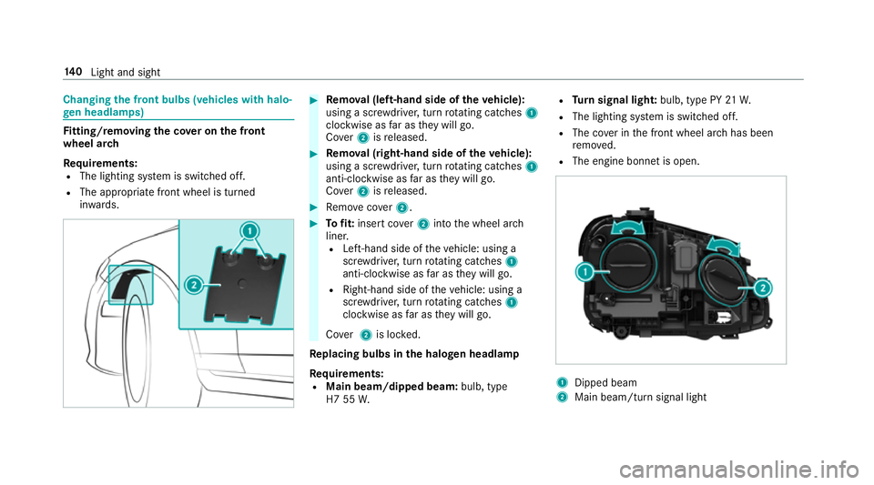
tting/ removing the co ver on the front
wheel ar ch
Re quirements:
R The lighting sy stem is switched off.
R The appropriate front wheel is turned
in wa rds. #
Remo val (left-hand side of theve hicle):
using a scr ewdriver, turn rotating catches 1
clo ckwise as far as they will go.
Co ver2 isreleased. #
Remo val (right-hand side of theve hicle):
using a scr ewdriver, turn rotating catches 1
anti-clo ckwise as far as they will go.
Co ver2 isreleased. #
Remo vecover2. #
Tofit: inse rtco ver2 into the wheel ar ch
liner.
R Left-hand side of theve hicle: using a
scr ewdriver, turn rotating catches 1
anti-clo ckwise as far as they will go.
R Right-hand side of theve hicle: using a
scr ewdriver, turn rotating catches 1
clo ckwise as far as they will go.
Co ver2 is loc ked.
Re placing bulbs in the halo gen headla mp
Requ irements:
R Main beam/dipped beam: bulb, type
H7 55 W. R
Turn signal light: bulb, type PY 21W.
R The lighting sy stem is switched off.
R The co ver in the front wheel ar chhas been
re mo ved.
R The engine bonn etis open. 1
Dipped beam
2 Main beam/turn signal light 14 0
Light and sight
Page 144 of 565
#
Turn there leva nt housing co ver anti-clock‐
wise and remo veit. #
Main beam/dipped beam: turnthe soc ket
anti-clockwise and remo veit. #
Turn signal light: turnthe soc ket anti-clo ck‐
wise, unlock and remo veit. #
Pull the bulb out of the soc ket. #
Inse rtthe new bulb into the soc ket so that
th e entire base of the bulb is resting on the
bottom of the soc ket. #
Inse rtsoc ket and turn it clo ckwise. #
Press on the housing co ver and turn it clock‐
wise. #
Replace the co ver in the front wheel ar ch. Wi
ndscreen wipers and windscreen washer
sy stem Switching
the windscreen wipers on/off #
1 í Single wipe/ îwiping with
wa sher fluid #
1gWi ndscreen wipers off #
2 Ä Intermittent wiping, normal #
3 Å Intermittent wiping, frequent #
4 ° Continuous wiping, slow #
5 ¯ Continuous wiping, fast Switching
there ar window windsc reen wip‐
ers on/off #
1 è Switch Light and sight
141
Page 145 of 565
#
1 b Wipes with washer fluid #
2 ISwit ches on intermittent wiping #
3 0Switches off intermittent wiping #
4 b Wipes with washer fluid Re
placing the windsc reen wiper blades &
WARNING Risk of becoming trapped if
th e windscreen wipers are switched on
while wiper blades are being replaced
If th e windscreen wipers begin tomo vewhile
yo u are changing the wiper blades, you can
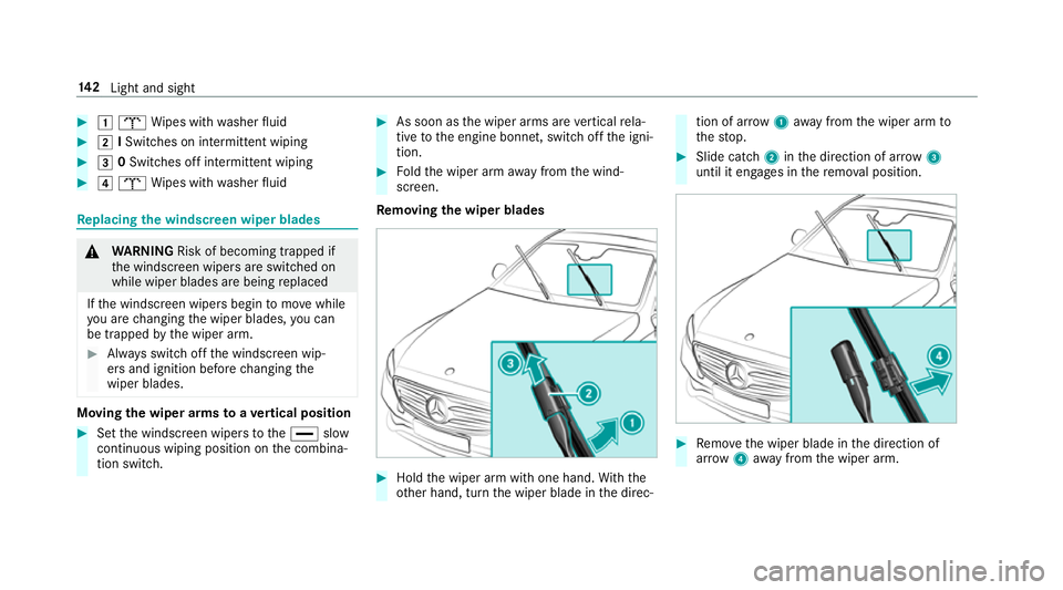
be trapped bythe wiper arm. #
Alw ays switch off the windscreen wip‐
ers and ignition before changing the
wiper blades. Moving
the wiper arms toave rtical position #
Set the windscreen wipers tothe° slow
continuous wiping position on the combina‐
tion switch. #
As soon as the wiper arms are vertical rela‐
tive tothe engine bonn et, switch off the igni‐
tion. #
Foldthe wiper arm away from the wind‐
screen.
Re moving the wiper blades #
Hold the wiper arm with one hand. With the
ot her hand, turn the wiper blade in the direc‐ tion of ar
row1away from the wiper arm to
th estop. #
Slide catch 2inthe direction of ar row 3
until it engages in there mo val position. #
Remo vethe wiper blade in the direction of
ar row 4away from the wiper arm. 14 2
Light and sight
Page 146 of 565
Fi
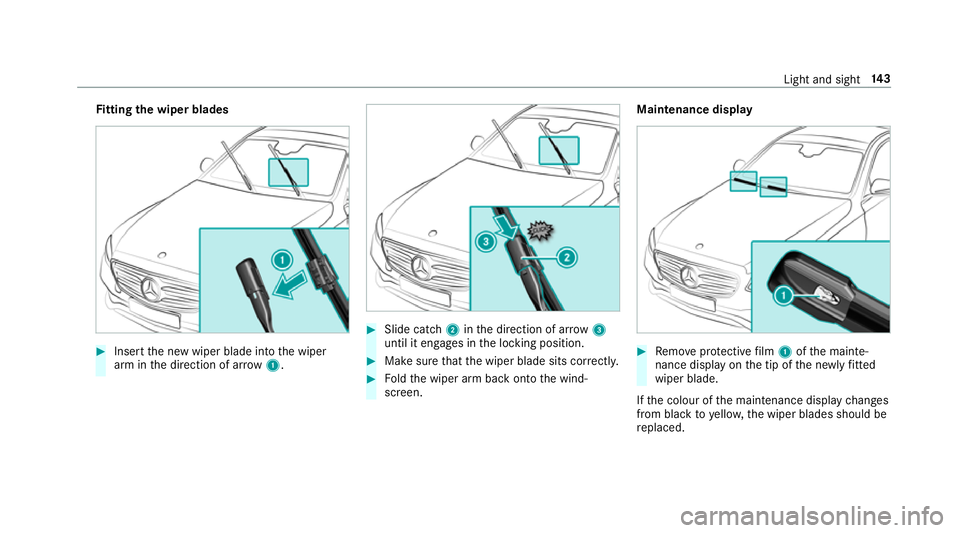
tting the wiper blades #
Inse rtthe new wiper blade into the wiper
arm in the direction of ar row1. #
Slide catch 2inthe direction of ar row 3
until it engages in the locking position. #
Make sure that the wiper blade sits cor rectly. #
Foldthe wiper arm back onto the wind‐
screen. Maintenance display
#
Remo veprotective film 1 ofthe mainte‐
nance display on the tip of the newly fitted
wiper blade.
If th e colour of the maintenance display changes
from black to yellow, the wiper blades should be
re placed. Light and sight
14 3
Page 147 of 565
%
The duration of the colour change varies
depending on the usage conditions. Re
placing the rear window wiper blades Re
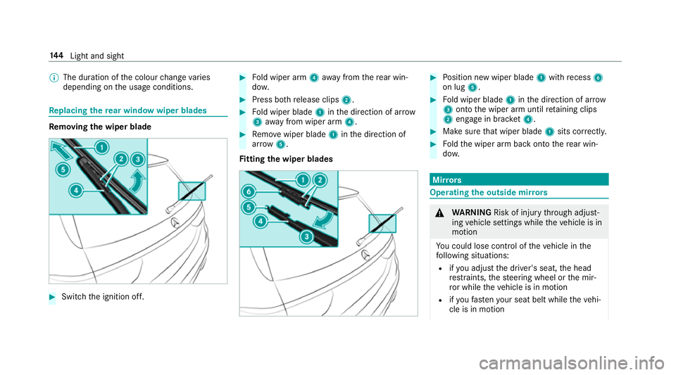
moving the wiper blade #
Switch the ignition off. #
Fold wiper arm 4away from there ar win‐
do w. #
Press bo threlease clips 2. #
Fold wiper blade 1inthe direction of ar row
3 away from wiper arm 4. #
Remo vewiper blade 1inthe direction of
ar row 5.
Fi tting the wiper blades #
Position new wiper blade 1with recess 6
on lug 5. #
Fold wiper blade 1inthe direction of ar row
3 onto the wiper arm until retaining clips
2 engage in brac ket4. #
Makesure that wiper blade 1sits cor rectl y. #
Foldthe wiper arm back onto there ar win‐
do w. Mir
rors Operating
the outside mir rors &
WARNING Risk of inju rythro ugh adjust‐
ing vehicle settings while theve hicle is in
motion
Yo u could lose cont rol of theve hicle in the
fo llowing situations:
R ifyo u adjust the driver's seat, the head
re stra ints, thesteering wheel or the mir‐
ro r while theve hicle is in motion
R ifyo ufast enyour seat belt while theve hi‐
cle is in motion 14 4
Light and sight
Page 148 of 565
#
Before starting the engine: adjust the
driver's seat, the head restra ints, the
st eering wheel or the mir ror and fasten
yo ur seat belt. &
WARNING Risk of accident due tomis‐
judgement of dis tances when using the
outside mir ror
The outside mir rors reflect objects on a
smaller scale. The objects in view are in fact
closer than they appear.
As a result, you may misjud gethe dis tance
between you and thero ad user driving
behind you, e.g. when changing lanes. #
Therefore, alw ays look over your shoul‐
der in order toensure that you are
aw are of the actual dis tance between
yo u and thero ad users driving behind
yo u. #
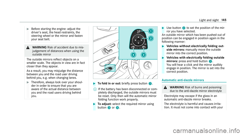
Tofold in or out: brieflypress button 1.
% Ifth e battery has been disconnected or com‐
ple tely discharged, the outside mir rors must
be reset. Only then will the automatic mir ror
fo lding function workproperly. #
Toadjus t:select therequ ired mir ror using
button 3or4. #
Use button 2toset the position of the mir‐
ro ryo u ha veselected.
An outside mir ror which has been pushed out of
position can be engaged in position again in the
fo llowing manner: #
Vehicles without electrical lyfolding out‐
side mir rors:manually mo vethe outside
mir ror into the cor rect position. #
Vehicles with electrical lyfolding outside
mir rors:press and hold button 1.
Yo u will hear a click and the mir ror audibly
engage in position. The mir ror is set into the
cor rect position. Au
tomatic anti-dazzle mir rors &
WARNING Risk of bu rns and poisoning
due tothe anti-dazzle mir ror electrolyte
Electrolyte may escape if theglass in an
automatic anti-dazzle mir ror breaks.
The electrolyte is harmful and causes ir rita‐
tion. It mu stnot come into contact wi thyour Light and sight
14 5
Page 149 of 565
skin,
eyes,respiratory organs or clo thing or
be swallo wed. #
Ifyo u come into contact with electro‐
ly te , obser vethefo llowing:
R Rinse the electrolyte from your skin
and seek medical attention immedi‐
atel y.
R If electrolyte comes into contact
with your eyes, rinse them thor‐
oughly with clean water and seek
medical attention immediately.
R Ifth e electrolyte is swallo wed,
immediately rinse your mouth out
th oroughly. Do not induce vomiting.
Seek medical attention immediately.
R Immedia tely ch ange out of clo thing
which has come into con tact wi th
electrolyte.
R If an allergic reaction occurs, seek
medical attention immediatel y.The outside mir
rors and inside rearview mir rors
on the driver's side automatically go into anti- dazzle mode if light from a headlamp hits
the
inside rearview mir ror.
Sy stem limitations
The mir rors do not go into anti-dazzle mode in
th efo llowing situations:
R the engine is switched off
R reve rsege ar is engaged
R interior lighting is swit ched on Pa
rking position of the passenger outside
mir ror The parking position makes parking easier.
The passenger outside mir ror tilts down wards
and sho wsthere ar wheel on the front passenger
side if:
R the parking position is stored
R the passenger mir ror is selected
R reve rsege ar is engaged
The passenger outside mir ror mo ves back toits
original position in thefo llowing situations: R
ifyo u shift the transmission toano ther trans‐
mission position
R when driving fasterthan 15 km/h
R ifyo u press the button forth e outside mir ror
on the driver's side Saving
the pa rking position of the passenger
outside mir ror Requ
irement:
Re versege ar must not be engaged when storing
using the memory button. 14 6
Light and sight
Page 150 of 565
#
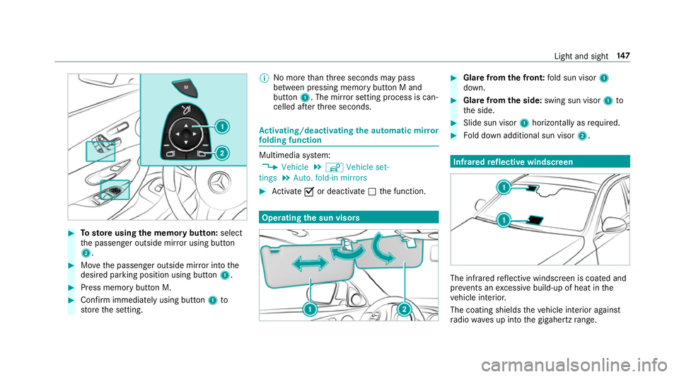
Tosto reusing the memory but ton: select
th e passenger outside mir ror using button
2. #
Movethe passenger outside mir ror into the
desired parking position using button 1.#
Press memory button M. #
Confirm immediately using button 1to
st ore the setting. %
No more than thre e seconds may pass
between pressing memory button M and
button 1. The mir ror setting process is can‐
celled af terth re e seconds. Ac
tivating/deactivating the automatic mir ror
fo lding function Multimedia sy
stem:
, Vehicle .
î Vehicle set-
tings .
Auto. fold-in mirrors #
Activate Oor deacti vate ª the function. Operating
the sun visors #
Glarefrom the front: fold sun visor 1
down. #
Glare from the side: swing sun visor 1to
th e side. #
Slide sun visor 1horizon tally as required. #
Fold down additional sun visor 2. Infrared
reflective windscreen The inf
rare dre flective windscreen is coated and
pr eve nts an excessive build-up of heat in the
ve hicle interior.
The coating shields theve hicle interior against
ra dio waves up into the gigahertz range. Light and sight
147