MERCEDES-BENZ SPRINTER 2005 Service Repair Manual
Manufacturer: MERCEDES-BENZ, Model Year: 2005, Model line: SPRINTER, Model: MERCEDES-BENZ SPRINTER 2005Pages: 1232, PDF Size: 39.23 MB
Page 1141 of 1232
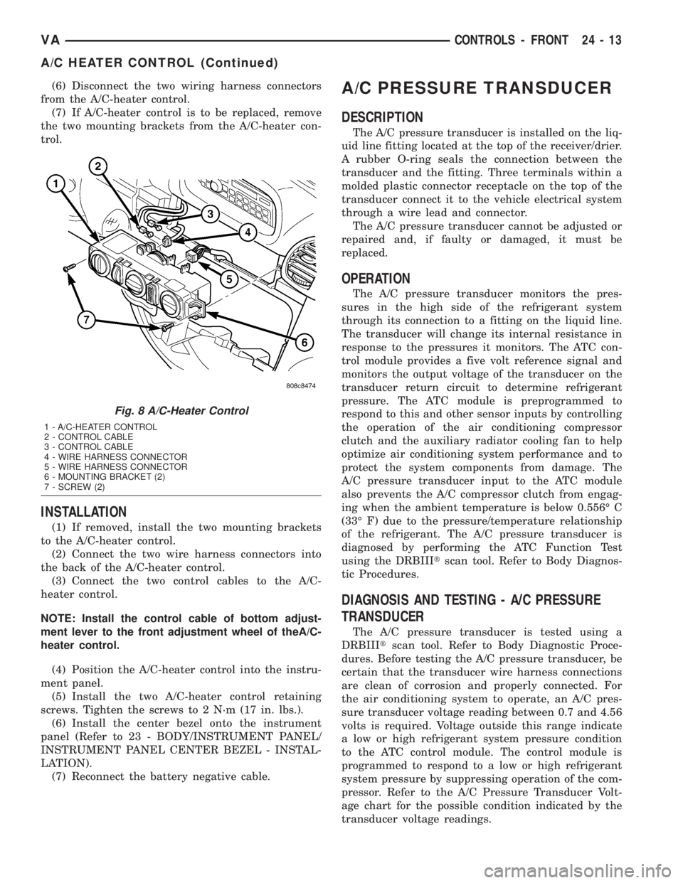
(6) Disconnect the two wiring harness connectors
from the A/C-heater control.
(7) If A/C-heater control is to be replaced, remove
the two mounting brackets from the A/C-heater con-
trol.
INSTALLATION
(1) If removed, install the two mounting brackets
to the A/C-heater control.
(2) Connect the two wire harness connectors into
the back of the A/C-heater control.
(3) Connect the two control cables to the A/C-
heater control.
NOTE: Install the control cable of bottom adjust-
ment lever to the front adjustment wheel of theA/C-
heater control.
(4) Position the A/C-heater control into the instru-
ment panel.
(5) Install the two A/C-heater control retaining
screws. Tighten the screws to 2 N´m (17 in. lbs.).
(6) Install the center bezel onto the instrument
panel (Refer to 23 - BODY/INSTRUMENT PANEL/
INSTRUMENT PANEL CENTER BEZEL - INSTAL-
LATION).
(7) Reconnect the battery negative cable.
A/C PRESSURE TRANSDUCER
DESCRIPTION
The A/C pressure transducer is installed on the liq-
uid line fitting located at the top of the receiver/drier.
A rubber O-ring seals the connection between the
transducer and the fitting. Three terminals within a
molded plastic connector receptacle on the top of the
transducer connect it to the vehicle electrical system
through a wire lead and connector.
The A/C pressure transducer cannot be adjusted or
repaired and, if faulty or damaged, it must be
replaced.
OPERATION
The A/C pressure transducer monitors the pres-
sures in the high side of the refrigerant system
through its connection to a fitting on the liquid line.
The transducer will change its internal resistance in
response to the pressures it monitors. The ATC con-
trol module provides a five volt reference signal and
monitors the output voltage of the transducer on the
transducer return circuit to determine refrigerant
pressure. The ATC module is preprogrammed to
respond to this and other sensor inputs by controlling
the operation of the air conditioning compressor
clutch and the auxiliary radiator cooling fan to help
optimize air conditioning system performance and to
protect the system components from damage. The
A/C pressure transducer input to the ATC module
also prevents the A/C compressor clutch from engag-
ing when the ambient temperature is below 0.556É C
(33É F) due to the pressure/temperature relationship
of the refrigerant. The A/C pressure transducer is
diagnosed by performing the ATC Function Test
using the DRBIIItscan tool. Refer to Body Diagnos-
tic Procedures.
DIAGNOSIS AND TESTING - A/C PRESSURE
TRANSDUCER
The A/C pressure transducer is tested using a
DRBIIItscan tool. Refer to Body Diagnostic Proce-
dures. Before testing the A/C pressure transducer, be
certain that the transducer wire harness connections
are clean of corrosion and properly connected. For
the air conditioning system to operate, an A/C pres-
sure transducer voltage reading between 0.7 and 4.56
volts is required. Voltage outside this range indicate
a low or high refrigerant system pressure condition
to the ATC control module. The control module is
programmed to respond to a low or high refrigerant
system pressure by suppressing operation of the com-
pressor. Refer to the A/C Pressure Transducer Volt-
age chart for the possible condition indicated by the
transducer voltage readings.
Fig. 8 A/C-Heater Control
1 - A/C-HEATER CONTROL
2 - CONTROL CABLE
3 - CONTROL CABLE
4 - WIRE HARNESS CONNECTOR
5 - WIRE HARNESS CONNECTOR
6 - MOUNTING BRACKET (2)
7 - SCREW (2)
VACONTROLS - FRONT 24 - 13
A/C HEATER CONTROL (Continued)
Page 1142 of 1232
A/C PRESSURE TRANSDUCER VOLTAGE
Voltage Possible Cause
0.0 1. No transducer supply voltage from ATC control module.
2. Shorted transducer circuit.
3. Faulty transducer.
0.150 to 0.450 1. Ambient temperature below 10É C (50É F).
2. Low refrigerant system pressure.
0.451 to 4.519 1. Normal refrigerant system pressure.
4.520 to 4.850 1. High refrigerant system pressure.
5.0 1. Open transducer circuit.
2. Faulty transducer.
REMOVAL
WARNING: REFER TO THE APPLICABLE WARN-
INGS AND CAUTIONS FOR THIS SYSTEM BEFORE
PERFORMING THE FOLLOWING OPERATION (Refer
to 24 - HEATING & AIR CONDITIONING/PLUMBING -
WARNING) and (Refer to 24 - HEATING & AIR CON-
DITIONING/PLUMBING - CAUTION).
(1) Recover the refrigerant from the refrigerant
system (Refer to 24 - HEATING & AIR CONDITION-
ING/PLUMBING - STANDARD PROCEDURE).
(2) Disconnect and isolate the battery negative
cable.
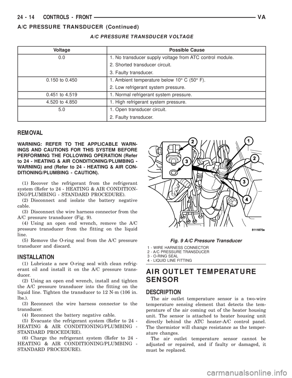
(3) Disconnect the wire harness connector from the
A/C pressure transducer (Fig. 9).
(4) Using an open end wrench, remove the A/C
pressure transducer from the fitting on the liquid
line.
(5) Remove the O-ring seal from the A/C pressure
transducer and discard.
INSTALLATION
(1) Lubricate a new O-ring seal with clean refrig-
erant oil and install it on the A/C pressure trans-
ducer.
(2) Using an open end wrench, install and tighten
the A/C pressure transducer into the fitting on the
liquid line. Tighten the transducer to 12 N´m (106 in.
lbs.).
(3) Reconnect the wire harness connector to the
transducer.
(4) Reconnect the battery negative cable.
(5) Evacuate the refrigerant system (Refer to 24 -
HEATING & AIR CONDITIONING/PLUMBING -
STANDARD PROCEDURE).
(6) Charge the refrigerant system (Refer to 24 -
HEATING & AIR CONDITIONING/PLUMBING -
STANDARD PROCEDURE).
AIR OUTLET TEMPERATURE
SENSOR
DESCRIPTION
The air outlet temperature sensor is a two-wire
temperature sensing element that detects the tem-
perature of the air coming out of the heater housing
unit. The sensor is attached to heater housing unit
directly behind the ATC heater-A/C control panel.
The thermistor will change resistance as the temper-
ature changes.
The air outlet temperature sensor cannot be
adjusted or repaired, and if faulty or damaged, it
must be replaced.
Fig. 9 A/C Pressure Transducer
1 - WIRE HARNESS CONNECTOR
2 - A/C PRESSURE TRANSDUCER
3 - O-RING SEAL
4 - LIQUID LINE FITTING
24 - 14 CONTROLS - FRONTVA
A/C PRESSURE TRANSDUCER (Continued)
Page 1143 of 1232
OPERATION
The air outlet temperature sensor monitors the
temperature of the air coming out of the heater hous-
ing unit. The sensor will change its internal resis-
tance in response to the temperatures it monitors.
The ATC control module is connected to the sensor
through a sensor ground circuit and a sensor signal
circuit. As the air temperature increases, the resis-
tance of the sensor decreases and the voltage moni-
tored by the module decreases. The module uses this
monitored voltage reading to an indication of the out-
let air temperature. The ATC control module makes
adjustments to maintain the requested interior tem-
perature by cycling both the A/C compressor and
solenoid heater valve on and off.
The air outlet temperature sensor is diagnosed by
performing the ATC Function Test using the DRBIIIt
scan tool. Refer to Body Diagnostic Procedures.
REMOVAL
(1) Disconnect and isolate the battery negative
cable.
(2) Remove the heater-A/C control from the instru-
ment panel (Refer to 24 - HEATING & AIR CONDI-
TIONING/CONTROLS/A/C HEATER CONTROL -
REMOVAL).
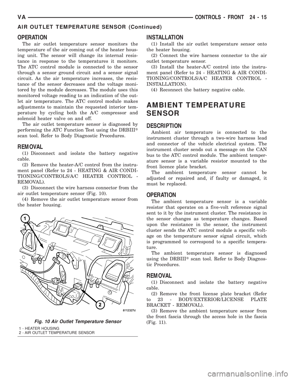
(3) Disconnect the wire harness connector from the
air outlet temperature sensor (Fig. 10).
(4) Remove the air outlet temperature sensor from
the heater housing.
INSTALLATION
(1) Install the air outlet temperature sensor onto
the heater housing.
(2) Connect the wire harness connector to the air
outlet temperature sensor.
(3) Install the heater-A/C control into the instru-
ment panel (Refer to 24 - HEATING & AIR CONDI-
TIONING/CONTROLS/A/C HEATER CONTROL -
INSTALLATION).
(4) Reconnect the battery negative cable.
AMBIENT TEMPERATURE
SENSOR
DESCRIPTION
Ambient air temperature is connected to the
instrument cluster through a two-wire harness lead
and connector of the vehicle electrical system. The
instrument cluster sends out a message on the CAN
bus to the ATC control module. The ambient temper-
ature sensor is a variable resistor mounted to the
front licence plate bracket.
The ambient temperature sensor cannot be
adjusted or repaired and, if faulty or damaged, it
must be replaced.
OPERATION
The ambient temperature sensor is a variable
resistor that operates on a five-volt reference signal
sent to it by the instrument cluster. The resistance in
the sensor changes as temperature changes. Based
upon the resistance in the sensor, the instrument
cluster sends the ATC control module a specific volt-
age on the temperature sensor signal circuit, which
is programmed to correspond to a specific tempera-
ture.
The ambient temperature sensor is diagnosed
using the DRBIIItscan tool. Refer to Body Diagnos-
tic Procedures.
REMOVAL
(1) Disconnect and isolate the battery negative
cable.
(2) Remove the front license plate bracket (Refer
to 23 - BODY/EXTERIOR/LICENSE PLATE
BRACKET - REMOVAL).
(3) Remove the ambient temperature sensor from
the front fascia through the access hole in the fascia
(Fig. 11).
Fig. 10 Air Outlet Temperature Sensor
1 - HEATER HOUSING
2 - AIR OUTLET TEMPERATURE SENSOR
VACONTROLS - FRONT 24 - 15
AIR OUTLET TEMPERATURE SENSOR (Continued)
Page 1144 of 1232
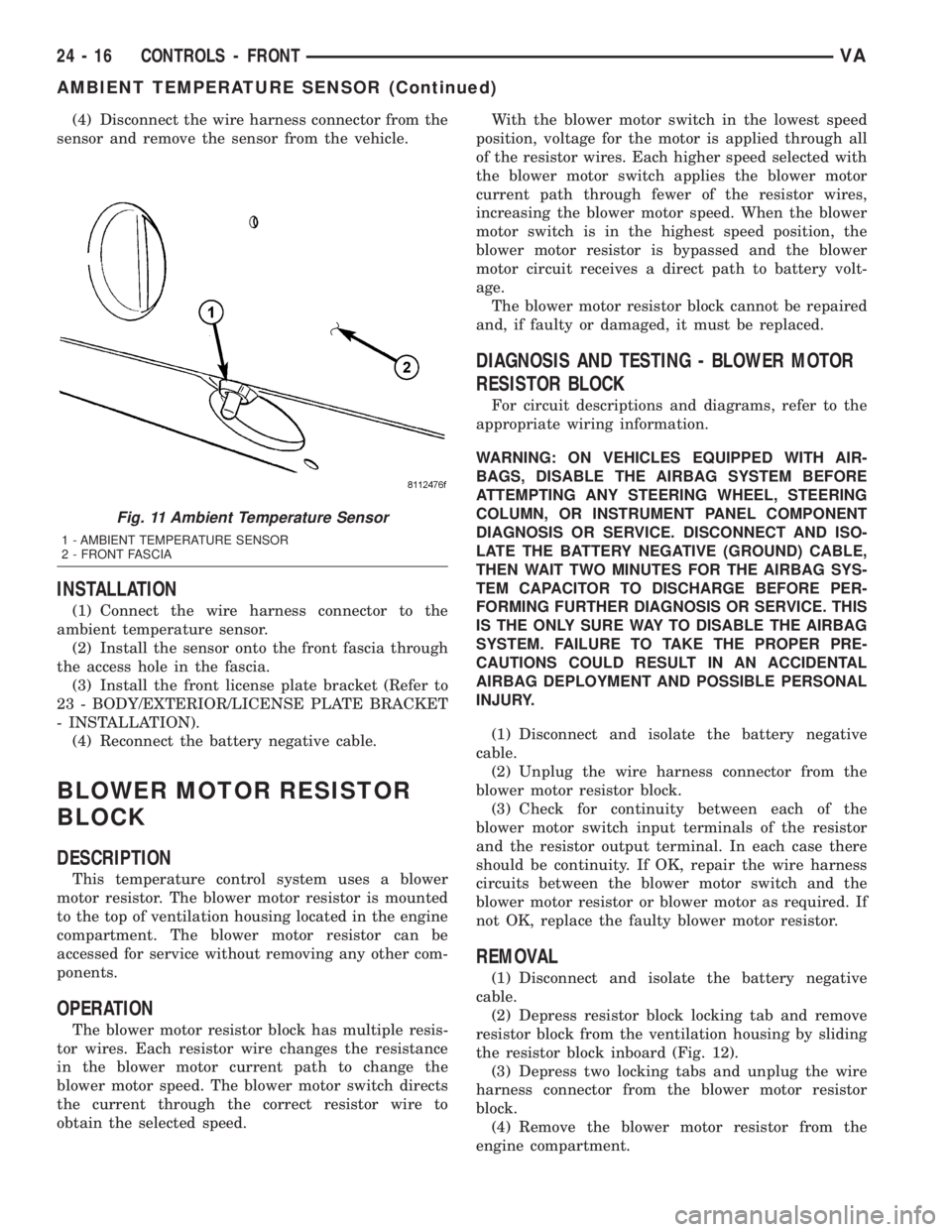
(4) Disconnect the wire harness connector from the
sensor and remove the sensor from the vehicle.
INSTALLATION
(1) Connect the wire harness connector to the
ambient temperature sensor.
(2) Install the sensor onto the front fascia through
the access hole in the fascia.
(3) Install the front license plate bracket (Refer to
23 - BODY/EXTERIOR/LICENSE PLATE BRACKET
- INSTALLATION).
(4) Reconnect the battery negative cable.
BLOWER MOTOR RESISTOR
BLOCK
DESCRIPTION
This temperature control system uses a blower
motor resistor. The blower motor resistor is mounted
to the top of ventilation housing located in the engine
compartment. The blower motor resistor can be
accessed for service without removing any other com-
ponents.
OPERATION
The blower motor resistor block has multiple resis-
tor wires. Each resistor wire changes the resistance
in the blower motor current path to change the
blower motor speed. The blower motor switch directs
the current through the correct resistor wire to
obtain the selected speed.With the blower motor switch in the lowest speed
position, voltage for the motor is applied through all
of the resistor wires. Each higher speed selected with
the blower motor switch applies the blower motor
current path through fewer of the resistor wires,
increasing the blower motor speed. When the blower
motor switch is in the highest speed position, the
blower motor resistor is bypassed and the blower
motor circuit receives a direct path to battery volt-
age.
The blower motor resistor block cannot be repaired
and, if faulty or damaged, it must be replaced.
DIAGNOSIS AND TESTING - BLOWER MOTOR
RESISTOR BLOCK
For circuit descriptions and diagrams, refer to the
appropriate wiring information.
WARNING: ON VEHICLES EQUIPPED WITH AIR-
BAGS, DISABLE THE AIRBAG SYSTEM BEFORE
ATTEMPTING ANY STEERING WHEEL, STEERING
COLUMN, OR INSTRUMENT PANEL COMPONENT
DIAGNOSIS OR SERVICE. DISCONNECT AND ISO-
LATE THE BATTERY NEGATIVE (GROUND) CABLE,
THEN WAIT TWO MINUTES FOR THE AIRBAG SYS-
TEM CAPACITOR TO DISCHARGE BEFORE PER-
FORMING FURTHER DIAGNOSIS OR SERVICE. THIS
IS THE ONLY SURE WAY TO DISABLE THE AIRBAG
SYSTEM. FAILURE TO TAKE THE PROPER PRE-
CAUTIONS COULD RESULT IN AN ACCIDENTAL
AIRBAG DEPLOYMENT AND POSSIBLE PERSONAL
INJURY.
(1) Disconnect and isolate the battery negative
cable.
(2) Unplug the wire harness connector from the
blower motor resistor block.
(3) Check for continuity between each of the
blower motor switch input terminals of the resistor
and the resistor output terminal. In each case there
should be continuity. If OK, repair the wire harness
circuits between the blower motor switch and the
blower motor resistor or blower motor as required. If
not OK, replace the faulty blower motor resistor.
REMOVAL
(1) Disconnect and isolate the battery negative
cable.
(2) Depress resistor block locking tab and remove
resistor block from the ventilation housing by sliding
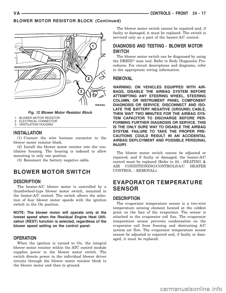
the resistor block inboard (Fig. 12).
(3) Depress two locking tabs and unplug the wire
harness connector from the blower motor resistor
block.
(4) Remove the blower motor resistor from the
engine compartment.
Fig. 11 Ambient Temperature Sensor
1 - AMBIENT TEMPERATURE SENSOR
2 - FRONT FASCIA
24 - 16 CONTROLS - FRONTVA
AMBIENT TEMPERATURE SENSOR (Continued)
Page 1145 of 1232
INSTALLATION
(1) Connect the wire harness connector to the
blower motor resistor block.
(2) Install the blower motor resistor into the ven-
tilation housing. The housing is indexed to allow
mounting in only one position.
(3) Reconnect the battery negative cable.
BLOWER MOTOR SWITCH
DESCRIPTION
The heater-A/C blower motor is controlled by a
thumbwheel-type blower motor switch, mounted in
the heater-A/C control. The switch allows the selec-
tion of four blower motor speeds with the ignition
switch in the On position.
NOTE: The blower motor will operate only at the
lowest speed when the Residual Engine Heat Utili-
zation (REST) function is selected, regardless of the
blower speed setting on the control panel.
OPERATION
When the ignition is turned to On, the integral
blower motor resistor within the ATC control module
supplies power to the blower motor switch. The
switch directs power to the individual blower driver
circuits through the blower motor resistor block to
the blower motor and then to ground.The blower motor switch cannot be repaired and, if
faulty or damaged, it must be replaced. The switch is
serviced only as a part of the heater-A/C control.
DIAGNOSIS AND TESTING - BLOWER MOTOR
SWITCH
The blower motor switch can be diagnosed by using
the DRBIIItscan tool. Refer to Body Diagnostic Pro-
cedures. For circuit descriptions and diagrams, refer
to the appropriate wiring information.
REMOVAL
WARNING: ON VEHICLES EQUIPPED WITH AIR-
BAGS, DISABLE THE AIRBAG SYSTEM BEFORE
ATTEMPTING ANY STEERING WHEEL, STEERING
COLUMN, OR INSTRUMENT PANEL COMPONENT
DIAGNOSIS OR SERVICE. DISCONNECT AND ISO-
LATE THE BATTERY NEGATIVE (GROUND) CABLE,
THEN WAIT TWO MINUTES FOR THE AIRBAG SYS-
TEM CAPACITOR TO DISCHARGE BEFORE PER-
FORMING FURTHER DIAGNOSIS OR SERVICE. THIS
IS THE ONLY SURE WAY TO DISABLE THE AIRBAG
SYSTEM. FAILURE TO TAKE THE PROPER PRE-
CAUTIONS COULD RESULT IN AN ACCIDENTAL
AIRBAG DEPLOYMENT AND POSSIBLE PERSONAL
INJURY.
The blower motor switch cannot be adjusted or
repaired, and if faulty or damaged, the heater-A/C
control must be replaced (Refer to 24 - HEATING &
AIR CONDITIONING/CONTROLS/A/C HEATER
CONTROL - REMOVAL).
EVAPORATOR TEMPERATURE
SENSOR
DESCRIPTION
The evaporator temperature sensor is a two-wire
temperature sensing element located at the coldest
point on the face of the evaporator. The sensor is
attached to the evaporator coil fins. The evaporator
temperature sensor prevents condensation on the
evaporator coil from freezing and obstructing A/C
system air flow. The evaporator temperature sensor
cannot be adjusted or repaired and, if faulty or dam-
aged, it must be replaced.
Fig. 12 Blower Motor Resistor Block
1 - BLOWER MOTOR RESISTOR
2 - ELECTRICAL CONNECTOR
3 - VENTILATION HOUSING
VACONTROLS - FRONT 24 - 17
BLOWER MOTOR RESISTOR BLOCK (Continued)
Page 1146 of 1232
OPERATION
The evaporator temperature sensor monitors the
temperature of the evaporator. The sensor will
change its internal resistance in response to the tem-
peratures it monitors. The ATC control module is
connected to the sensor through a sensor ground cir-
cuit and a sensor signal circuit. As the evaporator
temperature increases, the resistance of the sensor
decreases and the voltage monitored by the module
decreases. The module uses this monitored voltage
reading to an indication of the evaporator tempera-
ture. The ATC control module is programmed to
respond to this input by cycling the air conditioning
compressor clutch as necessary to optimize air condi-
tioning system performance and to protect the sys-
tem from evaporator freezing. The external location
of the sensor allows the sensor to be removed or
installed without disturbing the refrigerant in the
system. The evaporator temperature sensor is diag-
nosed by performing the ATC Function Test using a
DRBIIItscan tool. Refer to Body Diagnostic Proce-
dures.
REMOVAL
(1) Disconnect and isolate the battery negative
cable.
(2) Remove the radio (Refer to 8 - ELECTRICAL/
AUDIO/RADIO - REMOVAL).
(3) Remove glove compartment.
(4) Remove cover from instrument cluster (Refer to
23 - BODY/INSTRUMENT PANEL/INSTRUMENT
PANEL TOP COVER - REMOVAL).
(5) Remove the instrument cluster (Refer to 8 -
ELECTRICAL/INSTRUMENT CLUSTER - REMOV-
AL).
(6) Remove passenger side airbag.
(7) Remove cover above air nozzle on passenger
side.
(8) Remove speaker.
(9) Remove center section of instrument panel.
(10) Remove heater-A/C control from the instru-
ment panel (Refer to 24 - HEATING & AIR CONDI-
TIONING/CONTROLS/A/C HEATER CONTROL -
REMOVAL).
(11) Remove instrument panel top section.
(12) Remove electrical connections.
(13) Remove air bezels from instrument panel.
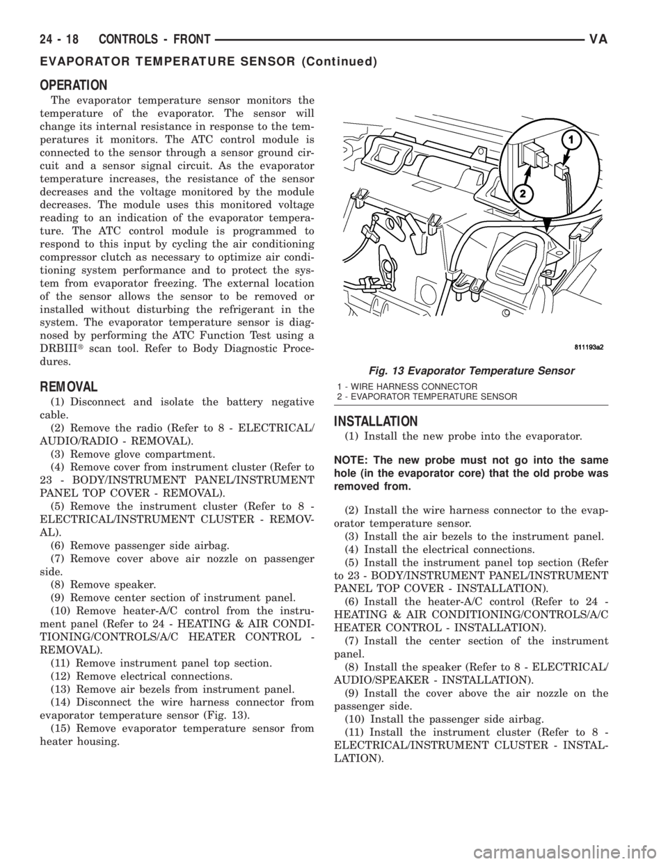
(14) Disconnect the wire harness connector from
evaporator temperature sensor (Fig. 13).
(15) Remove evaporator temperature sensor from
heater housing.
INSTALLATION
(1) Install the new probe into the evaporator.
NOTE: The new probe must not go into the same
hole (in the evaporator core) that the old probe was
removed from.
(2) Install the wire harness connector to the evap-
orator temperature sensor.
(3) Install the air bezels to the instrument panel.
(4) Install the electrical connections.
(5) Install the instrument panel top section (Refer
to 23 - BODY/INSTRUMENT PANEL/INSTRUMENT
PANEL TOP COVER - INSTALLATION).
(6) Install the heater-A/C control (Refer to 24 -
HEATING & AIR CONDITIONING/CONTROLS/A/C
HEATER CONTROL - INSTALLATION).
(7) Install the center section of the instrument
panel.
(8) Install the speaker (Refer to 8 - ELECTRICAL/
AUDIO/SPEAKER - INSTALLATION).
(9) Install the cover above the air nozzle on the
passenger side.
(10) Install the passenger side airbag.
(11) Install the instrument cluster (Refer to 8 -
ELECTRICAL/INSTRUMENT CLUSTER - INSTAL-
LATION).
Fig. 13 Evaporator Temperature Sensor
1 - WIRE HARNESS CONNECTOR
2 - EVAPORATOR TEMPERATURE SENSOR
24 - 18 CONTROLS - FRONTVA
EVAPORATOR TEMPERATURE SENSOR (Continued)
Page 1147 of 1232
(12) Install the cover to the instrument cluster.
(13) Install glove compartment.
(14) Install the radio (Refer to 8 - ELECTRICAL/
AUDIO/RADIO - INSTALLATION).
(15) Reconnect the battery negative cable.
IN-CAR TEMPERATURE
SENSOR
DESCRIPTION
The in-car temperature sensor measures the actual
air temperature within the passenger compartment.
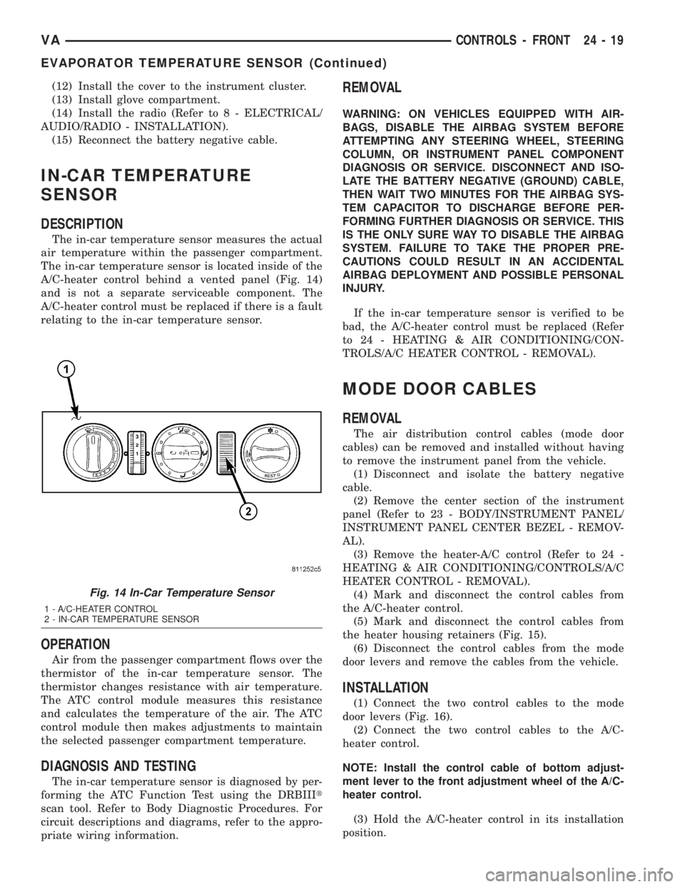
The in-car temperature sensor is located inside of the
A/C-heater control behind a vented panel (Fig. 14)
and is not a separate serviceable component. The
A/C-heater control must be replaced if there is a fault
relating to the in-car temperature sensor.
OPERATION
Air from the passenger compartment flows over the
thermistor of the in-car temperature sensor. The
thermistor changes resistance with air temperature.
The ATC control module measures this resistance
and calculates the temperature of the air. The ATC
control module then makes adjustments to maintain
the selected passenger compartment temperature.
DIAGNOSIS AND TESTING
The in-car temperature sensor is diagnosed by per-
forming the ATC Function Test using the DRBIIIt
scan tool. Refer to Body Diagnostic Procedures. For
circuit descriptions and diagrams, refer to the appro-
priate wiring information.
REMOVAL
WARNING: ON VEHICLES EQUIPPED WITH AIR-
BAGS, DISABLE THE AIRBAG SYSTEM BEFORE
ATTEMPTING ANY STEERING WHEEL, STEERING
COLUMN, OR INSTRUMENT PANEL COMPONENT
DIAGNOSIS OR SERVICE. DISCONNECT AND ISO-
LATE THE BATTERY NEGATIVE (GROUND) CABLE,
THEN WAIT TWO MINUTES FOR THE AIRBAG SYS-
TEM CAPACITOR TO DISCHARGE BEFORE PER-
FORMING FURTHER DIAGNOSIS OR SERVICE. THIS
IS THE ONLY SURE WAY TO DISABLE THE AIRBAG
SYSTEM. FAILURE TO TAKE THE PROPER PRE-
CAUTIONS COULD RESULT IN AN ACCIDENTAL
AIRBAG DEPLOYMENT AND POSSIBLE PERSONAL
INJURY.
If the in-car temperature sensor is verified to be
bad, the A/C-heater control must be replaced (Refer
to 24 - HEATING & AIR CONDITIONING/CON-
TROLS/A/C HEATER CONTROL - REMOVAL).
MODE DOOR CABLES
REMOVAL
The air distribution control cables (mode door
cables) can be removed and installed without having
to remove the instrument panel from the vehicle.
(1) Disconnect and isolate the battery negative
cable.
(2) Remove the center section of the instrument
panel (Refer to 23 - BODY/INSTRUMENT PANEL/
INSTRUMENT PANEL CENTER BEZEL - REMOV-
AL).
(3) Remove the heater-A/C control (Refer to 24 -
HEATING & AIR CONDITIONING/CONTROLS/A/C
HEATER CONTROL - REMOVAL).
(4) Mark and disconnect the control cables from
the A/C-heater control.
(5) Mark and disconnect the control cables from
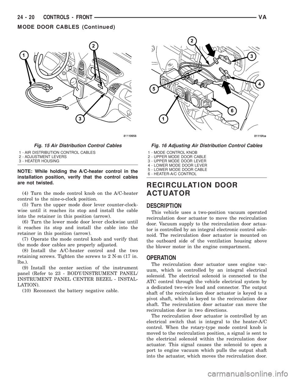
the heater housing retainers (Fig. 15).
(6) Disconnect the control cables from the mode
door levers and remove the cables from the vehicle.
INSTALLATION
(1) Connect the two control cables to the mode
door levers (Fig. 16).
(2) Connect the two control cables to the A/C-
heater control.
NOTE: Install the control cable of bottom adjust-
ment lever to the front adjustment wheel of the A/C-
heater control.
(3) Hold the A/C-heater control in its installation
position.
Fig. 14 In-Car Temperature Sensor
1 - A/C-HEATER CONTROL
2 - IN-CAR TEMPERATURE SENSOR
VACONTROLS - FRONT 24 - 19
EVAPORATOR TEMPERATURE SENSOR (Continued)
Page 1148 of 1232
NOTE: While holding the A/C-heater control in the
installation position, verify that the control cables
are not twisted.
(4) Turn the mode control knob on the A/C-heater
control to the nine-o-clock position.
(5) Turn the upper mode door lever counter-clock-
wise until it reaches its stop and install the cable
into the retainer in this position (arrow).
(6) Turn the lower mode door lever clockwise until
it reaches its stop and install the cable into the
retainer in this position (arrow).
(7) Operate the mode control knob and verify that
the mode door cables are properly adjusted.
(8) Install the A/C-heater control and the two
retaining screws. Tighten the screws to 2 N´m (17 in.
lbs.).
(9) Install the center section of the instrument
panel (Refer to 23 - BODY/INSTRUMENT PANEL/
INSTRUMENT PANEL CENTER BEZEL - INSTAL-
LATION).
(10) Reconnect the battery negative cable.
RECIRCULATION DOOR
ACTUATOR
DESCRIPTION
This vehicle uses a two-position vacuum operated
recirculation door actuator to move the recirculation
door. Vacuum supply to the recirculation door actua-
tor is controlled by an integral electronic control sole-
noid. The recirculation door actuator is mounted on
the outboard side of the ventilation housing above
the blower motor in the engine compartment.
OPERATION
The recirculation door actuator uses engine vac-
uum, which is controlled by an integral electrical
solenoid. The electrical solenoid is connected to the
ATC control through the vehicle electrical system by
a dedicated two-wire lead and connector. The output
shaft of the recirculation door actuator is keyed to a
pivot shaft, which is keyed to the recirculation door
shaft. The recirculation door actuator can move the
recirculation door in two directions.
The recirculation door actuator is controlled by an
electrical switch that is integral to the heater-A/C
control. When the rotary-type mode control knob is
moved to the recirculation position, a signal is sent to
the electrical solenoid within the recirculation door
actuator. This signal causes the solenoid to open a
port to engine vacuum which pulls the output shaft
into the actuator, which moves the recirculation door.
Fig. 15 Air Distribution Control Cables
1 - AIR DISTRIBUTION CONTROL CABLES
2 - ADJUSTMENT LEVERS
3 - HEATER HOUSING
Fig. 16 Adjusting Air Distribution Control Cables
1 - MODE CONTROL KNOB
2 - UPPER MODE DOOR CABLE
3 - UPPER MODE DOOR LEVER
4 - LOWER MODE DOOR LEVER
5 - LOWER MODE DOOR CABLE
6 - HEATER-A/C CONTROL
24 - 20 CONTROLS - FRONTVA
MODE DOOR CABLES (Continued)
Page 1149 of 1232
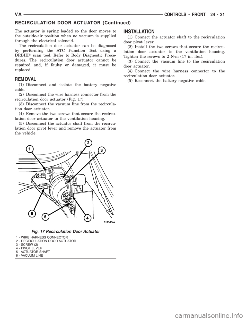
The actuator is spring loaded so the door moves to
the outside-air position when no vacuum is supplied
through the electrical solenoid.
The recirculation door actuator can be diagnosed
by performing the ATC Function Test using a
DRBIIItscan tool. Refer to Body Diagnostic Proce-
dures. The recirculation door actuator cannot be
repaired and, if faulty or damaged, it must be
replaced.
REMOVAL
(1) Disconnect and isolate the battery negative
cable.
(2) Disconnect the wire harness connector from the
recirculation door actuator (Fig. 17).
(3) Disconnect the vacuum line from the recircula-
tion door actuator.
(4) Remove the two screws that secure the recircu-
lation door actuator to the ventilation housing.
(5) Disconnect the actuator shaft from the recircu-
lation door pivot lever and remove the actuator from
the vehicle.
INSTALLATION
(1) Connect the actuator shaft to the recirculation
door pivot lever.
(2) Install the two screws that secure the recircu-
lation door actuator to the ventilation housing.
Tighten the screws to 2 N´m (17 in. lbs.).
(3) Connect the vacuum line to the recirculation
door actuator.
(4) Connect the wire harness connector to the
recirculation door actuator.
(5) Reconnect the battery negative cable.
Fig. 17 Recirculation Door Actuator
1 - WIRE HARNESS CONNECTOR
2 - RECIRCULATION DOOR ACTUATOR
3 - SCREW (2)
4 - PIVOT LEVER
5 - ACTUATOR SHAFT
6 - VACUUM LINE
VACONTROLS - FRONT 24 - 21
RECIRCULATION DOOR ACTUATOR (Continued)
Page 1150 of 1232
CONTROLS - REAR
TABLE OF CONTENTS
page page
BLOWER MOTOR SWITCH
DESCRIPTION.........................22
OPERATION...........................22
DIAGNOSIS AND TESTING................23
REMOVAL.............................23
INSTALLATION.........................23
BLOWER MOTOR RELAY
DESCRIPTION.........................23
OPERATION...........................23
DIAGNOSIS AND TESTING................24
REMOVAL.............................24
INSTALLATION.........................24
CONTROL MODULE
DESCRIPTION.........................24
OPERATION...........................24
DIAGNOSIS AND TESTING................24
REMOVAL.............................24
INSTALLATION.........................25
EVAPORATOR TEMPERATURE SENSOR
DESCRIPTION.........................25
OPERATION...........................26DIAGNOSIS AND TESTING................26
REMOVAL.............................26
INSTALLATION.........................26
SOLENOID VALVE
DESCRIPTION.........................27
OPERATION...........................27
DIAGNOSIS AND TESTING................27
REMOVAL.............................27
INSTALLATION.........................28
TEMPERATURE CONTROL
DESCRIPTION.........................29
OPERATION...........................29
DIAGNOSIS AND TESTING................29
REMOVAL.............................29
INSTALLATION.........................29
TEMPERATURE SENSOR
DESCRIPTION.........................30
OPERATION...........................30
DIAGNOSIS AND TESTING................30
REMOVAL.............................30
INSTALLATION.........................30
BLOWER MOTOR SWITCH
DESCRIPTION
The optional rear A/C unit blower motor is con-
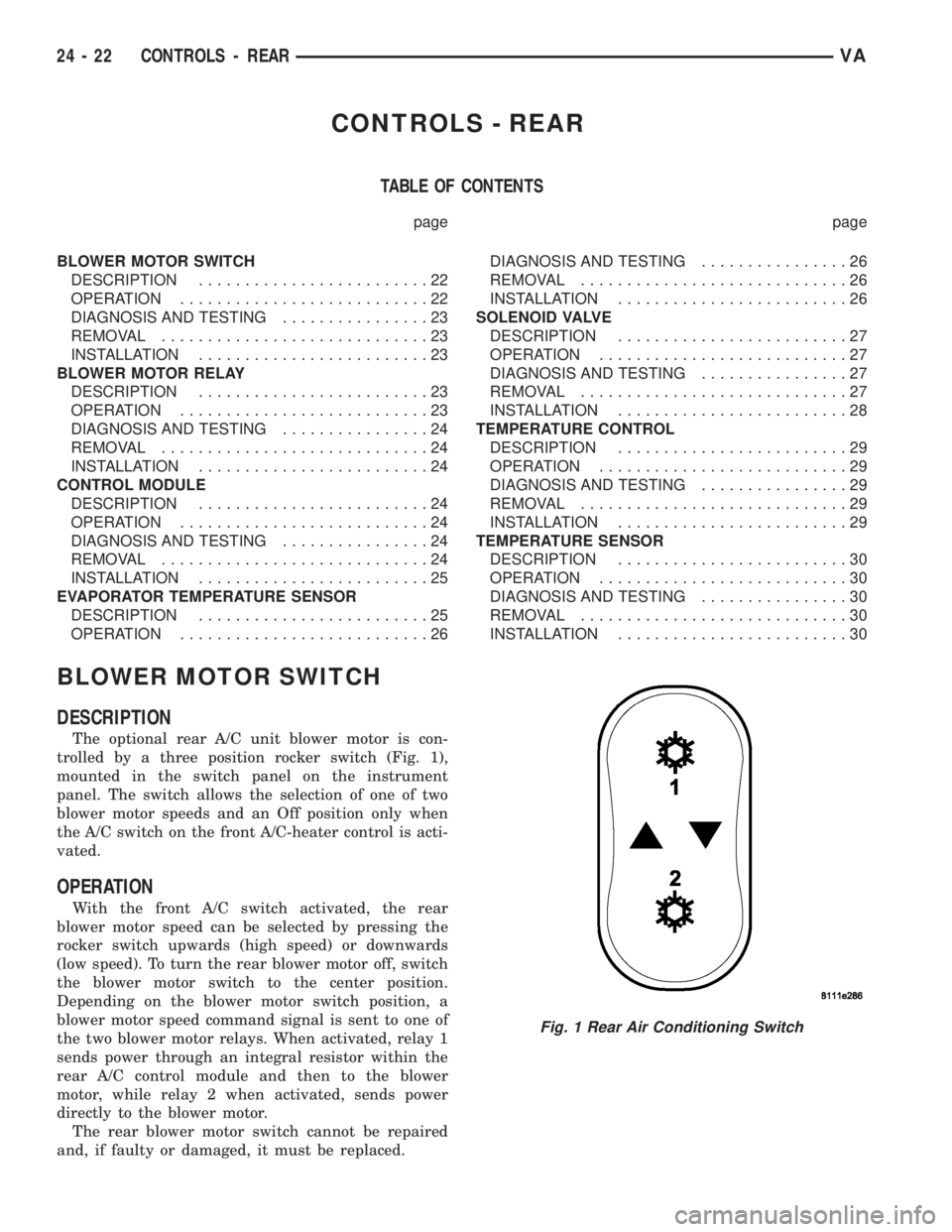
trolled by a three position rocker switch (Fig. 1),
mounted in the switch panel on the instrument
panel. The switch allows the selection of one of two
blower motor speeds and an Off position only when
the A/C switch on the front A/C-heater control is acti-
vated.
OPERATION
With the front A/C switch activated, the rear
blower motor speed can be selected by pressing the
rocker switch upwards (high speed) or downwards
(low speed). To turn the rear blower motor off, switch
the blower motor switch to the center position.
Depending on the blower motor switch position, a
blower motor speed command signal is sent to one of
the two blower motor relays. When activated, relay 1
sends power through an integral resistor within the
rear A/C control module and then to the blower
motor, while relay 2 when activated, sends power
directly to the blower motor.
The rear blower motor switch cannot be repaired
and, if faulty or damaged, it must be replaced.
Fig. 1 Rear Air Conditioning Switch
24 - 22 CONTROLS - REARVA