MERCEDES-BENZ SPRINTER 2005 Service Repair Manual
Manufacturer: MERCEDES-BENZ, Model Year: 2005, Model line: SPRINTER, Model: MERCEDES-BENZ SPRINTER 2005Pages: 1232, PDF Size: 39.23 MB
Page 1181 of 1232
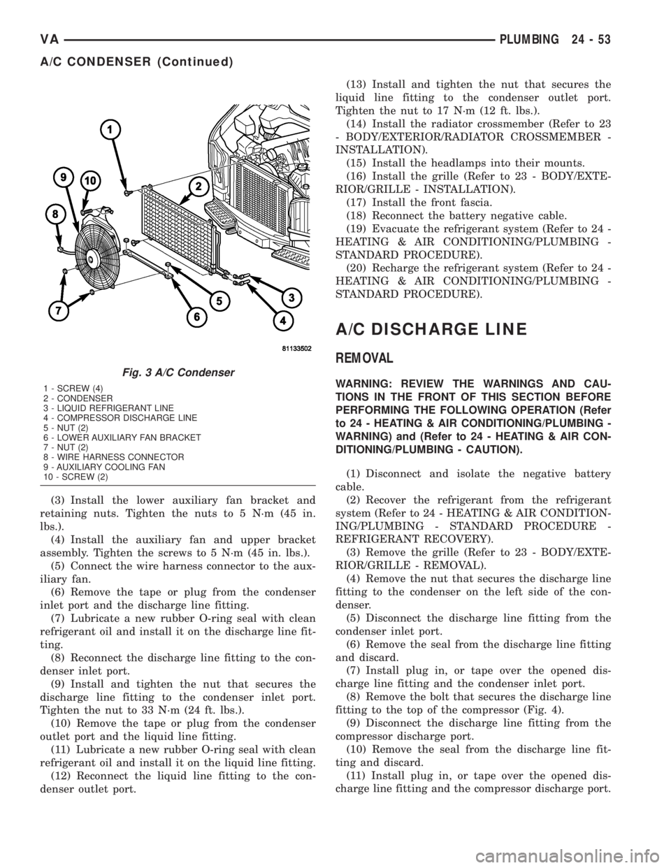
(3) Install the lower auxiliary fan bracket and
retaining nuts. Tighten the nuts to 5 N´m (45 in.
lbs.).
(4) Install the auxiliary fan and upper bracket
assembly. Tighten the screws to 5 N´m (45 in. lbs.).
(5) Connect the wire harness connector to the aux-
iliary fan.
(6) Remove the tape or plug from the condenser
inlet port and the discharge line fitting.
(7) Lubricate a new rubber O-ring seal with clean
refrigerant oil and install it on the discharge line fit-
ting.
(8) Reconnect the discharge line fitting to the con-
denser inlet port.
(9) Install and tighten the nut that secures the
discharge line fitting to the condenser inlet port.
Tighten the nut to 33 N´m (24 ft. lbs.).
(10) Remove the tape or plug from the condenser
outlet port and the liquid line fitting.
(11) Lubricate a new rubber O-ring seal with clean
refrigerant oil and install it on the liquid line fitting.
(12) Reconnect the liquid line fitting to the con-
denser outlet port.(13) Install and tighten the nut that secures the
liquid line fitting to the condenser outlet port.
Tighten the nut to 17 N´m (12 ft. lbs.).
(14) Install the radiator crossmember (Refer to 23
- BODY/EXTERIOR/RADIATOR CROSSMEMBER -
INSTALLATION).
(15) Install the headlamps into their mounts.
(16) Install the grille (Refer to 23 - BODY/EXTE-
RIOR/GRILLE - INSTALLATION).
(17) Install the front fascia.
(18) Reconnect the battery negative cable.
(19) Evacuate the refrigerant system (Refer to 24 -
HEATING & AIR CONDITIONING/PLUMBING -
STANDARD PROCEDURE).
(20) Recharge the refrigerant system (Refer to 24 -
HEATING & AIR CONDITIONING/PLUMBING -
STANDARD PROCEDURE).
A/C DISCHARGE LINE
REMOVAL
WARNING: REVIEW THE WARNINGS AND CAU-
TIONS IN THE FRONT OF THIS SECTION BEFORE
PERFORMING THE FOLLOWING OPERATION (Refer
to 24 - HEATING & AIR CONDITIONING/PLUMBING -
WARNING) and (Refer to 24 - HEATING & AIR CON-
DITIONING/PLUMBING - CAUTION).
(1) Disconnect and isolate the negative battery
cable.
(2) Recover the refrigerant from the refrigerant
system (Refer to 24 - HEATING & AIR CONDITION-
ING/PLUMBING - STANDARD PROCEDURE -
REFRIGERANT RECOVERY).
(3) Remove the grille (Refer to 23 - BODY/EXTE-
RIOR/GRILLE - REMOVAL).
(4) Remove the nut that secures the discharge line
fitting to the condenser on the left side of the con-
denser.
(5) Disconnect the discharge line fitting from the
condenser inlet port.
(6) Remove the seal from the discharge line fitting
and discard.
(7) Install plug in, or tape over the opened dis-
charge line fitting and the condenser inlet port.
(8) Remove the bolt that secures the discharge line
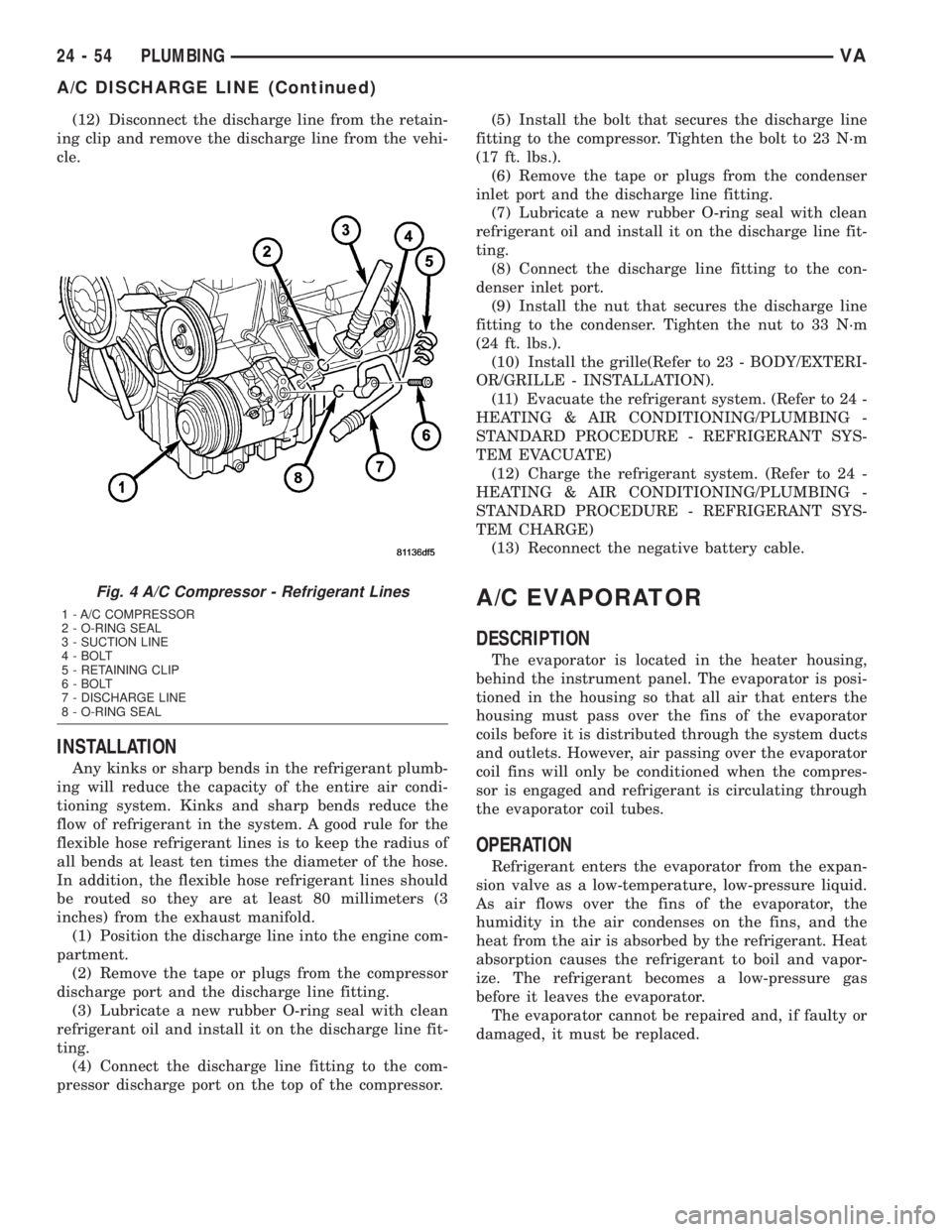
fitting to the top of the compressor (Fig. 4).
(9) Disconnect the discharge line fitting from the
compressor discharge port.
(10) Remove the seal from the discharge line fit-
ting and discard.
(11) Install plug in, or tape over the opened dis-
charge line fitting and the compressor discharge port.
Fig. 3 A/C Condenser
1 - SCREW (4)
2 - CONDENSER
3 - LIQUID REFRIGERANT LINE
4 - COMPRESSOR DISCHARGE LINE
5 - NUT (2)
6 - LOWER AUXILIARY FAN BRACKET
7 - NUT (2)
8 - WIRE HARNESS CONNECTOR
9 - AUXILIARY COOLING FAN
10 - SCREW (2)
VAPLUMBING 24 - 53
A/C CONDENSER (Continued)
Page 1182 of 1232
(12) Disconnect the discharge line from the retain-
ing clip and remove the discharge line from the vehi-
cle.
INSTALLATION
Any kinks or sharp bends in the refrigerant plumb-
ing will reduce the capacity of the entire air condi-
tioning system. Kinks and sharp bends reduce the
flow of refrigerant in the system. A good rule for the
flexible hose refrigerant lines is to keep the radius of
all bends at least ten times the diameter of the hose.
In addition, the flexible hose refrigerant lines should
be routed so they are at least 80 millimeters (3
inches) from the exhaust manifold.
(1) Position the discharge line into the engine com-
partment.
(2) Remove the tape or plugs from the compressor
discharge port and the discharge line fitting.
(3) Lubricate a new rubber O-ring seal with clean
refrigerant oil and install it on the discharge line fit-
ting.
(4) Connect the discharge line fitting to the com-
pressor discharge port on the top of the compressor.(5) Install the bolt that secures the discharge line
fitting to the compressor. Tighten the bolt to 23 N´m
(17 ft. lbs.).
(6) Remove the tape or plugs from the condenser
inlet port and the discharge line fitting.
(7) Lubricate a new rubber O-ring seal with clean
refrigerant oil and install it on the discharge line fit-
ting.
(8) Connect the discharge line fitting to the con-
denser inlet port.
(9) Install the nut that secures the discharge line
fitting to the condenser. Tighten the nut to 33 N´m
(24 ft. lbs.).
(10) Install the grille(Refer to 23 - BODY/EXTERI-
OR/GRILLE - INSTALLATION).
(11) Evacuate the refrigerant system. (Refer to 24 -
HEATING & AIR CONDITIONING/PLUMBING -
STANDARD PROCEDURE - REFRIGERANT SYS-
TEM EVACUATE)
(12) Charge the refrigerant system. (Refer to 24 -
HEATING & AIR CONDITIONING/PLUMBING -
STANDARD PROCEDURE - REFRIGERANT SYS-
TEM CHARGE)
(13) Reconnect the negative battery cable.
A/C EVAPORATOR
DESCRIPTION
The evaporator is located in the heater housing,
behind the instrument panel. The evaporator is posi-
tioned in the housing so that all air that enters the
housing must pass over the fins of the evaporator
coils before it is distributed through the system ducts
and outlets. However, air passing over the evaporator
coil fins will only be conditioned when the compres-
sor is engaged and refrigerant is circulating through
the evaporator coil tubes.
OPERATION
Refrigerant enters the evaporator from the expan-
sion valve as a low-temperature, low-pressure liquid.
As air flows over the fins of the evaporator, the
humidity in the air condenses on the fins, and the
heat from the air is absorbed by the refrigerant. Heat
absorption causes the refrigerant to boil and vapor-
ize. The refrigerant becomes a low-pressure gas
before it leaves the evaporator.
The evaporator cannot be repaired and, if faulty or
damaged, it must be replaced.
Fig. 4 A/C Compressor - Refrigerant Lines
1 - A/C COMPRESSOR
2 - O-RING SEAL
3 - SUCTION LINE
4 - BOLT
5 - RETAINING CLIP
6 - BOLT
7 - DISCHARGE LINE
8 - O-RING SEAL
24 - 54 PLUMBINGVA
A/C DISCHARGE LINE (Continued)
Page 1183 of 1232
REMOVAL
WARNING: ON VEHICLES EQUIPPED WITH AIR-
BAGS, DISABLE THE AIRBAG SYSTEM BEFORE
ATTEMPTING ANY STEERING WHEEL, STEERING
COLUMN, OR INSTRUMENT PANEL COMPONENT
DIAGNOSIS OR SERVICE. DISCONNECT AND ISO-
LATE THE BATTERY NEGATIVE (GROUND) CABLE,
THEN WAIT TWO MINUTES FOR THE AIRBAG SYS-
TEM CAPACITOR TO DISCHARGE BEFORE PER-
FORMING FURTHER DIAGNOSIS OR SERVICE. THIS
IS THE ONLY SURE WAY TO DISABLE THE AIRBAG
SYSTEM. FAILURE TO TAKE THE PROPER PRE-
CAUTIONS COULD RESULT IN AN ACCIDENTAL
AIRBAG DEPLOYMENT AND POSSIBLE PERSONAL
INJURY.
WARNING: REVIEW THE WARNINGS AND CAU-
TIONS IN THE FRONT OF THIS SECTION BEFORE
PERFORMING THE FOLLOWING OPERATION (Refer
to 24 - HEATING & AIR CONDITIONING/PLUMBING -
WARNING) and (Refer to 24 - HEATING & AIR CON-
DITIONING/PLUMBING - CAUTION).
(1) Remove the heater housing (Refer to 24 -
HEATING & AIR CONDITIONING/DISTRIBUTION/
HVAC HOUSING - REMOVAL).
(2) Disassemble the heater housing to access the
evaporator (Refer to 24 - HEATING & AIR CONDI-
TIONING/DISTRIBUTION/HVAC HOUSING - DIS-
ASSEMBLY).
(3) Lift the evaporator out of the lower half of the
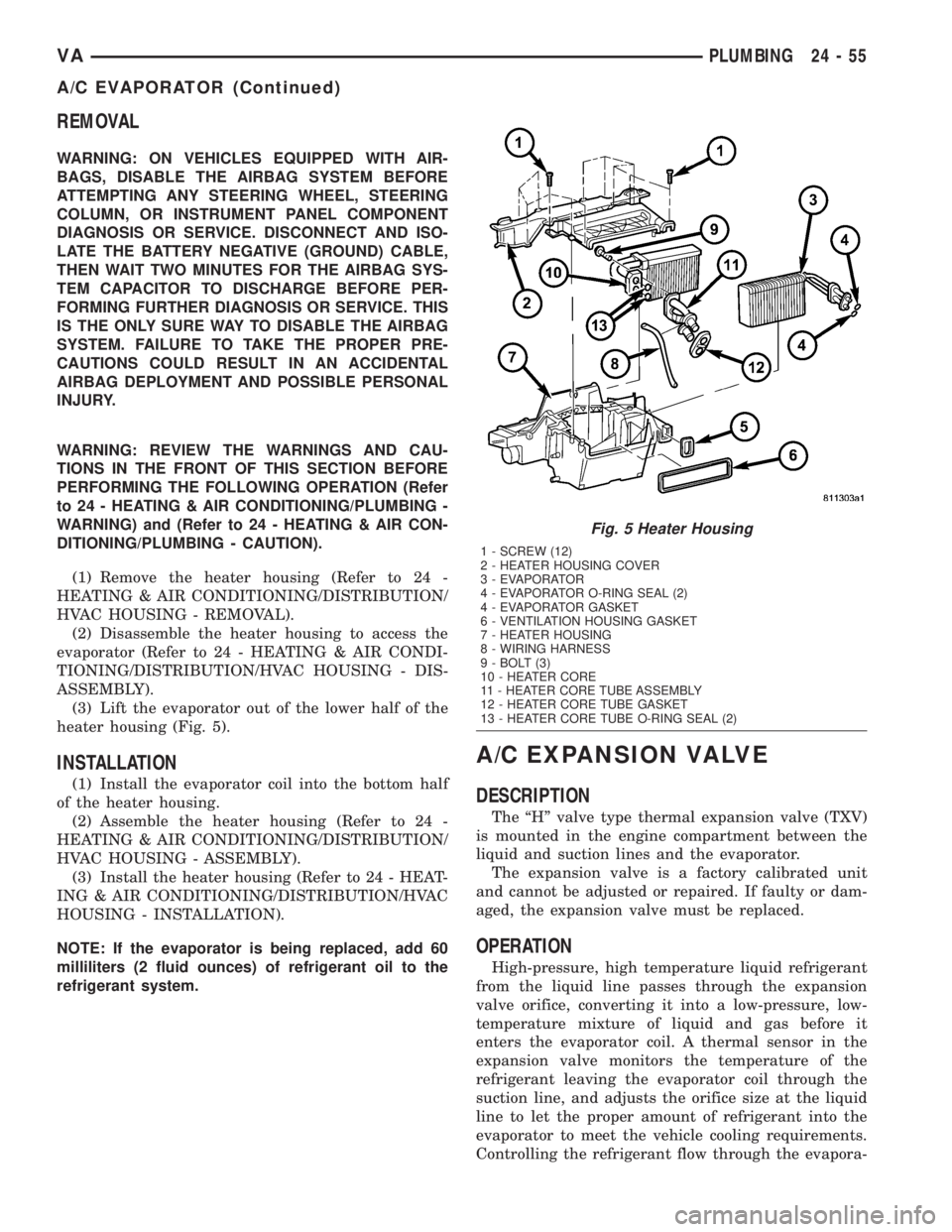
heater housing (Fig. 5).
INSTALLATION
(1) Install the evaporator coil into the bottom half
of the heater housing.
(2) Assemble the heater housing (Refer to 24 -
HEATING & AIR CONDITIONING/DISTRIBUTION/
HVAC HOUSING - ASSEMBLY).
(3) Install the heater housing (Refer to 24 - HEAT-
ING & AIR CONDITIONING/DISTRIBUTION/HVAC
HOUSING - INSTALLATION).
NOTE: If the evaporator is being replaced, add 60
milliliters (2 fluid ounces) of refrigerant oil to the
refrigerant system.
A/C EXPANSION VALVE
DESCRIPTION
The ªHº valve type thermal expansion valve (TXV)
is mounted in the engine compartment between the
liquid and suction lines and the evaporator.
The expansion valve is a factory calibrated unit
and cannot be adjusted or repaired. If faulty or dam-
aged, the expansion valve must be replaced.
OPERATION
High-pressure, high temperature liquid refrigerant
from the liquid line passes through the expansion
valve orifice, converting it into a low-pressure, low-
temperature mixture of liquid and gas before it
enters the evaporator coil. A thermal sensor in the
expansion valve monitors the temperature of the
refrigerant leaving the evaporator coil through the
suction line, and adjusts the orifice size at the liquid
line to let the proper amount of refrigerant into the
evaporator to meet the vehicle cooling requirements.
Controlling the refrigerant flow through the evapora-
Fig. 5 Heater Housing
1 - SCREW (12)
2 - HEATER HOUSING COVER
3 - EVAPORATOR
4 - EVAPORATOR O-RING SEAL (2)
4 - EVAPORATOR GASKET
6 - VENTILATION HOUSING GASKET
7 - HEATER HOUSING
8 - WIRING HARNESS
9 - BOLT (3)
10 - HEATER CORE
11 - HEATER CORE TUBE ASSEMBLY
12 - HEATER CORE TUBE GASKET
13 - HEATER CORE TUBE O-RING SEAL (2)
VAPLUMBING 24 - 55
A/C EVAPORATOR (Continued)
Page 1184 of 1232
tor ensures that none of the refrigerant leaving the
evaporator is still in a liquid state, which could cause
damage to the compressor.
DIAGNOSIS AND TESTING - A/C EXPANSION
VALVE
The expansion valve is located on the engine side
of the dash panel near the shock tower.
The expansion valve can fail in three different
positions (open, closed or restricted).
In an Open Position: this will result in a noisy
compressor or no cooling. The cause can be broken
spring, broken ball or excessive moisture in the A/C
system. If the spring or ball are found to be defective,
replace the expansion valve. If excessive moisture is
found in the A/C system, recycle the refrigerant.
In a Closed Position: There will be low suction
pressure and no cooling. This may be caused by a
failed power dome or excessive moisture in the A/C
system. If the power dome on the expansion valve is
found to be defective replace the expansion valve. If
excessive moisture is found recycle the refrigerant.
A Restricted Orifice: There will be low suction
pressure and no cooling. This may be caused by
debris in the refrigerant system. If debris is believed
to be the cause, recycle the refrigerant and replace
the expansion valve and the receiver-drier.
REMOVAL
WARNING: REFER TO THE APPLICABLE WARN-
INGS AND CAUTIONS FOR THIS SYSTEM BEFORE
PERFORMING THE FOLLOWING OPERATION (Refer
to 24 - HEATING & AIR CONDITIONING/PLUMBING -
WARNING) and (Refer to 24 - HEATING & AIR CON-
DITIONING/PLUMBING - CAUTION).
(1) Recover the refrigerant from the A/C system-
(Refer to 24 - HEATING & AIR CONDITIONING/
PLUMBING - STANDARD PROCEDURE).
(2) Disconnect and isolate the battery negative
cable.
(3) Remove the nut that secures the suction and
liquid line fittings to the stud on the expansion valve
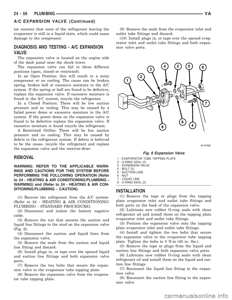
(Fig. 6).
(4) Disconnect the suction and liquid lines from
the expansion valve.
(5) Remove the seals from the suction and liquid
line fitting and discard.
(6) Install plugs in, or tape over the opened liquid
and suction line fittings and both expansion valve
ports.
(7) Remove the two bolts that secure the expan-
sion valve to the evaporator tube tapping plate.
(8) Remove the expansion valve from the evapora-
tor tube tapping plate.(9) Remove the seals from the evaporator inlet and
outlet tube fittings and discard.
(10) Install plugs in, or tape over the opened evap-
orator inlet and outlet tube fittings and both expan-
sion valve ports.
INSTALLATION
(1) Remove the tape or plugs from the tapping
plate evaporator inlet and outlet tube fittings and
both ports on the back of the expansion valve.
(2) Lubricate new rubber O-ring seals with clean
refrigerant oil and install them on the tapping plate
evaporator inlet and outlet tube fittings.
(3) Position the expansion valve onto the tapping
plate evaporator inlet and outlet tube fittings.
(4) Install and tighten the two bolts that secure
the expansion valve to the evaporator tube tapping
plate. Tighten the bolts to 5 N´m (45 in. lbs.).
(5) Remove the tape or plugs from the liquid and
suction line fittings and both expansion valve ports.
(6) Lubricate new rubber O-ring seals with clean
refrigerant oil and install them on the liquid and suc-
tion line fittings.
(7) Reconnect the liquid line fitting to the expan-
sion valve.
(8) Reconnect the suction line fitting to the expan-
sion valve.
Fig. 6 Expansion Valve
1 - EVAPORATOR TUBE TAPPING PLATE
2 - O-RING SEAL (2)
3 - EXPANSION VALVE
4 - BOLT (2)
5 - SUCTION LINE
6 - NUT
7 - LIQUID LINE
8 - O-RING SEAL (2)
24 - 56 PLUMBINGVA
A/C EXPANSION VALVE (Continued)
Page 1185 of 1232
(9) Install and tighten the nut that secures the
suction line and liquid line fittings to the stud on the
expansion valve. Tighten the nut to 10 N´m (89 in.
lbs.).
(10) Reconnect the battery negative cable.
(11) Evacuate the refrigerant system (Refer to 24 -
HEATING & AIR CONDITIONING/PLUMBING -
STANDARD PROCEDURE).
(12) Charge the refrigerant system (Refer to 24 -
HEATING & AIR CONDITIONING/PLUMBING -
STANDARD PROCEDURE).
ELECTRIC COOLANT PUMP
DESCRIPTION
The electric coolant pump is used on all vehicles.
The pump is located in the left side of the engine
compartment near the battery.
OPERATION
The pump is controlled by the ATC control module
and is only operational under the following condi-
tions:
(1) Vehicle speed below 27 Km/h (17 mph).
(2) Coolant temperature above 65É C (150É F) but
less than 110É C (230 É F).
(3) Any blower speed setting.
(4) Temperature heat setting above the halfway
setting (60% heat).
(5) The pump will turn off at speeds above 48
Km/h (30 mph).
(6) The pump will turn off if the coolant tempera-
ture rises above 110É C (230 É F).
REMOVAL
(1) Disconnect and isolate the battery negative
cable.
(2) Partially drain the engine cooling system
(Refer to 7 - COOLING/ENGINE/COOLANT - STAN-
DARD PROCEDURE).
(3) Disconnect the wire harness connector from the
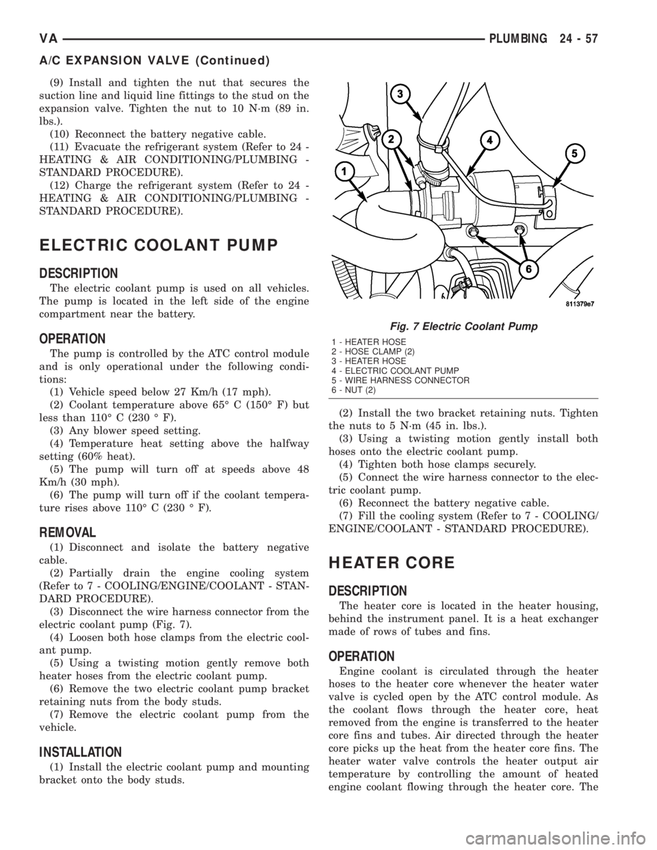
electric coolant pump (Fig. 7).
(4) Loosen both hose clamps from the electric cool-
ant pump.
(5) Using a twisting motion gently remove both
heater hoses from the electric coolant pump.
(6) Remove the two electric coolant pump bracket
retaining nuts from the body studs.
(7) Remove the electric coolant pump from the
vehicle.
INSTALLATION
(1) Install the electric coolant pump and mounting
bracket onto the body studs.(2) Install the two bracket retaining nuts. Tighten
the nuts to 5 N´m (45 in. lbs.).
(3) Using a twisting motion gently install both
hoses onto the electric coolant pump.
(4) Tighten both hose clamps securely.
(5) Connect the wire harness connector to the elec-
tric coolant pump.
(6) Reconnect the battery negative cable.
(7) Fill the cooling system (Refer to 7 - COOLING/
ENGINE/COOLANT - STANDARD PROCEDURE).
HEATER CORE
DESCRIPTION
The heater core is located in the heater housing,
behind the instrument panel. It is a heat exchanger
made of rows of tubes and fins.
OPERATION
Engine coolant is circulated through the heater
hoses to the heater core whenever the heater water
valve is cycled open by the ATC control module. As
the coolant flows through the heater core, heat
removed from the engine is transferred to the heater
core fins and tubes. Air directed through the heater
core picks up the heat from the heater core fins. The
heater water valve controls the heater output air
temperature by controlling the amount of heated
engine coolant flowing through the heater core. The
Fig. 7 Electric Coolant Pump
1 - HEATER HOSE
2 - HOSE CLAMP (2)
3 - HEATER HOSE
4 - ELECTRIC COOLANT PUMP
5 - WIRE HARNESS CONNECTOR
6 - NUT (2)
VAPLUMBING 24 - 57
A/C EXPANSION VALVE (Continued)
Page 1186 of 1232
blower motor speed controls the volume of air flowing
through the heater housing.
The heater core cannot be repaired and, if faulty or
damaged, it must be replaced.
REMOVAL
WARNING: ON VEHICLES EQUIPPED WITH AIR-
BAGS, DISABLE THE AIRBAG SYSTEM BEFORE
ATTEMPTING ANY STEERING WHEEL, STEERING
COLUMN, OR INSTRUMENT PANEL COMPONENT
DIAGNOSIS OR SERVICE. DISCONNECT AND ISO-
LATE THE BATTERY NEGATIVE (GROUND) CABLE,
THEN WAIT TWO MINUTES FOR THE AIRBAG SYS-
TEM CAPACITOR TO DISCHARGE BEFORE PER-
FORMING FURTHER DIAGNOSIS OR SERVICE. THIS
IS THE ONLY SURE WAY TO DISABLE THE AIRBAG
SYSTEM. FAILURE TO TAKE THE PROPER PRE-
CAUTIONS COULD RESULT IN AN ACCIDENTAL
AIRBAG DEPLOYMENT AND POSSIBLE PERSONAL
INJURY.
WARNING: REVIEW THE WARNINGS AND CAU-
TIONS IN THE FRONT OF THIS SECTION BEFORE
PERFORMING THE FOLLOWING OPERATION (Refer
to 24 - HEATING & AIR CONDITIONING/PLUMBING -
WARNING) and (Refer to 24 - HEATING & AIR CON-
DITIONING/PLUMBING - CAUTION).
(1) Remove the heater housing (Refer to 24 -
HEATING & AIR CONDITIONING/DISTRIBUTION/
HVAC HOUSING - REMOVAL).
(2) Disassemble the heater housing to access the
heater core (Refer to 24 - HEATING & AIR CONDI-
TIONING/DISTRIBUTION/HVAC HOUSING - DIS-
ASSEMBLY).
(3) Lift the heater core out of the lower half of the
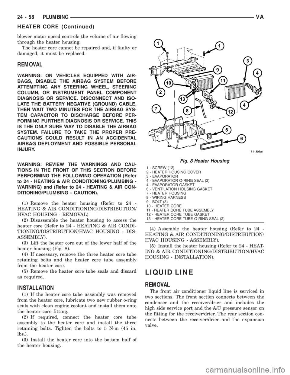
heater housing (Fig. 8).
(4) If necessary, remove the three heater core tube
retaining bolts and the heater core tube assembly
from the heater core.
(5) Remove the heater core tube seals and discard
as required.
INSTALLATION
(1) If the heater core tube assembly was removed
from the heater core, lubricate two new rubber o-ring
seals with clean engine coolant and install them onto
the heater core fitting.
(2) If required, connect the heater core tube
assembly to the heater core and install the three
retaining bolts. Tighten the bolts to 5 N´m (45 in.
lbs.).
(3) Install the heater core into the bottom half of
the heater housing.(4) Assemble the heater housing (Refer to 24 -
HEATING & AIR CONDITIONING/DISTRIBUTION/
HVAC HOUSING - ASSEMBLY).
(5) Install the heater housing (Refer to 24 - HEAT-
ING & AIR CONDITIONING/DISTRIBUTION/HVAC
HOUSING - INSTALLATION).
LIQUID LINE
REMOVAL
The front air conditioner liquid line is serviced in
two sections. The front section connects between the
condenser and the receiver/drier and includes the
high side service port and the A/C pressure sensor on
the fitting for the receiver/drier. The rear section con-
nects between the receiver/drier and the expansion
valve.
Fig. 8 Heater Housing
1 - SCREW (12)
2 - HEATER HOUSING COVER
3 - EVAPORATOR
4 - EVAPORATOR O-RING SEAL (2)
4 - EVAPORATOR GASKET
6 - VENTILATION HOUSING GASKET
7 - HEATER HOUSING
8 - WIRING HARNESS
9 - BOLT (3)
10 - HEATER CORE
11 - HEATER CORE TUBE ASSEMBLY
12 - HEATER CORE TUBE GASKET
13 - HEATER CORE TUBE O-RING SEAL (2)
24 - 58 PLUMBINGVA
HEATER CORE (Continued)
Page 1187 of 1232
WARNING: REVIEW THE WARNINGS AND CAU-
TIONS IN THE FRONT OF THIS SECTION BEFORE
PERFORMING THE FOLLOWING OPERATION (Refer
to 24 - HEATING & AIR CONDITIONING/PLUMBING -
WARNING) and (Refer to 24 - HEATING & AIR CON-
DITIONING/PLUMBING - CAUTION).
FRONT SECTION
(1) Recover the refrigerant from the refrigerant
system (Refer to 24 - HEATING & AIR CONDITION-
ING/PLUMBING - STANDARD PROCEDURE).
(2) Disconnect and isolate the battery negative
cable.
(3) Remove the grille (Refer to 23 - BODY/EXTE-
RIOR/GRILLE - REMOVAL).
(4) Remove the nut that secures the liquid line fit-
ting to the condenser outlet port on the left side of
condenser.
(5) Disconnect the liquid line fitting from the con-
denser outlet port.
(6) Remove the seal from the liquid line fitting and
discard.
(7) Install plug in, or tape over the opened liquid
line fitting and the condenser outlet port.
(8) Remove the routing clip retaining nut and dis-
engage the routing clip retainer on top of the left
frame rail from the front section of the liquid line.
(9) Remove the A/C pressure sensor from the front
liquid line fitting (Refer to 24 - HEATING & AIR
CONDITIONING/CONTROLS/A/C PRESSURE
TRANSDUCER - REMOVAL).
(10) Remove the bolt that secures the front section
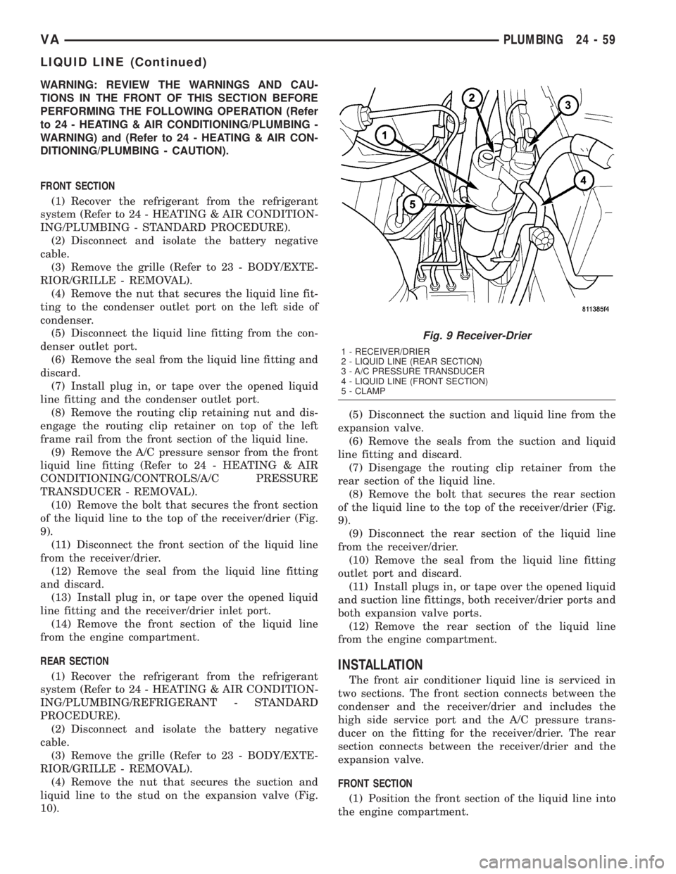
of the liquid line to the top of the receiver/drier (Fig.
9).
(11) Disconnect the front section of the liquid line
from the receiver/drier.
(12) Remove the seal from the liquid line fitting
and discard.
(13) Install plug in, or tape over the opened liquid
line fitting and the receiver/drier inlet port.
(14) Remove the front section of the liquid line
from the engine compartment.
REAR SECTION
(1) Recover the refrigerant from the refrigerant
system (Refer to 24 - HEATING & AIR CONDITION-
ING/PLUMBING/REFRIGERANT - STANDARD
PROCEDURE).
(2) Disconnect and isolate the battery negative
cable.
(3) Remove the grille (Refer to 23 - BODY/EXTE-
RIOR/GRILLE - REMOVAL).
(4) Remove the nut that secures the suction and
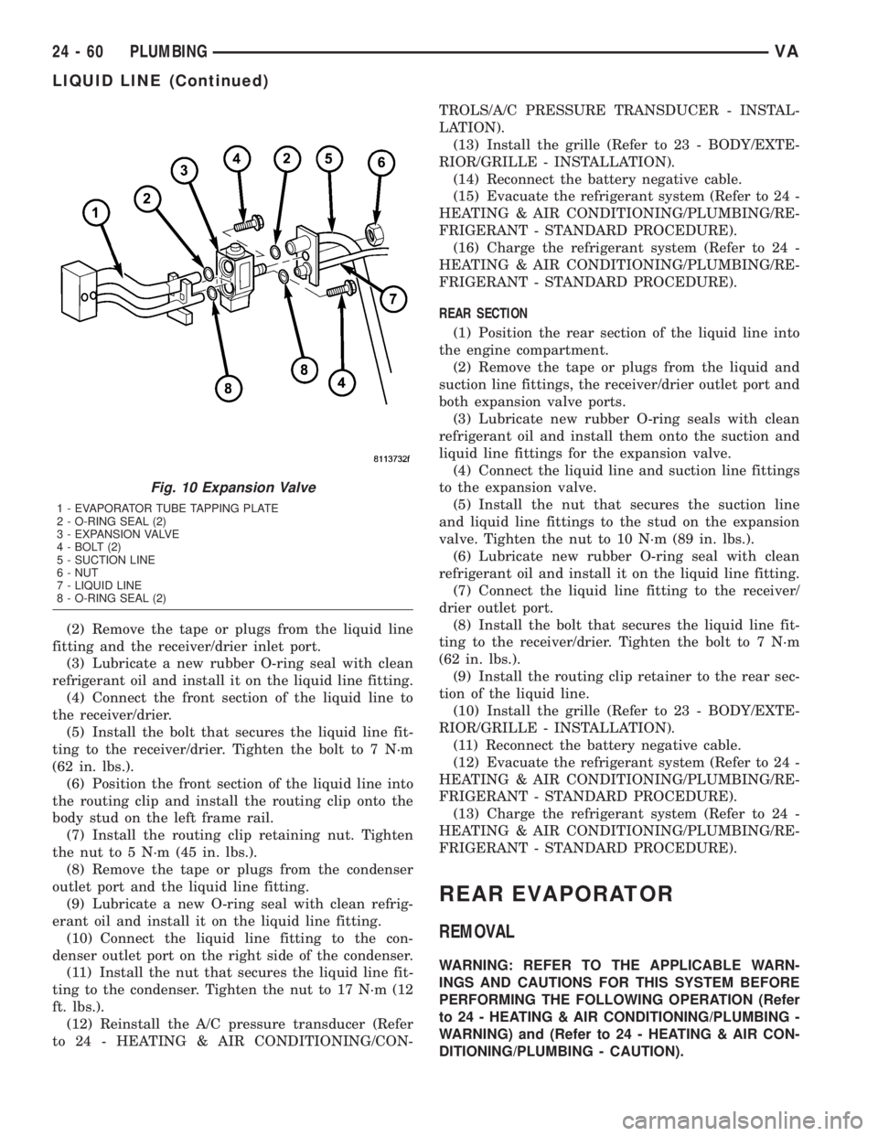
liquid line to the stud on the expansion valve (Fig.
10).(5) Disconnect the suction and liquid line from the
expansion valve.
(6) Remove the seals from the suction and liquid
line fitting and discard.
(7) Disengage the routing clip retainer from the
rear section of the liquid line.
(8) Remove the bolt that secures the rear section
of the liquid line to the top of the receiver/drier (Fig.
9).
(9) Disconnect the rear section of the liquid line
from the receiver/drier.
(10) Remove the seal from the liquid line fitting
outlet port and discard.
(11) Install plugs in, or tape over the opened liquid
and suction line fittings, both receiver/drier ports and
both expansion valve ports.
(12) Remove the rear section of the liquid line
from the engine compartment.
INSTALLATION
The front air conditioner liquid line is serviced in
two sections. The front section connects between the
condenser and the receiver/drier and includes the
high side service port and the A/C pressure trans-
ducer on the fitting for the receiver/drier. The rear
section connects between the receiver/drier and the
expansion valve.
FRONT SECTION
(1) Position the front section of the liquid line into
the engine compartment.
Fig. 9 Receiver-Drier
1 - RECEIVER/DRIER
2 - LIQUID LINE (REAR SECTION)
3 - A/C PRESSURE TRANSDUCER
4 - LIQUID LINE (FRONT SECTION)
5 - CLAMP
VAPLUMBING 24 - 59
LIQUID LINE (Continued)
Page 1188 of 1232
(2) Remove the tape or plugs from the liquid line
fitting and the receiver/drier inlet port.
(3) Lubricate a new rubber O-ring seal with clean
refrigerant oil and install it on the liquid line fitting.
(4) Connect the front section of the liquid line to
the receiver/drier.
(5) Install the bolt that secures the liquid line fit-
ting to the receiver/drier. Tighten the bolt to 7 N´m
(62 in. lbs.).
(6) Position the front section of the liquid line into
the routing clip and install the routing clip onto the
body stud on the left frame rail.
(7) Install the routing clip retaining nut. Tighten
the nut to 5 N´m (45 in. lbs.).
(8) Remove the tape or plugs from the condenser
outlet port and the liquid line fitting.
(9) Lubricate a new O-ring seal with clean refrig-
erant oil and install it on the liquid line fitting.
(10) Connect the liquid line fitting to the con-
denser outlet port on the right side of the condenser.
(11) Install the nut that secures the liquid line fit-
ting to the condenser. Tighten the nut to 17 N´m (12
ft. lbs.).
(12) Reinstall the A/C pressure transducer (Refer
to 24 - HEATING & AIR CONDITIONING/CON-TROLS/A/C PRESSURE TRANSDUCER - INSTAL-
LATION).
(13) Install the grille (Refer to 23 - BODY/EXTE-
RIOR/GRILLE - INSTALLATION).
(14) Reconnect the battery negative cable.
(15) Evacuate the refrigerant system (Refer to 24 -
HEATING & AIR CONDITIONING/PLUMBING/RE-
FRIGERANT - STANDARD PROCEDURE).
(16) Charge the refrigerant system (Refer to 24 -
HEATING & AIR CONDITIONING/PLUMBING/RE-
FRIGERANT - STANDARD PROCEDURE).
REAR SECTION
(1) Position the rear section of the liquid line into
the engine compartment.
(2) Remove the tape or plugs from the liquid and
suction line fittings, the receiver/drier outlet port and
both expansion valve ports.
(3) Lubricate new rubber O-ring seals with clean
refrigerant oil and install them onto the suction and
liquid line fittings for the expansion valve.
(4) Connect the liquid line and suction line fittings
to the expansion valve.
(5) Install the nut that secures the suction line
and liquid line fittings to the stud on the expansion
valve. Tighten the nut to 10 N´m (89 in. lbs.).
(6) Lubricate new rubber O-ring seal with clean
refrigerant oil and install it on the liquid line fitting.
(7) Connect the liquid line fitting to the receiver/
drier outlet port.
(8) Install the bolt that secures the liquid line fit-
ting to the receiver/drier. Tighten the bolt to 7 N´m
(62 in. lbs.).
(9) Install the routing clip retainer to the rear sec-
tion of the liquid line.
(10) Install the grille (Refer to 23 - BODY/EXTE-
RIOR/GRILLE - INSTALLATION).
(11) Reconnect the battery negative cable.
(12) Evacuate the refrigerant system (Refer to 24 -
HEATING & AIR CONDITIONING/PLUMBING/RE-
FRIGERANT - STANDARD PROCEDURE).
(13) Charge the refrigerant system (Refer to 24 -
HEATING & AIR CONDITIONING/PLUMBING/RE-
FRIGERANT - STANDARD PROCEDURE).
REAR EVAPORATOR
REMOVAL
WARNING: REFER TO THE APPLICABLE WARN-
INGS AND CAUTIONS FOR THIS SYSTEM BEFORE
PERFORMING THE FOLLOWING OPERATION (Refer
to 24 - HEATING & AIR CONDITIONING/PLUMBING -
WARNING) and (Refer to 24 - HEATING & AIR CON-
DITIONING/PLUMBING - CAUTION).
Fig. 10 Expansion Valve
1 - EVAPORATOR TUBE TAPPING PLATE
2 - O-RING SEAL (2)
3 - EXPANSION VALVE
4 - BOLT (2)
5 - SUCTION LINE
6 - NUT
7 - LIQUID LINE
8 - O-RING SEAL (2)
24 - 60 PLUMBINGVA
LIQUID LINE (Continued)
Page 1189 of 1232
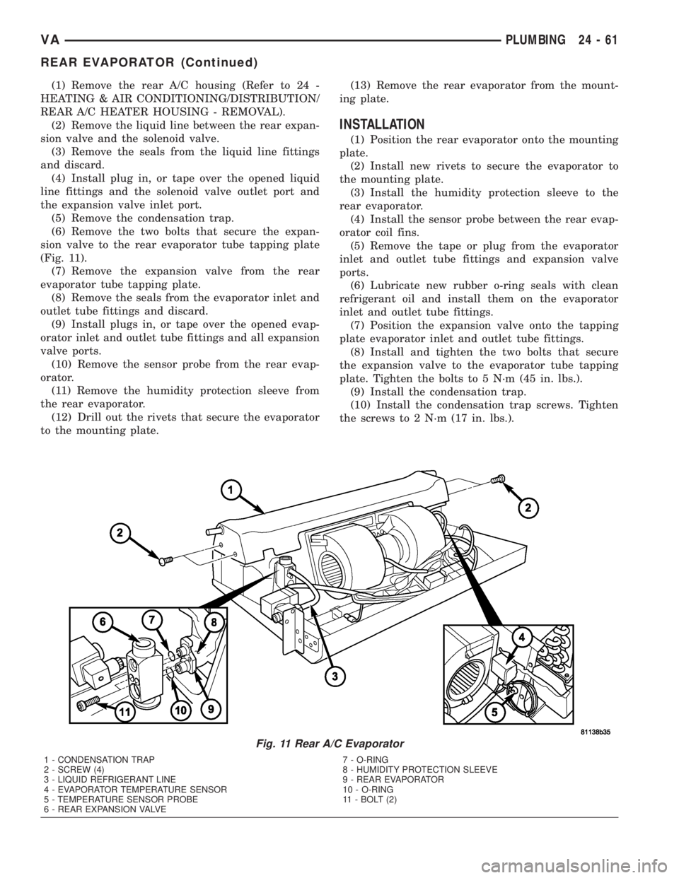
(1) Remove the rear A/C housing (Refer to 24 -
HEATING & AIR CONDITIONING/DISTRIBUTION/
REAR A/C HEATER HOUSING - REMOVAL).
(2) Remove the liquid line between the rear expan-
sion valve and the solenoid valve.
(3) Remove the seals from the liquid line fittings
and discard.
(4) Install plug in, or tape over the opened liquid
line fittings and the solenoid valve outlet port and
the expansion valve inlet port.
(5) Remove the condensation trap.
(6) Remove the two bolts that secure the expan-
sion valve to the rear evaporator tube tapping plate
(Fig. 11).
(7) Remove the expansion valve from the rear
evaporator tube tapping plate.
(8) Remove the seals from the evaporator inlet and
outlet tube fittings and discard.
(9) Install plugs in, or tape over the opened evap-
orator inlet and outlet tube fittings and all expansion
valve ports.
(10) Remove the sensor probe from the rear evap-
orator.
(11) Remove the humidity protection sleeve from
the rear evaporator.
(12) Drill out the rivets that secure the evaporator
to the mounting plate.(13) Remove the rear evaporator from the mount-
ing plate.
INSTALLATION
(1) Position the rear evaporator onto the mounting
plate.
(2) Install new rivets to secure the evaporator to
the mounting plate.
(3) Install the humidity protection sleeve to the
rear evaporator.
(4) Install the sensor probe between the rear evap-
orator coil fins.
(5) Remove the tape or plug from the evaporator
inlet and outlet tube fittings and expansion valve
ports.
(6) Lubricate new rubber o-ring seals with clean
refrigerant oil and install them on the evaporator
inlet and outlet tube fittings.
(7) Position the expansion valve onto the tapping
plate evaporator inlet and outlet tube fittings.
(8) Install and tighten the two bolts that secure
the expansion valve to the evaporator tube tapping
plate. Tighten the bolts to 5 N´m (45 in. lbs.).
(9) Install the condensation trap.
(10) Install the condensation trap screws. Tighten
the screws to 2 N´m (17 in. lbs.).
Fig. 11 Rear A/C Evaporator
1 - CONDENSATION TRAP
2 - SCREW (4)
3 - LIQUID REFRIGERANT LINE
4 - EVAPORATOR TEMPERATURE SENSOR
5 - TEMPERATURE SENSOR PROBE
6 - REAR EXPANSION VALVE7 - O-RING
8 - HUMIDITY PROTECTION SLEEVE
9 - REAR EVAPORATOR
10 - O-RING
11 - BOLT (2)
VAPLUMBING 24 - 61
REAR EVAPORATOR (Continued)
Page 1190 of 1232
(11) Remove the tape or plug from the liquid line
fittings and the solenoid valve outlet port and the
expansion valve inlet port.
(12) Lubricate new rubber o-ring seals with clean
refrigerant oil and install them on the liquid line fit-
tings.
(13) Install the liquid line between the rear expan-
sion valve and the solenoid valve.
(14) Install and tighten the nuts that secures the
liquid line fittings to the rear expansion valve and
solenoid valve. Tighten the nuts to 16 N´m (142 in.
lbs.).
(15) Install the rear A/C housing (Refer to 24 -
HEATING & AIR CONDITIONING/DISTRIBUTION/
REAR A/C HEATER HOUSING - INSTALLATION).
NOTE: If the evaporator is being replaced, add 30
milliliters (1 fluid ounce) of refrigerant oil to the
refrigerant system.
REAR EXPANSION VALVE
REMOVAL
WARNING: REFER TO THE APPLICABLE WARN-
INGS AND CAUTIONS FOR THIS SYSTEM BEFORE
PERFORMING THE FOLLOWING OPERATION (Refer
to 24 - HEATING & AIR CONDITIONING/PLUMBING -
WARNING) and (Refer to 24 - HEATING & AIR CON-
DITIONING/PLUMBING - CAUTION).
(1) Recover the refrigerant from the A/C system
(Refer to 24 - HEATING & AIR CONDITIONING/
PLUMBING - STANDARD PROCEDURE).
(2) Disconnect and isolate the battery negative
cable.
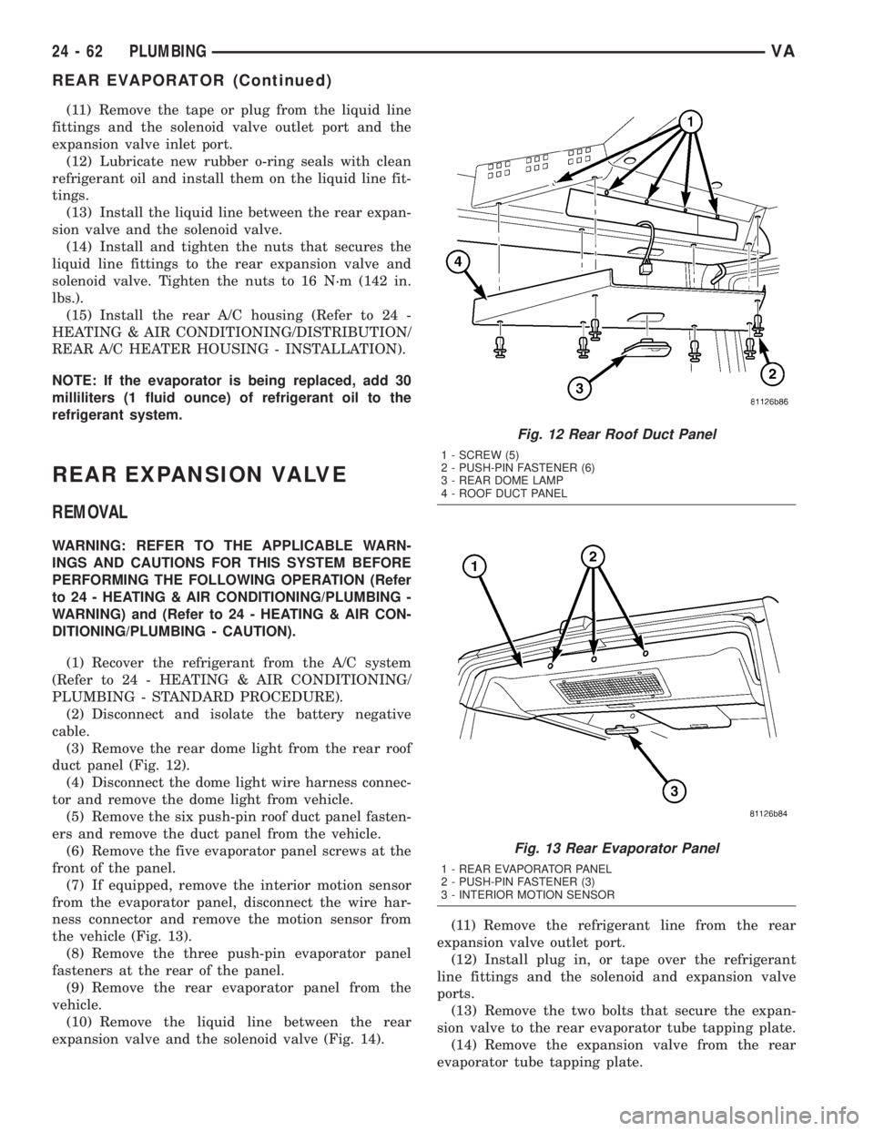
(3) Remove the rear dome light from the rear roof
duct panel (Fig. 12).
(4) Disconnect the dome light wire harness connec-
tor and remove the dome light from vehicle.
(5) Remove the six push-pin roof duct panel fasten-
ers and remove the duct panel from the vehicle.
(6) Remove the five evaporator panel screws at the
front of the panel.
(7) If equipped, remove the interior motion sensor
from the evaporator panel, disconnect the wire har-
ness connector and remove the motion sensor from
the vehicle (Fig. 13).
(8) Remove the three push-pin evaporator panel
fasteners at the rear of the panel.
(9) Remove the rear evaporator panel from the
vehicle.
(10) Remove the liquid line between the rear
expansion valve and the solenoid valve (Fig. 14).(11) Remove the refrigerant line from the rear
expansion valve outlet port.
(12) Install plug in, or tape over the refrigerant
line fittings and the solenoid and expansion valve
ports.
(13) Remove the two bolts that secure the expan-
sion valve to the rear evaporator tube tapping plate.
(14) Remove the expansion valve from the rear
evaporator tube tapping plate.
Fig. 12 Rear Roof Duct Panel
1 - SCREW (5)
2 - PUSH-PIN FASTENER (6)
3 - REAR DOME LAMP
4 - ROOF DUCT PANEL
Fig. 13 Rear Evaporator Panel
1 - REAR EVAPORATOR PANEL
2 - PUSH-PIN FASTENER (3)
3 - INTERIOR MOTION SENSOR
24 - 62 PLUMBINGVA
REAR EVAPORATOR (Continued)