MERCEDES-BENZ SPRINTER 2005 Service Repair Manual
Manufacturer: MERCEDES-BENZ, Model Year: 2005, Model line: SPRINTER, Model: MERCEDES-BENZ SPRINTER 2005Pages: 1232, PDF Size: 39.23 MB
Page 201 of 1232
²Trailer Tow Connector- Vehicles equipped
with a factory-approved, field-installed trailer towing
electrical package have a heavy duty 7-way trailer
tow connector installed in a bracket on the trailer
hitch receiver. This package includes a 7-way to
4-way connector adapter unit.
²Trailer Tow Control Module- Vehicles
equipped with a factory-approved, field-installed
trailer towing electrical package have a trailer tow
brake/turn control module located within the driver
side front seat riser that controls the brake lamp and
turn signal lamp outputs to the trailer lighting cir-
cuits.
²Turn Signal Relay- A turn signal relay is
installed in the fuse block located on the underside of
the steering column behind a fuse access panel in the
steering column opening cover on the instrument
panel. The electronic circuitry of the wipers, turn sig-
nals and engine start control module within the fuse
block controls the turn signal relay.
²Wipers, Turn Signals, Engine Start Control
Module- The wipers, turn signals and engine start
control module is integral to the fuse block located on
the underside of the steering column behind a fuse
access panel in the steering column opening cover on
the instrument panel. This module includes active
electronic elements that control the operation of the
turn signal relay based upon inputs from the multi-
function switch and feedback from the turn signal
circuits. (Refer to 8 - ELECTRICAL/POWER DISTRI-
BUTION/FUSE BLOCK - DESCRIPTION).
Hard wired circuitry connects the exterior lighting
system components to the electrical system of the
vehicle. These hard wired circuits are integral to sev-
eral wire harnesses, which are routed throughout the
vehicle and retained by many different methods.
These circuits may be connected to each other, to the
vehicle electrical system and to the exterior lighting
system components through the use of a combination
of soldered splices, splice block connectors, and many
different types of wire harness terminal connectors
and insulators. Refer to the appropriate wiring infor-
mation. The wiring information includes wiring dia-
grams, proper wire and connector repair procedures,
further details on wire harness routing and reten-
tion, as well as pin-out and location views for the
various wire harness connectors, splices and grounds.
OPERATION
Following are paragraphs that briefly describe the
operation of each of the major exterior lighting sys-
tems. The hard wired circuits and components of the
exterior lighting systems may be diagnosed and
tested using conventional diagnostic tools and proce-
dures. However, conventional diagnostic methods
may not prove conclusive in the diagnosis of the wip-ers, turn signals and engine start control module
located within the fuse block underneath the steering
column, the ElectroMechanical Instrument Cluster
(EMIC), the Engine Control Module (ECM), or the
Controller Area Network (CAN) data bus network.
The most reliable, efficient, and accurate means to
diagnose the electronic module within the fuse block,
the EMIC, the ECM, and the CAN data bus network
inputs and outputs related to the various exterior
lighting systems requires the use of a DRBIIItscan
tool. Refer to the appropriate diagnostic information.
BACKUP LAMPS
The backup (or reverse) lamps have a path to
ground received at all times through the vehicle wire
harness from a ground point located on the frame
near the left end of the tailgate sill. The backup
lamps receive battery current on the backup lamp
supply circuit only when the backup lamp switch cir-
cuit of the Transmission Range Sensor (TRS) integral
to the gear shifter assembly is closed by the gear
shifter mechanism.
BRAKE LAMPS
The brake (or stop) lamps have a path to ground at
all times through the vehicle wire harness from a
ground point located on the frame near the left end
of the tailgate sill. The Center High Mounted Stop
Lamp (CHMSL) has a path to ground at all times
through the vehicle wire harness from a ground point
on the left side of the dash panel. The brake lamps
and CHMSL receive battery current on the brake
lamp switch output circuit when the brake lamp
switch is closed by the brake pedal arm.
DAYTIME RUNNING LAMPS
Vehicles manufactured for sale in Canada illumi-
nate the low beam headlamp bulb when the engine is
running and the exterior lamps are turned off. This
feature is enabled by the right and left Daytime Run-
ning Lamps (DRL) relays. When the DRL relays are
de-energized, they provide fused battery current from
the circuit K26 relay to the headlamp low beams.
When the headlamps are turned On using the left
(lighting) control stalk of the multi-function switch
the DRL relays are energized, which returns control
of the headlamps to the headlamp switch circuitry of
the multi-function switch. The circuit K26 relay is
energized by the Electro-Mechanical Instrument
Cluster (EMIC) whenever it receives an electronic
message from the Engine Control Module (ECM) over
the Controller Area Network (CAN) data bus indicat-
ing that the engine is running. The DRL and circuit
K26 relays are installed in a relay bracket located
below the forward edge of the driver side front seat
cushion within the driver side front seat riser.
VALAMPS/LIGHTING - EXTERIOR 8L - 3
LAMPS/LIGHTING - EXTERIOR (Continued)
Page 202 of 1232
FRONT FOG LAMPS
Vehicles equipped with optional front fog lamps
have a front fog lamp relay installed in a relay
bracket located below the forward edge of the driver
side front seat cushion within the driver side front
seat riser, a fog lamp switch installed in the cluster
bezel on the instrument panel outboard of the steer-
ing column, and a fog lamp bulb installed in each of
the two front lamp units. The front fog lamps have a
path to ground at all times through their connection
to the vehicle wire harness. The headlamp switch cir-
cuitry of the left (lighting) control stalk of the multi-
function switch controls front fog lamp operation by
providing battery current to the front fog lamp relay
only when the low beam headlamps are selected. The
fog lamp switch controls front fog lamp operation by
energizing or de-energizing the front fog lamp relay
control coil.
HAZARD WARNING LAMPS
With the hazard switch in the On position, the
hazard switch button illuminates and the right and
left turn signal indicators as well as the right and
left turn signal lamps begin to flash on and off. When
the hazard warning system is activated, the hazard
switch circuitry within the multi-function switch and
the wipers, turn signals and engine start control
module electronic circuitry within the fuse block will
repeatedly energize and de-energize the turn signal
relay located in the fuse block. The turn signal relay
switches battery current from a fused B(+) fuse in
the fuse block to the turn signal indicators and the
turn signal lamps. The flashing of the hazard switch
button illumination lamp is also controlled by the
output from the turn signal relay.
HEADLAMPS
The headlamp system includes the exterior lighting
switches integral to the left (lighting) control stalk of
the multi-function switch as well as the low and high
beam bulbs installed in the right and left front lamp
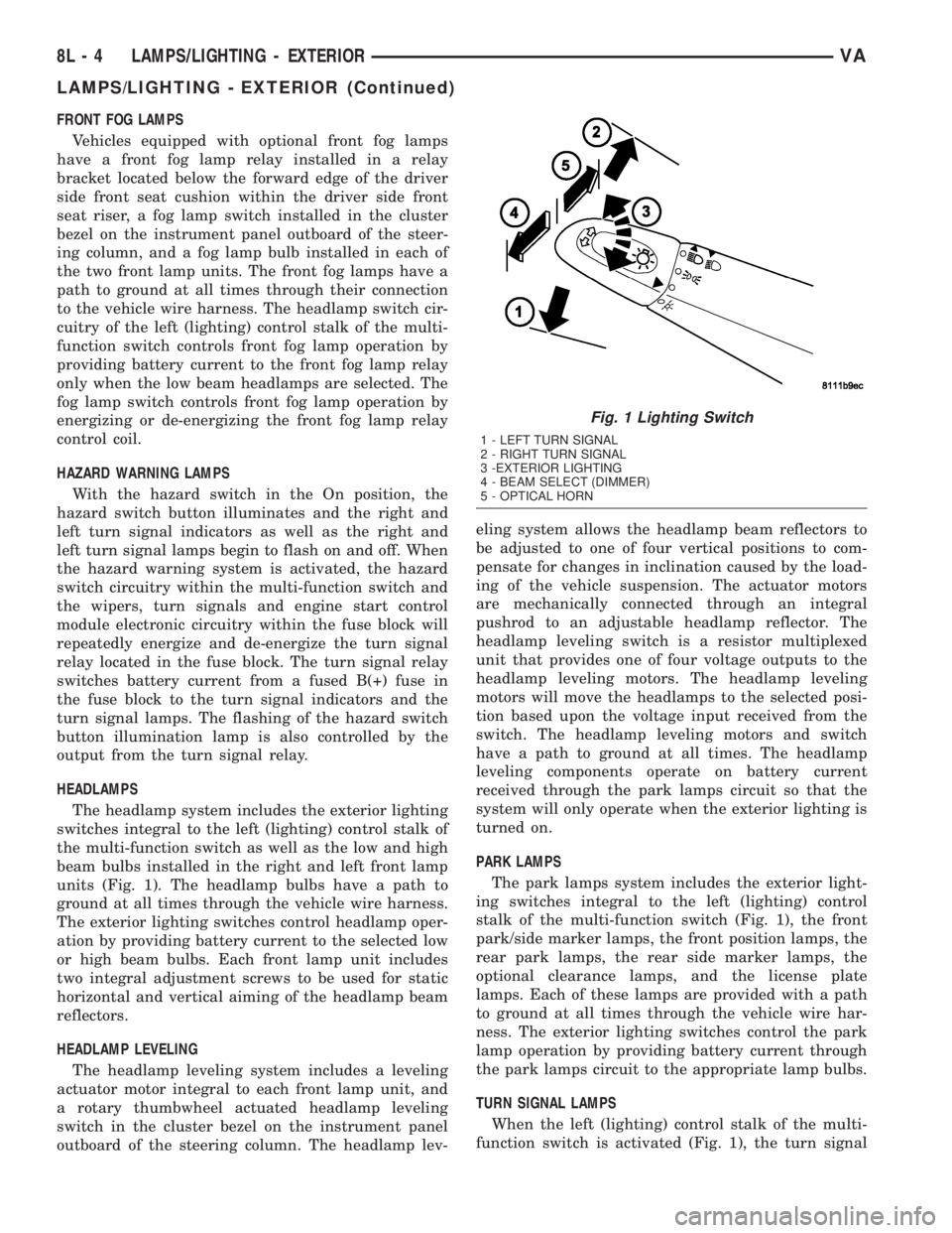
units (Fig. 1). The headlamp bulbs have a path to
ground at all times through the vehicle wire harness.
The exterior lighting switches control headlamp oper-
ation by providing battery current to the selected low
or high beam bulbs. Each front lamp unit includes
two integral adjustment screws to be used for static
horizontal and vertical aiming of the headlamp beam
reflectors.
HEADLAMP LEVELING
The headlamp leveling system includes a leveling
actuator motor integral to each front lamp unit, and
a rotary thumbwheel actuated headlamp leveling
switch in the cluster bezel on the instrument panel
outboard of the steering column. The headlamp lev-eling system allows the headlamp beam reflectors to
be adjusted to one of four vertical positions to com-
pensate for changes in inclination caused by the load-
ing of the vehicle suspension. The actuator motors
are mechanically connected through an integral
pushrod to an adjustable headlamp reflector. The
headlamp leveling switch is a resistor multiplexed
unit that provides one of four voltage outputs to the
headlamp leveling motors. The headlamp leveling
motors will move the headlamps to the selected posi-
tion based upon the voltage input received from the
switch. The headlamp leveling motors and switch
have a path to ground at all times. The headlamp
leveling components operate on battery current
received through the park lamps circuit so that the
system will only operate when the exterior lighting is
turned on.
PARK LAMPS
The park lamps system includes the exterior light-
ing switches integral to the left (lighting) control
stalk of the multi-function switch (Fig. 1), the front
park/side marker lamps, the front position lamps, the
rear park lamps, the rear side marker lamps, the
optional clearance lamps, and the license plate
lamps. Each of these lamps are provided with a path
to ground at all times through the vehicle wire har-
ness. The exterior lighting switches control the park
lamp operation by providing battery current through
the park lamps circuit to the appropriate lamp bulbs.
TURN SIGNAL LAMPS
When the left (lighting) control stalk of the multi-
function switch is activated (Fig. 1), the turn signal
Fig. 1 Lighting Switch
1 - LEFT TURN SIGNAL
2 - RIGHT TURN SIGNAL
3 -EXTERIOR LIGHTING
4 - BEAM SELECT (DIMMER)
5 - OPTICAL HORN
8L - 4 LAMPS/LIGHTING - EXTERIORVA
LAMPS/LIGHTING - EXTERIOR (Continued)
Page 203 of 1232
system illuminates the selected right or left turn sig-
nal indicator and the turn signal lamps begin to
flash. The turn signal lamps include a bulb integral
to each front lamp unit and each tail lamp unit, as
well as a repeater lamp bulb located on each front
fender above the front wheels. When the turn signal
system is activated, the turn signal switch circuitry
within the multi-function switch and the electronic
circuitry of the wipers, turn signals and engine start
control module within the fuse block will repeatedly
energize and de-energize the turn signal relay
located in the fuse block. The turn signal relay
switches battery current from a fused ignition switch
output fuse in the fuse block to the appropriate turn
signal indicator and turn signal lamps.
The ElectroMechanical Instrument Cluster (EMIC)
contactless relay will generate repetitive, audible
turn signal ªclickº sounds to emulate the sounds of a
conventional electro-mechanical turn signal flasher
at one of two rates to coincide with the flashing of
the turn signals. The slow rate emulates normal turn
signal operation, while the fast rate emulates ªbulb
outº turn signal operation.
SPECIFICATIONS - LAMPS/LIGHTING -
EXTERIOR
BULB SPECIFICATIONS
LAMP BULB
Backup P21W - 12V 21W
Brake & Rear Park P21/5W - 12V 21/5W
Center High Mounted
StopP21W - 12V 21W
Clearance W3W - 12V 3W
Front Fog H1 - 12V 55W
Front Position W5W - 12V 5W
Front Turn, Park & Side
Marker3457 NA - 12V 28/7.5W
Amber Glass
Low Beam Headlamp H7 - 12V 55W
High Beam Headlamp H1 - 12V 55W
License Plate C5W - 12V 5W
Rear Side Marker R5W - 12V 5W
Rear Turn P21W - 12V 21W
Side Repeater W5W - 12V 3W
BACKUP LAMP BULB
REMOVAL
(1) Disconnect and isolate the battery negative
cable.(2) If the vehicle is so equipped, remove the trim
from the inside of the right or left rear corner pillar.
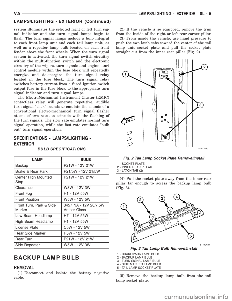
(3) From inside the vehicle, use hand pressure to
push the two latch tabs toward the center of the tail
lamp unit socket plate and pull the socket plate
straight out from the inner rear pillar (Fig. 2).
(4) Pull the socket plate away from the inner rear
pillar far enough to access the backup lamp bulb
(Fig. 3).
(5) Remove the backup lamp bulb from the tail
lamp socket plate.
Fig. 2 Tail Lamp Socket Plate Remove/Install
1 - SOCKET PLATE
2 - INNER REAR PILLAR
3 - LATCH TAB (2)
Fig. 3 Tail Lamp Bulb Remove/Install
1 - BRAKE/PARK LAMP BULB
2 - BACKUP LAMP BULB
3 - TURN SIGNAL LAMP BULB
4 - SIDE MARKER LAMP BULB
5 - TAIL LAMP SOCKET PLATE
VALAMPS/LIGHTING - EXTERIOR 8L - 5
LAMPS/LIGHTING - EXTERIOR (Continued)
Page 204 of 1232
INSTALLATION
(1) Install the backup lamp bulb into the tail lamp
socket plate (Fig. 3).
(2) Align the socket plate with the mounting hole
in the inner rear pillar.
(3) Using hand pressure, push the socket plate
gently and evenly into the inner rear pillar mounting
hole until both latch tabs are fully engaged (Fig. 2).
(4) If the vehicle is so equipped, reinstall the trim
onto the inside of the right or left rear corner pillar.
(5) Reconnect the battery negative cable.
BRAKE LAMP SWITCH
REMOVAL
(1) Disconnect and isolate the battery negative
cable.
(2) Locate the brake lamp switch on the pedal
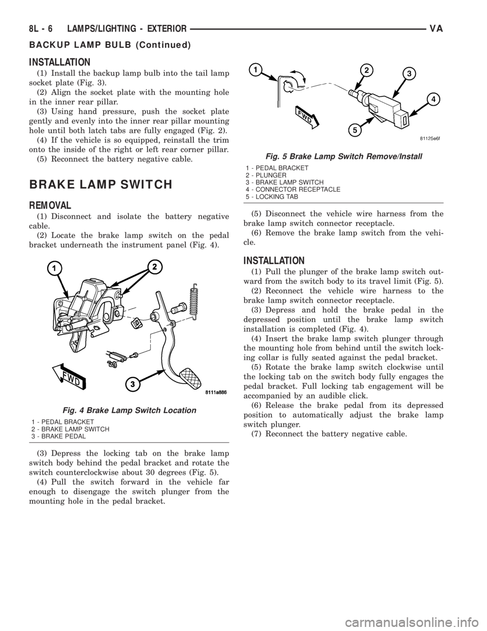
bracket underneath the instrument panel (Fig. 4).
(3) Depress the locking tab on the brake lamp
switch body behind the pedal bracket and rotate the
switch counterclockwise about 30 degrees (Fig. 5).
(4) Pull the switch forward in the vehicle far
enough to disengage the switch plunger from the
mounting hole in the pedal bracket.(5) Disconnect the vehicle wire harness from the
brake lamp switch connector receptacle.
(6) Remove the brake lamp switch from the vehi-
cle.
INSTALLATION
(1) Pull the plunger of the brake lamp switch out-
ward from the switch body to its travel limit (Fig. 5).
(2) Reconnect the vehicle wire harness to the
brake lamp switch connector receptacle.
(3) Depress and hold the brake pedal in the
depressed position until the brake lamp switch
installation is completed (Fig. 4).
(4) Insert the brake lamp switch plunger through
the mounting hole from behind until the switch lock-
ing collar is fully seated against the pedal bracket.
(5) Rotate the brake lamp switch clockwise until
the locking tab on the switch body fully engages the
pedal bracket. Full locking tab engagement will be
accompanied by an audible click.
(6) Release the brake pedal from its depressed
position to automatically adjust the brake lamp
switch plunger.
(7) Reconnect the battery negative cable.
Fig. 4 Brake Lamp Switch Location
1 - PEDAL BRACKET
2 - BRAKE LAMP SWITCH
3 - BRAKE PEDAL
Fig. 5 Brake Lamp Switch Remove/Install
1 - PEDAL BRACKET
2 - PLUNGER
3 - BRAKE LAMP SWITCH
4 - CONNECTOR RECEPTACLE
5 - LOCKING TAB
8L - 6 LAMPS/LIGHTING - EXTERIORVA
BACKUP LAMP BULB (Continued)
Page 205 of 1232
BRAKE/PARK LAMP BULB
REMOVAL
(1) Disconnect and isolate the battery negative
cable.
(2) If the vehicle is so equipped, remove the trim
from the inside of the right or left rear corner pillar.
(3) From inside the vehicle, use hand pressure to
push the two latch tabs toward the center of the tail
lamp unit socket plate and pull the socket plate
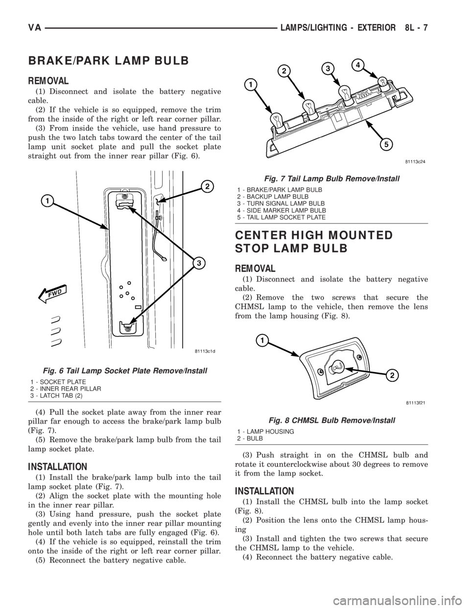
straight out from the inner rear pillar (Fig. 6).
(4) Pull the socket plate away from the inner rear
pillar far enough to access the brake/park lamp bulb
(Fig. 7).
(5) Remove the brake/park lamp bulb from the tail
lamp socket plate.
INSTALLATION
(1) Install the brake/park lamp bulb into the tail
lamp socket plate (Fig. 7).
(2) Align the socket plate with the mounting hole
in the inner rear pillar.
(3) Using hand pressure, push the socket plate
gently and evenly into the inner rear pillar mounting
hole until both latch tabs are fully engaged (Fig. 6).
(4) If the vehicle is so equipped, reinstall the trim
onto the inside of the right or left rear corner pillar.
(5) Reconnect the battery negative cable.
CENTER HIGH MOUNTED
STOP LAMP BULB
REMOVAL
(1) Disconnect and isolate the battery negative
cable.
(2) Remove the two screws that secure the
CHMSL lamp to the vehicle, then remove the lens
from the lamp housing (Fig. 8).
(3) Push straight in on the CHMSL bulb and
rotate it counterclockwise about 30 degrees to remove
it from the lamp socket.
INSTALLATION
(1) Install the CHMSL bulb into the lamp socket
(Fig. 8).
(2) Position the lens onto the CHMSL lamp hous-
ing
(3) Install and tighten the two screws that secure
the CHMSL lamp to the vehicle.
(4) Reconnect the battery negative cable.
Fig. 6 Tail Lamp Socket Plate Remove/Install
1 - SOCKET PLATE
2 - INNER REAR PILLAR
3 - LATCH TAB (2)
Fig. 7 Tail Lamp Bulb Remove/Install
1 - BRAKE/PARK LAMP BULB
2 - BACKUP LAMP BULB
3 - TURN SIGNAL LAMP BULB
4 - SIDE MARKER LAMP BULB
5 - TAIL LAMP SOCKET PLATE
Fig. 8 CHMSL Bulb Remove/Install
1 - LAMP HOUSING
2 - BULB
VALAMPS/LIGHTING - EXTERIOR 8L - 7
Page 206 of 1232
CENTER HIGH MOUNTED
STOP LAMP UN
REMOVAL
(1) Disconnect and isolate the battery negative
cable.
(2) Remove the two screws that secure the
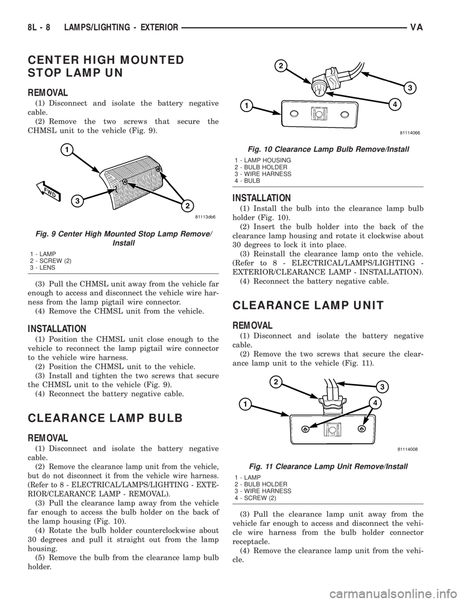
CHMSL unit to the vehicle (Fig. 9).
(3) Pull the CHMSL unit away from the vehicle far
enough to access and disconnect the vehicle wire har-
ness from the lamp pigtail wire connector.
(4) Remove the CHMSL unit from the vehicle.
INSTALLATION
(1) Position the CHMSL unit close enough to the
vehicle to reconnect the lamp pigtail wire connector
to the vehicle wire harness.
(2) Position the CHMSL unit to the vehicle.
(3) Install and tighten the two screws that secure
the CHMSL unit to the vehicle (Fig. 9).
(4) Reconnect the battery negative cable.
CLEARANCE LAMP BULB
REMOVAL
(1) Disconnect and isolate the battery negative
cable.
(2)
Remove the clearance lamp unit from the vehicle,
but do not disconnect it from the vehicle wire harness.
(Refer to 8 - ELECTRICAL/LAMPS/LIGHTING - EXTE-
RIOR/CLEARANCE LAMP - REMOVAL).
(3) Pull the clearance lamp away from the vehicle
far enough to access the bulb holder on the back of
the lamp housing (Fig. 10).
(4) Rotate the bulb holder counterclockwise about
30 degrees and pull it straight out from the lamp
housing.
(5) Remove the bulb from the clearance lamp bulb
holder.
INSTALLATION
(1) Install the bulb into the clearance lamp bulb
holder (Fig. 10).
(2) Insert the bulb holder into the back of the
clearance lamp housing and rotate it clockwise about
30 degrees to lock it into place.
(3) Reinstall the clearance lamp onto the vehicle.
(Refer to 8 - ELECTRICAL/LAMPS/LIGHTING -
EXTERIOR/CLEARANCE LAMP - INSTALLATION).
(4) Reconnect the battery negative cable.
CLEARANCE LAMP UNIT
REMOVAL
(1) Disconnect and isolate the battery negative
cable.
(2) Remove the two screws that secure the clear-
ance lamp unit to the vehicle (Fig. 11).
(3) Pull the clearance lamp unit away from the
vehicle far enough to access and disconnect the vehi-
cle wire harness from the bulb holder connector
receptacle.
(4) Remove the clearance lamp unit from the vehi-
cle.
Fig. 9 Center High Mounted Stop Lamp Remove/
Install
1 - LAMP
2 - SCREW (2)
3 - LENS
Fig. 10 Clearance Lamp Bulb Remove/Install
1 - LAMP HOUSING
2 - BULB HOLDER
3 - WIRE HARNESS
4 - BULB
Fig. 11 Clearance Lamp Unit Remove/Install
1 - LAMP
2 - BULB HOLDER
3 - WIRE HARNESS
4 - SCREW (2)
8L - 8 LAMPS/LIGHTING - EXTERIORVA
Page 207 of 1232
INSTALLATION
(1) Position the clearance lamp unit close enough
to the vehicle to reconnect the vehicle wire harness
to the bulb holder connector receptacle (Fig. 11).
(2) Position the clearance lamp unit to the vehicle.
(3) Install and tighten the two screws that secure
the clearance lamp unit to the vehicle.
(4) Reconnect the battery negative cable.
DAYTIME RUNNING LAMP
RELAY
REMOVAL
Daytime Running Lamps (DRL) are only used in
vehicles manufactured for the Canadian market,
where this is required equipment. On vehicles
equipped with DRL, a right and a left DRL relay are
each located in a dedicated connector of the vehicle
wire harness. Each connector is snapped into an
opening in a stamped sheet metal bracket which is
secured with screws within the driver side front seat
riser just beneath the seat riser cover panel.
WARNING: ON VEHICLES EQUIPPED WITH AIRBAGS,
DISABLE THE SUPPLEMENTAL RESTRAINT SYSTEM
BEFORE ATTEMPTING ANY STEERING WHEEL,
STEERING COLUMN, DRIVER AIRBAG, PASSENGER
AIRBAG, SEAT BELT TENSIONER, OR INSTRUMENT
PANEL COMPONENT DIAGNOSIS OR SERVICE. DIS-
CONNECT AND ISOLATE THE BATTERY NEGATIVE
(GROUND) CABLE, THEN WAIT TWO MINUTES FOR
THE SYSTEM CAPACITOR TO DISCHARGE BEFORE
PERFORMING FURTHER DIAGNOSIS OR SERVICE.
THIS IS THE ONLY SURE WAY TO DISABLE THE SUP-
PLEMENTAL RESTRAINT SYSTEM. FAILURE TO TAKE
THE PROPER PRECAUTIONS COULD RESULT IN
ACCIDENTAL AIRBAG DEPLOYMENT AND POSSIBLE
PERSONAL INJURY.
(1) Disconnect and isolate the battery negative
cable.
(2) Move the driver side front seat to its most for-
ward position for easiest access to the seat riser
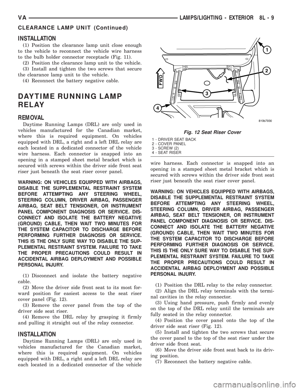
cover panel (Fig. 12).
(3) Remove the cover panel from the top of the
driver side seat riser.
(4) Remove the DRL relay by grasping it firmly
and pulling it straight out of the relay connector.
INSTALLATION
Daytime Running Lamps (DRL) are only used in
vehicles manufactured for the Canadian market,
where this is required equipment. On vehicles
equipped with DRL, a right and a left DRL relay are
each located in a dedicated connector of the vehiclewire harness. Each connector is snapped into an
opening in a stamped sheet metal bracket which is
secured with screws within the driver side front seat
riser just beneath the seat riser cover panel.
WARNING: ON VEHICLES EQUIPPED WITH AIRBAGS,
DISABLE THE SUPPLEMENTAL RESTRAINT SYSTEM
BEFORE ATTEMPTING ANY STEERING WHEEL,
STEERING COLUMN, DRIVER AIRBAG, PASSENGER
AIRBAG, SEAT BELT TENSIONER, OR INSTRUMENT
PANEL COMPONENT DIAGNOSIS OR SERVICE. DIS-
CONNECT AND ISOLATE THE BATTERY NEGATIVE
(GROUND) CABLE, THEN WAIT TWO MINUTES FOR
THE SYSTEM CAPACITOR TO DISCHARGE BEFORE
PERFORMING FURTHER DIAGNOSIS OR SERVICE.
THIS IS THE ONLY SURE WAY TO DISABLE THE SUP-
PLEMENTAL RESTRAINT SYSTEM. FAILURE TO TAKE
THE PROPER PRECAUTIONS COULD RESULT IN
ACCIDENTAL AIRBAG DEPLOYMENT AND POSSIBLE
PERSONAL INJURY.
(1) Position the DRL relay to the relay connector.
(2) Align the DRL relay terminals with the termi-
nal cavities in the relay connector.
(3) Using hand pressure, push firmly and evenly
on the top of the DRL relay until the terminals are
fully seated in the relay connector.
(4) Position the cover panel onto the top of the
driver side seat riser (Fig. 12).
(5) Install and tighten the two screws that secure
the cover panel to the top of the seat riser under the
driver side front seat.
(6) Move the driver side front seat back to its driv-
ing position.
(7) Reconnect the battery negative cable.
Fig. 12 Seat Riser Cover
1 - DRIVER SEAT BACK
2 - COVER PANEL
3 - SCREW (2)
4 - SEAT RISER
VALAMPS/LIGHTING - EXTERIOR 8L - 9
CLEARANCE LAMP UNIT (Continued)
Page 208 of 1232
FOG LAMP BULB
REMOVAL
(1) Disconnect and isolate the battery negative
cable.
(2) Disengage and swing the retainers that secure
the front lamp unit rear cover to each side of the
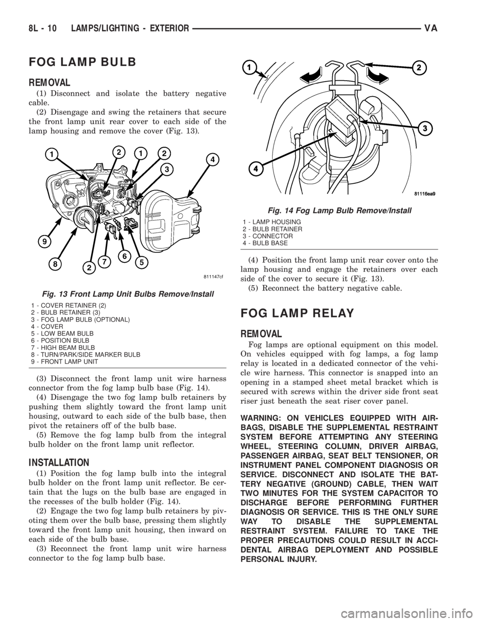
lamp housing and remove the cover (Fig. 13).
(3) Disconnect the front lamp unit wire harness
connector from the fog lamp bulb base (Fig. 14).
(4) Disengage the two fog lamp bulb retainers by
pushing them slightly toward the front lamp unit
housing, outward to each side of the bulb base, then
pivot the retainers off of the bulb base.
(5) Remove the fog lamp bulb from the integral
bulb holder on the front lamp unit reflector.
INSTALLATION
(1) Position the fog lamp bulb into the integral
bulb holder on the front lamp unit reflector. Be cer-
tain that the lugs on the bulb base are engaged in
the recesses of the bulb holder (Fig. 14).
(2) Engage the two fog lamp bulb retainers by piv-
oting them over the bulb base, pressing them slightly
toward the front lamp unit housing, then inward on
each side of the bulb base.
(3) Reconnect the front lamp unit wire harness
connector to the fog lamp bulb base.(4) Position the front lamp unit rear cover onto the
lamp housing and engage the retainers over each
side of the cover to secure it (Fig. 13).
(5) Reconnect the battery negative cable.
FOG LAMP RELAY
REMOVAL
Fog lamps are optional equipment on this model.
On vehicles equipped with fog lamps, a fog lamp
relay is located in a dedicated connector of the vehi-
cle wire harness. This connector is snapped into an
opening in a stamped sheet metal bracket which is
secured with screws within the driver side front seat
riser just beneath the seat riser cover panel.
WARNING: ON VEHICLES EQUIPPED WITH AIR-
BAGS, DISABLE THE SUPPLEMENTAL RESTRAINT
SYSTEM BEFORE ATTEMPTING ANY STEERING
WHEEL, STEERING COLUMN, DRIVER AIRBAG,
PASSENGER AIRBAG, SEAT BELT TENSIONER, OR
INSTRUMENT PANEL COMPONENT DIAGNOSIS OR
SERVICE. DISCONNECT AND ISOLATE THE BAT-
TERY NEGATIVE (GROUND) CABLE, THEN WAIT
TWO MINUTES FOR THE SYSTEM CAPACITOR TO
DISCHARGE BEFORE PERFORMING FURTHER
DIAGNOSIS OR SERVICE. THIS IS THE ONLY SURE
WAY TO DISABLE THE SUPPLEMENTAL
RESTRAINT SYSTEM. FAILURE TO TAKE THE
PROPER PRECAUTIONS COULD RESULT IN ACCI-
DENTAL AIRBAG DEPLOYMENT AND POSSIBLE
PERSONAL INJURY.
Fig. 13 Front Lamp Unit Bulbs Remove/Install
1 - COVER RETAINER (2)
2 - BULB RETAINER (3)
3 - FOG LAMP BULB (OPTIONAL)
4 - COVER
5 - LOW BEAM BULB
6 - POSITION BULB
7 - HIGH BEAM BULB
8 - TURN/PARK/SIDE MARKER BULB
9 - FRONT LAMP UNIT
Fig. 14 Fog Lamp Bulb Remove/Install
1 - LAMP HOUSING
2 - BULB RETAINER
3 - CONNECTOR
4 - BULB BASE
8L - 10 LAMPS/LIGHTING - EXTERIORVA
Page 209 of 1232
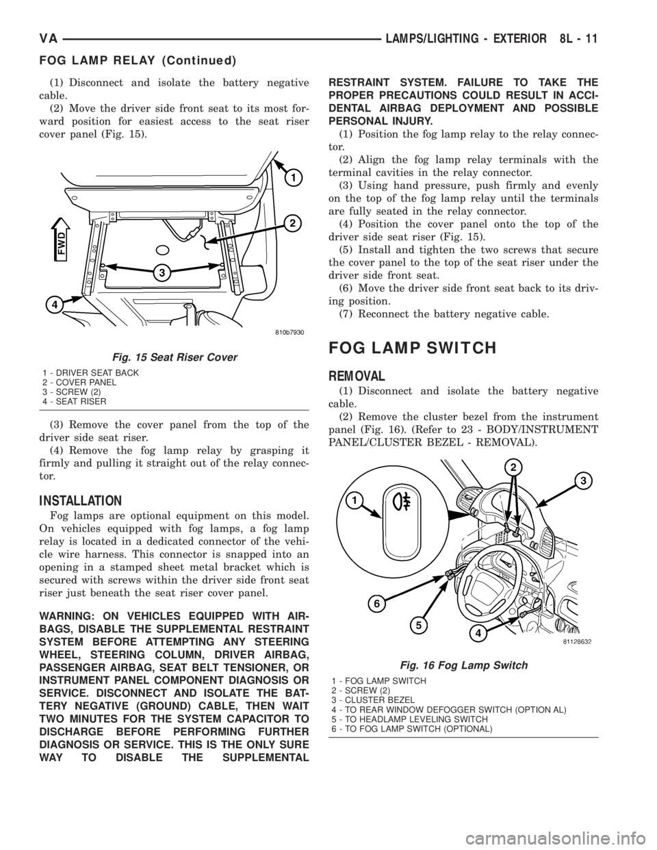
(1) Disconnect and isolate the battery negative
cable.
(2) Move the driver side front seat to its most for-
ward position for easiest access to the seat riser
cover panel (Fig. 15).
(3) Remove the cover panel from the top of the
driver side seat riser.
(4) Remove the fog lamp relay by grasping it
firmly and pulling it straight out of the relay connec-
tor.
INSTALLATION
Fog lamps are optional equipment on this model.
On vehicles equipped with fog lamps, a fog lamp
relay is located in a dedicated connector of the vehi-
cle wire harness. This connector is snapped into an
opening in a stamped sheet metal bracket which is
secured with screws within the driver side front seat
riser just beneath the seat riser cover panel.
WARNING: ON VEHICLES EQUIPPED WITH AIR-
BAGS, DISABLE THE SUPPLEMENTAL RESTRAINT
SYSTEM BEFORE ATTEMPTING ANY STEERING
WHEEL, STEERING COLUMN, DRIVER AIRBAG,
PASSENGER AIRBAG, SEAT BELT TENSIONER, OR
INSTRUMENT PANEL COMPONENT DIAGNOSIS OR
SERVICE. DISCONNECT AND ISOLATE THE BAT-
TERY NEGATIVE (GROUND) CABLE, THEN WAIT
TWO MINUTES FOR THE SYSTEM CAPACITOR TO
DISCHARGE BEFORE PERFORMING FURTHER
DIAGNOSIS OR SERVICE. THIS IS THE ONLY SURE
WAY TO DISABLE THE SUPPLEMENTALRESTRAINT SYSTEM. FAILURE TO TAKE THE
PROPER PRECAUTIONS COULD RESULT IN ACCI-
DENTAL AIRBAG DEPLOYMENT AND POSSIBLE
PERSONAL INJURY.
(1) Position the fog lamp relay to the relay connec-
tor.
(2) Align the fog lamp relay terminals with the
terminal cavities in the relay connector.
(3) Using hand pressure, push firmly and evenly
on the top of the fog lamp relay until the terminals
are fully seated in the relay connector.
(4) Position the cover panel onto the top of the
driver side seat riser (Fig. 15).
(5) Install and tighten the two screws that secure
the cover panel to the top of the seat riser under the
driver side front seat.
(6) Move the driver side front seat back to its driv-
ing position.
(7) Reconnect the battery negative cable.
FOG LAMP SWITCH
REMOVAL
(1) Disconnect and isolate the battery negative
cable.
(2) Remove the cluster bezel from the instrument
panel (Fig. 16). (Refer to 23 - BODY/INSTRUMENT
PANEL/CLUSTER BEZEL - REMOVAL).
Fig. 15 Seat Riser Cover
1 - DRIVER SEAT BACK
2 - COVER PANEL
3 - SCREW (2)
4 - SEAT RISER
Fig. 16 Fog Lamp Switch
1 - FOG LAMP SWITCH
2 - SCREW (2)
3 - CLUSTER BEZEL
4 - TO REAR WINDOW DEFOGGER SWITCH (OPTION AL)
5 - TO HEADLAMP LEVELING SWITCH
6 - TO FOG LAMP SWITCH (OPTIONAL)
VALAMPS/LIGHTING - EXTERIOR 8L - 11
FOG LAMP RELAY (Continued)
Page 210 of 1232
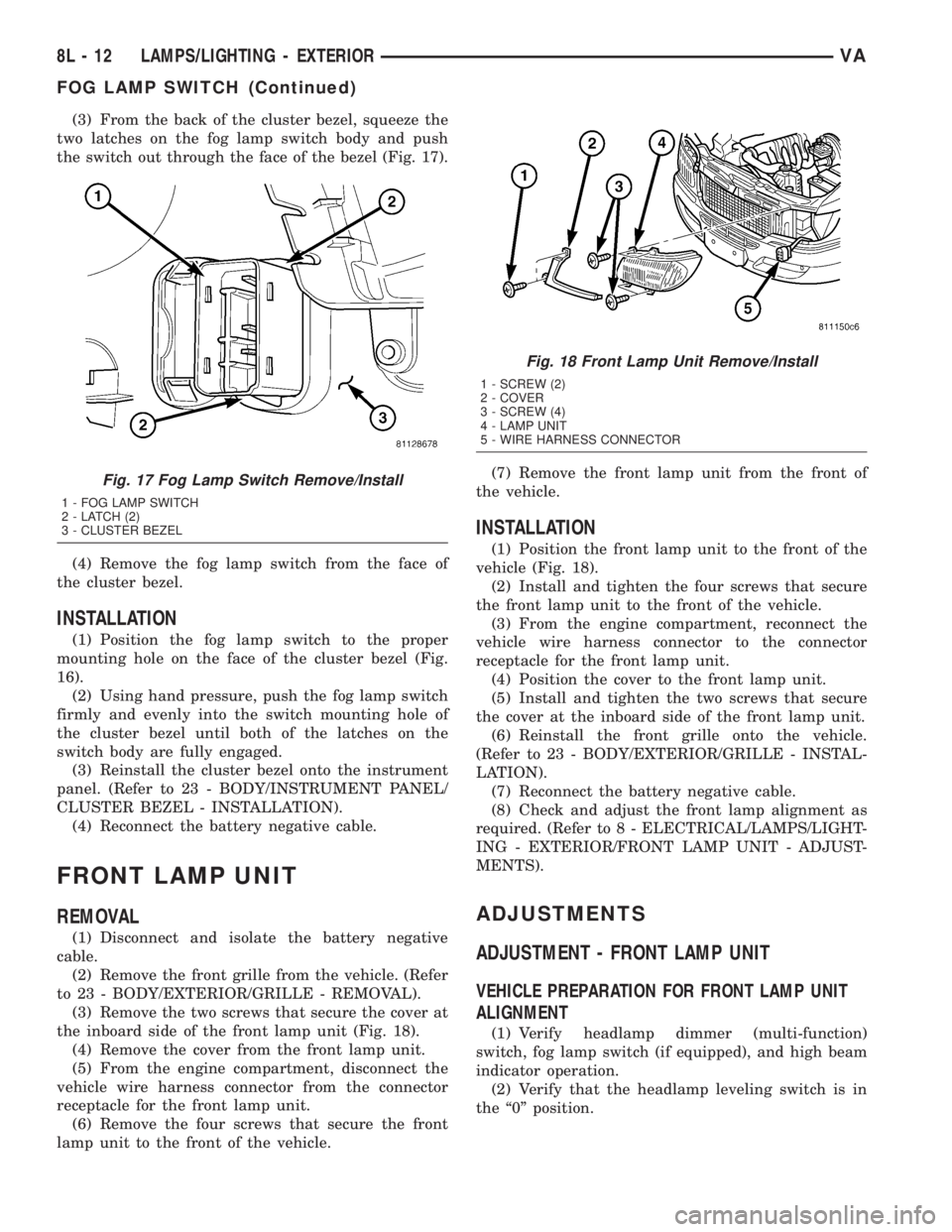
(3) From the back of the cluster bezel, squeeze the
two latches on the fog lamp switch body and push
the switch out through the face of the bezel (Fig. 17).
(4) Remove the fog lamp switch from the face of
the cluster bezel.
INSTALLATION
(1) Position the fog lamp switch to the proper
mounting hole on the face of the cluster bezel (Fig.
16).
(2) Using hand pressure, push the fog lamp switch
firmly and evenly into the switch mounting hole of
the cluster bezel until both of the latches on the
switch body are fully engaged.
(3) Reinstall the cluster bezel onto the instrument
panel. (Refer to 23 - BODY/INSTRUMENT PANEL/
CLUSTER BEZEL - INSTALLATION).
(4) Reconnect the battery negative cable.
FRONT LAMP UNIT
REMOVAL
(1) Disconnect and isolate the battery negative
cable.
(2) Remove the front grille from the vehicle. (Refer
to 23 - BODY/EXTERIOR/GRILLE - REMOVAL).
(3) Remove the two screws that secure the cover at
the inboard side of the front lamp unit (Fig. 18).
(4) Remove the cover from the front lamp unit.
(5) From the engine compartment, disconnect the
vehicle wire harness connector from the connector
receptacle for the front lamp unit.
(6) Remove the four screws that secure the front
lamp unit to the front of the vehicle.(7) Remove the front lamp unit from the front of
the vehicle.
INSTALLATION
(1) Position the front lamp unit to the front of the
vehicle (Fig. 18).
(2) Install and tighten the four screws that secure
the front lamp unit to the front of the vehicle.
(3) From the engine compartment, reconnect the
vehicle wire harness connector to the connector
receptacle for the front lamp unit.
(4) Position the cover to the front lamp unit.
(5) Install and tighten the two screws that secure
the cover at the inboard side of the front lamp unit.
(6) Reinstall the front grille onto the vehicle.
(Refer to 23 - BODY/EXTERIOR/GRILLE - INSTAL-
LATION).
(7) Reconnect the battery negative cable.
(8) Check and adjust the front lamp alignment as
required. (Refer to 8 - ELECTRICAL/LAMPS/LIGHT-
ING - EXTERIOR/FRONT LAMP UNIT - ADJUST-
MENTS).
ADJUSTMENTS
ADJUSTMENT - FRONT LAMP UNIT
VEHICLE PREPARATION FOR FRONT LAMP UNIT
ALIGNMENT
(1) Verify headlamp dimmer (multi-function)
switch, fog lamp switch (if equipped), and high beam
indicator operation.
(2) Verify that the headlamp leveling switch is in
the ª0º position.
Fig. 17 Fog Lamp Switch Remove/Install
1 - FOG LAMP SWITCH
2 - LATCH (2)
3 - CLUSTER BEZEL
Fig. 18 Front Lamp Unit Remove/Install
1 - SCREW (2)
2 - COVER
3 - SCREW (4)
4 - LAMP UNIT
5 - WIRE HARNESS CONNECTOR
8L - 12 LAMPS/LIGHTING - EXTERIORVA
FOG LAMP SWITCH (Continued)