MERCEDES-BENZ SPRINTER 2005 Service Repair Manual
Manufacturer: MERCEDES-BENZ, Model Year: 2005, Model line: SPRINTER, Model: MERCEDES-BENZ SPRINTER 2005Pages: 1232, PDF Size: 39.23 MB
Page 781 of 1232
NOTE: Do Not mix up the top and bottom connect-
ing rod bearing shells.
(8) Mark the connecting rod bearing shell and the
connecting rod bearing cap to each other.
NOTE: If the pistons are used, the direction of
travel arrows and the marking of the pistons may
no longer be visible because of carbon deposits.
The carbon deposits on the pistons must be
removed.
NOTE: If the arrows indicating the driving direction
on the piston are no longer visible, they must be
marked again.
(9) Remove the connecting rod together with the
piston through the top of the engine.NOTE: DO NOT mix up the top and bottom connect-
ing rod bearing shells.
(10) Mark the connecting rod bearing shell and
connecting rod to each other.
CAUTION: Care must be taken not to damage the
piston.
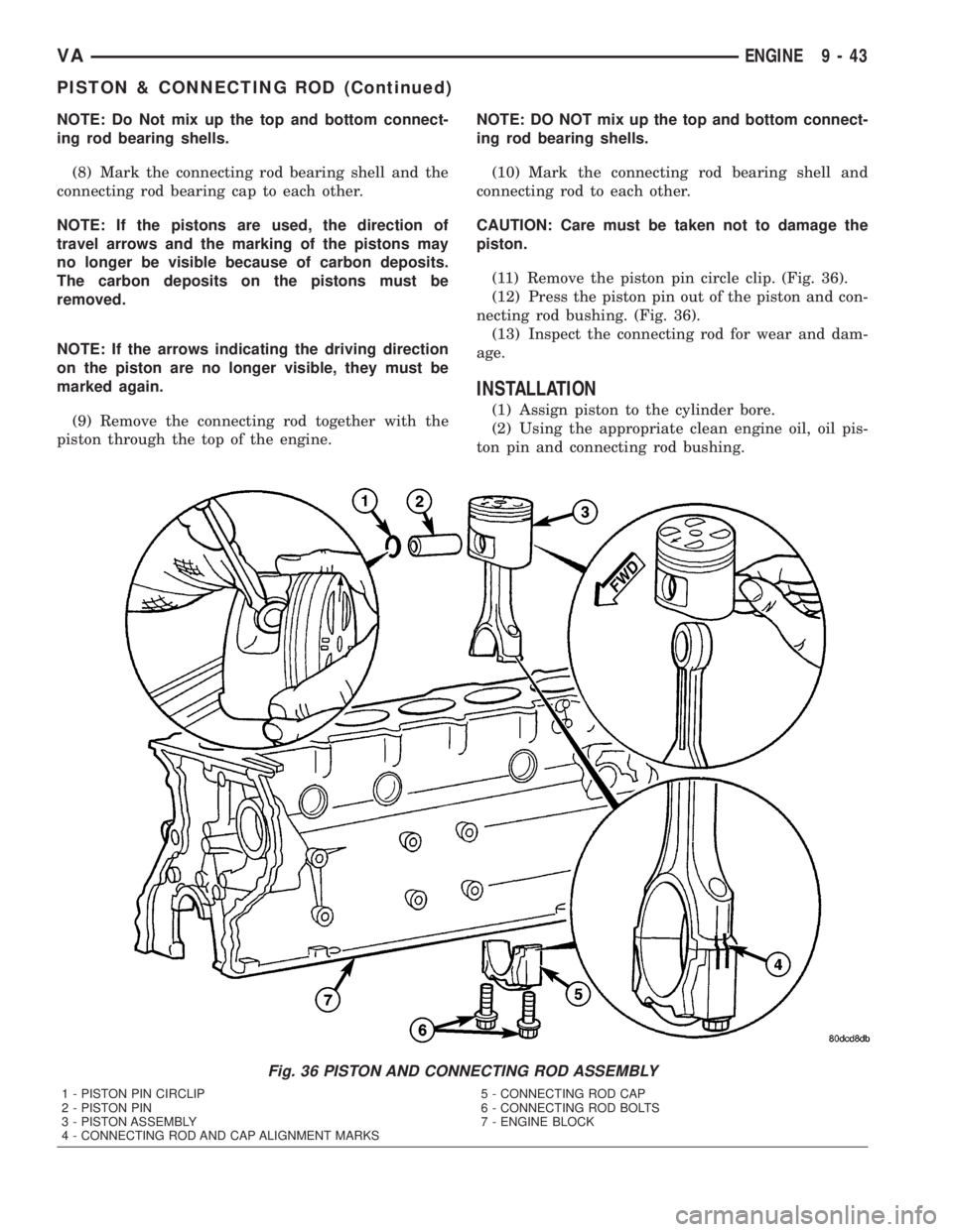
(11) Remove the piston pin circle clip. (Fig. 36).
(12) Press the piston pin out of the piston and con-
necting rod bushing. (Fig. 36).
(13) Inspect the connecting rod for wear and dam-
age.
INSTALLATION
(1) Assign piston to the cylinder bore.
(2) Using the appropriate clean engine oil, oil pis-
ton pin and connecting rod bushing.
Fig. 36 PISTON AND CONNECTING ROD ASSEMBLY
1 - PISTON PIN CIRCLIP
2 - PISTON PIN
3 - PISTON ASSEMBLY
4 - CONNECTING ROD AND CAP ALIGNMENT MARKS5 - CONNECTING ROD CAP
6 - CONNECTING ROD BOLTS
7 - ENGINE BLOCK
VAENGINE 9 - 43
PISTON & CONNECTING ROD (Continued)
Page 782 of 1232
CAUTION: Assemble the piston and connecting rod
so that the arrow is pointing in the direction of
travel (in the opposite direction of power flow). The
marking on the connecting rod is pointing toward
the inlet side.
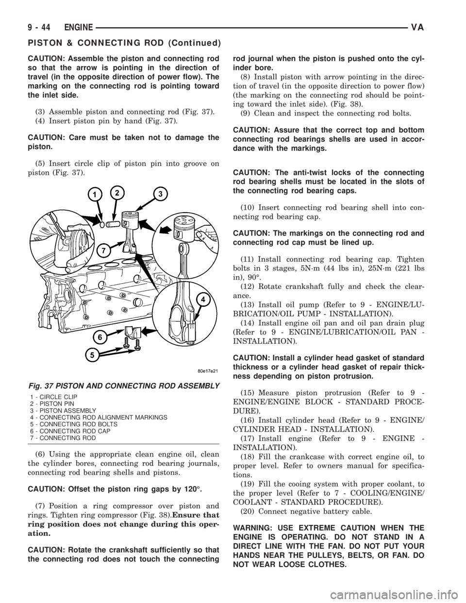
(3) Assemble piston and connecting rod (Fig. 37).
(4) Insert piston pin by hand (Fig. 37).
CAUTION: Care must be taken not to damage the
piston.
(5) Insert circle clip of piston pin into groove on
piston (Fig. 37).
(6) Using the appropriate clean engine oil, clean
the cylinder bores, connecting rod bearing journals,
connecting rod bearing shells and pistons.
CAUTION: Offset the piston ring gaps by 120É.
(7) Position a ring compressor over piston and
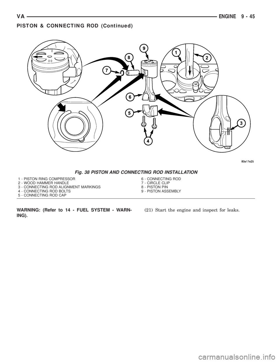
rings. Tighten ring compressor (Fig. 38).Ensure that
ring position does not change during this oper-
ation.
CAUTION: Rotate the crankshaft sufficiently so that
the connecting rod does not touch the connectingrod journal when the piston is pushed onto the cyl-
inder bore.
(8) Install piston with arrow pointing in the direc-
tion of travel (in the opposite direction to power flow)
(the marking on the connecting rod should be point-
ing toward the inlet side). (Fig. 38).
(9) Clean and inspect the connecting rod bolts.
CAUTION: Assure that the correct top and bottom
connecting rod bearings shells are used in accor-
dance with the markings.
CAUTION: The anti-twist locks of the connecting
rod bearing shells must be located in the slots of
the connecting rod bearing caps.
(10) Insert connecting rod bearing shell into con-
necting rod bearing cap.
CAUTION: The markings on the connecting rod and
connecting rod cap must be lined up.
(11) Install connecting rod bearing cap. Tighten
bolts in 3 stages, 5N´m (44 lbs in), 25N´m (221 lbs
in), 90É.
(12) Rotate crankshaft fully and check the clear-
ance.
(13) Install oil pump (Refer to 9 - ENGINE/LU-
BRICATION/OIL PUMP - INSTALLATION).
(14) Install engine oil pan and oil pan drain plug
(Refer to 9 - ENGINE/LUBRICATION/OIL PAN -
INSTALLATION).
CAUTION: Install a cylinder head gasket of standard
thickness or a cylinder head gasket of repair thick-
ness depending on piston protrusion.
(15) Measure piston protrusion (Refer to 9 -
ENGINE/ENGINE BLOCK - STANDARD PROCE-
DURE).
(16) Install cylinder head (Refer to 9 - ENGINE/
CYLINDER HEAD - INSTALLATION).
(17) Install engine (Refer to 9 - ENGINE -
INSTALLATION).
(18) Fill the crankcase with correct engine oil, to
proper level. Refer to owners manual for specifica-
tions.
(19) Fill the cooing system with proper coolant, to
the proper level (Refer to 7 - COOLING/ENGINE/
COOLANT - STANDARD PROCEDURE).
(20) Connect negative battery cable.
WARNING: USE EXTREME CAUTION WHEN THE
ENGINE IS OPERATING. DO NOT STAND IN A
DIRECT LINE WITH THE FAN. DO NOT PUT YOUR
HANDS NEAR THE PULLEYS, BELTS, OR FAN. DO
NOT WEAR LOOSE CLOTHES.
Fig. 37 PISTON AND CONNECTING ROD ASSEMBLY
1 - CIRCLE CLIP
2 - PISTON PIN
3 - PISTON ASSEMBLY
4 - CONNECTING ROD ALIGNMENT MARKINGS
5 - CONNECTING ROD BOLTS
6 - CONNECTING ROD CAP
7 - CONNECTING ROD
9 - 44 ENGINEVA
PISTON & CONNECTING ROD (Continued)
Page 783 of 1232
WARNING: (Refer to 14 - FUEL SYSTEM - WARN-
ING).(21) Start the engine and inspect for leaks.
Fig. 38 PISTON AND CONNECTING ROD INSTALLATION
1 - PISTON RING COMPRESSOR
2 - WOOD HAMMER HANDLE
3 - CONNECTING ROD ALIGNMENT MARKINGS
4 - CONNECTING ROD BOLTS
5 - CONNECTING ROD CAP6 - CONNECTING ROD
7 - CIRCLE CLIP
8 - PISTON PIN
9 - PISTON ASSEMBLY
VAENGINE 9 - 45
PISTON & CONNECTING ROD (Continued)
Page 784 of 1232
PISTON RINGS
STANDARD PROCEDURE - PISTON RING
FITTING
(1) Carefully clean the carbon from all ring
grooves. Oil drain openings in the oil ring groove and
pin boss must be clear. DO NOT remove metal from
the grooves or lands. This will change ring-to-groove
clearances and will damage the ring-to-land seating.
(2) Be sure the piston ring grooves are free of
nicks and burrs.
(3) Measure the ring side clearance with a feeler
gauge fitted snugly between the ring land and ring
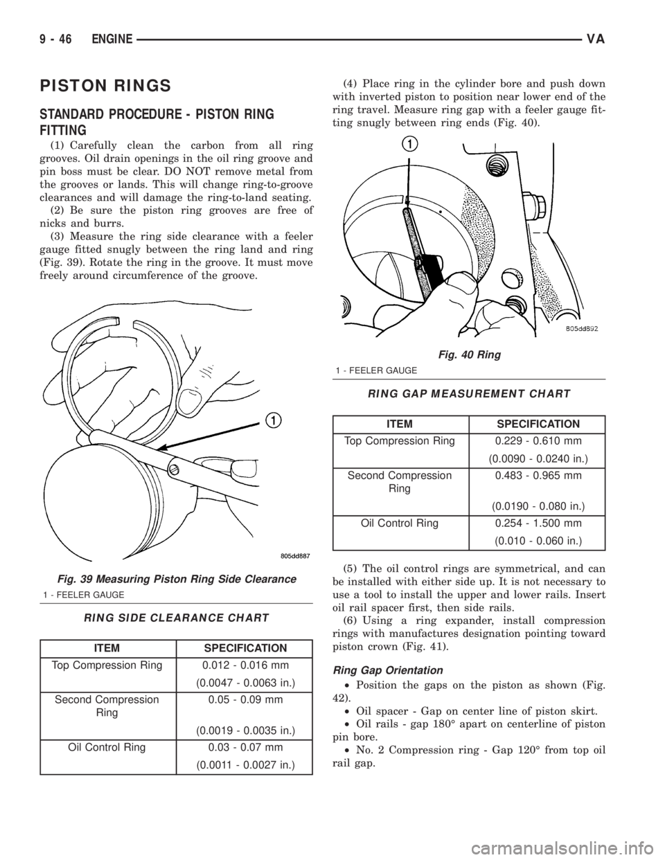
(Fig. 39). Rotate the ring in the groove. It must move
freely around circumference of the groove.
RING SIDE CLEARANCE CHART
ITEM SPECIFICATION
Top Compression Ring 0.012 - 0.016 mm
(0.0047 - 0.0063 in.)
Second Compression
Ring0.05 - 0.09 mm
(0.0019 - 0.0035 in.)
Oil Control Ring 0.03 - 0.07 mm
(0.0011 - 0.0027 in.)(4) Place ring in the cylinder bore and push down
with inverted piston to position near lower end of the
ring travel. Measure ring gap with a feeler gauge fit-
ting snugly between ring ends (Fig. 40).
RING GAP MEASUREMENT CHART
ITEM SPECIFICATION
Top Compression Ring 0.229 - 0.610 mm
(0.0090 - 0.0240 in.)
Second Compression
Ring0.483 - 0.965 mm
(0.0190 - 0.080 in.)
Oil Control Ring 0.254 - 1.500 mm
(0.010 - 0.060 in.)
(5) The oil control rings are symmetrical, and can
be installed with either side up. It is not necessary to
use a tool to install the upper and lower rails. Insert
oil rail spacer first, then side rails.
(6) Using a ring expander, install compression
rings with manufactures designation pointing toward
piston crown (Fig. 41).
Ring Gap Orientation
²Position the gaps on the piston as shown (Fig.
42).
²Oil spacer - Gap on center line of piston skirt.
²Oil rails - gap 180É apart on centerline of piston
pin bore.
²No. 2 Compression ring - Gap 120É from top oil
rail gap.
Fig. 39 Measuring Piston Ring Side Clearance
1 - FEELER GAUGE
Fig. 40 Ring
1 - FEELER GAUGE
9 - 46 ENGINEVA
Page 785 of 1232
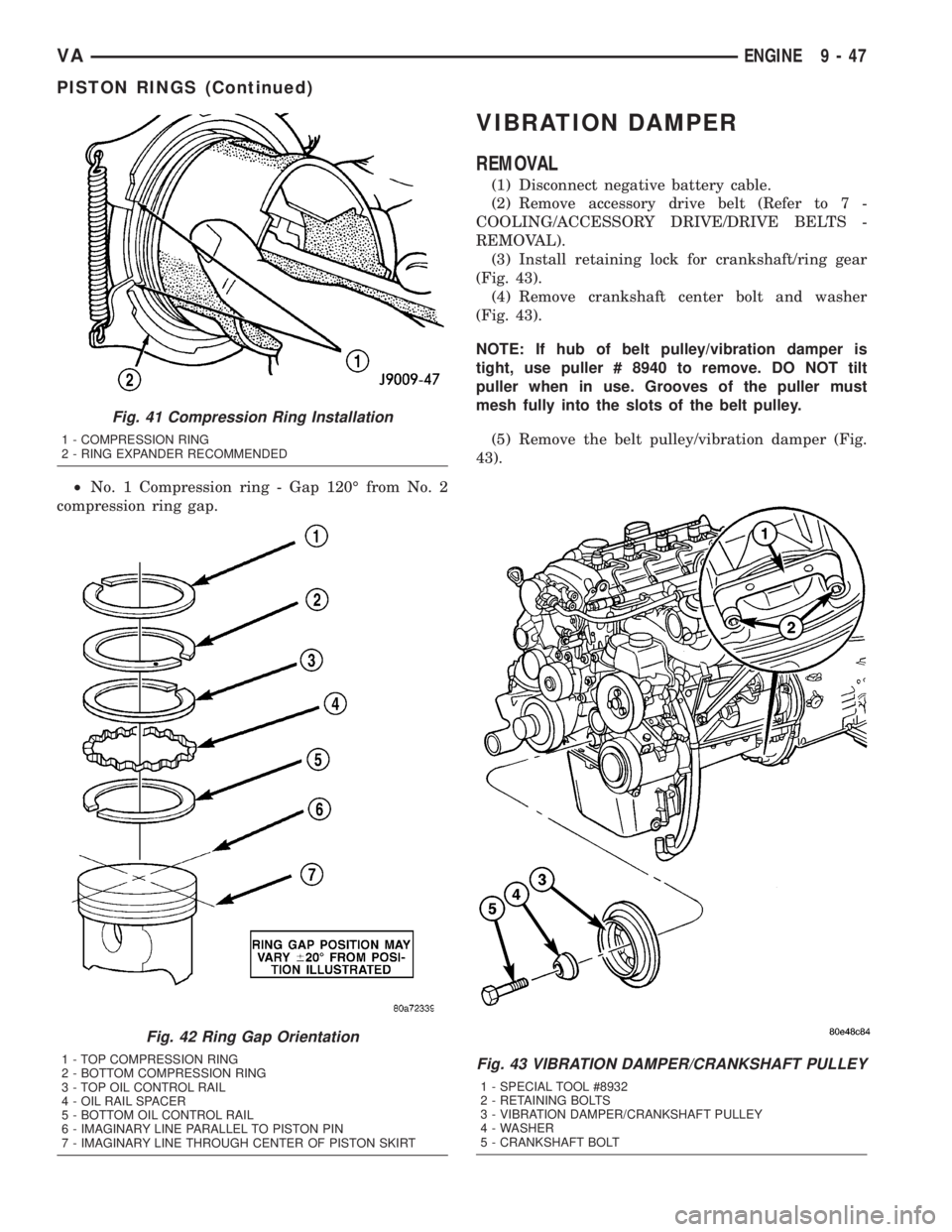
²No. 1 Compression ring - Gap 120É from No. 2
compression ring gap.
VIBRATION DAMPER
REMOVAL
(1) Disconnect negative battery cable.
(2) Remove accessory drive belt (Refer to 7 -
COOLING/ACCESSORY DRIVE/DRIVE BELTS -
REMOVAL).
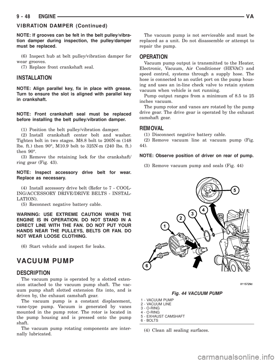
(3) Install retaining lock for crankshaft/ring gear
(Fig. 43).
(4) Remove crankshaft center bolt and washer
(Fig. 43).
NOTE: If hub of belt pulley/vibration damper is
tight, use puller # 8940 to remove. DO NOT tilt
puller when in use. Grooves of the puller must
mesh fully into the slots of the belt pulley.
(5) Remove the belt pulley/vibration damper (Fig.
43).
Fig. 41 Compression Ring Installation
1 - COMPRESSION RING
2 - RING EXPANDER RECOMMENDED
Fig. 42 Ring Gap Orientation
1 - TOP COMPRESSION RING
2 - BOTTOM COMPRESSION RING
3 - TOP OIL CONTROL RAIL
4 - OIL RAIL SPACER
5 - BOTTOM OIL CONTROL RAIL
6 - IMAGINARY LINE PARALLEL TO PISTON PIN
7 - IMAGINARY LINE THROUGH CENTER OF PISTON SKIRTFig. 43 VIBRATION DAMPER/CRANKSHAFT PULLEY
1 - SPECIAL TOOL #8932
2 - RETAINING BOLTS
3 - VIBRATION DAMPER/CRANKSHAFT PULLEY
4 - WASHER
5 - CRANKSHAFT BOLT
VAENGINE 9 - 47
PISTON RINGS (Continued)
Page 786 of 1232
NOTE: If grooves can be felt in the belt pulley/vibra-
tion damper during inspection, the pulley/damper
must be replaced.
(6) Inspect hub at belt pulley/vibration damper for
wear grooves.
(7) Replace front crankshaft seal.
INSTALLATION
NOTE: Align parallel key, fix in place with grease.
Turn to ensure the slot is aligned with parallel key
in crankshaft.
NOTE: Front crankshaft seal must be replaced
before installing the belt pulley/vibration damper.
(1) Position the belt pulley/vibration damper.
(2) Install crankshaft center bolt and washer.
Tighten bolt in two stages. M8.8 bolt to 200N´m (148
lbs. ft.) then 90É, M10.9 bolt to 325N´m (240 lbs. ft.)
then 90É.
(3) Remove the retaining lock for the crankshaft/
ring gear (Fig. 43).
NOTE: Inspect accessory drive belt for wear.
Replace as necessary.
(4) Install accessory drive belt (Refer to 7 - COOL-
ING/ACCESSORY DRIVE/DRIVE BELTS - INSTAL-
LATION).
(5) Reconnect negative battery cable.
WARNING: USE EXTREME CAUTION WHEN THE
ENGINE IS IN OPERATION. DO NOT STAND IN A
DIRECT LINE WITH THE FAN. DO NOT PUT YOUR
HANDS NEAR THE PULLEYS, BELTS OR FAN. DO
NOT WEAR LOOSE CLOTHING.
(6) Start vehicle and inspect for leaks.
VACUUM PUMP
DESCRIPTION
The vacuum pump is operated by a slotted exten-
sion attached to the vacuum pump shaft. The vac-
uum pump shaft slotted extension fits into, and is
driven by, the exhaust camshaft gear.
The vacuum pump is a constant displacement,
vane-type pump. Vacuum is generated by vanes
mounted in the pump rotor. The rotor is located in
the pump housing and is pressed onto the pump
shaft.
The vacuum pump rotating components are inter-
nally lubricated.The vacuum pump is not serviceable and must be
replaced as a unit. Do not disassemble or attempt to
repair the pump.
OPERATION
Vacuum pump output is transmitted to the Heater,
Electronic, Vacuum, Air Conditioner (HEVAC) and
speed control, systems through a supply hose. The
hose is connected to an outlet port on the pump hous-
ing and uses an in-line check valve to retain system
vacuum when vehicle is not running.
Pump output ranges from a minimum of 8.5 to 25
inches vacuum.
The pump rotor and vanes are rotated by the pump
drive gear. The drive gear is operated by the exhaust
camshaft gear.
REMOVAL
(1) Disconnect negative battery cable.
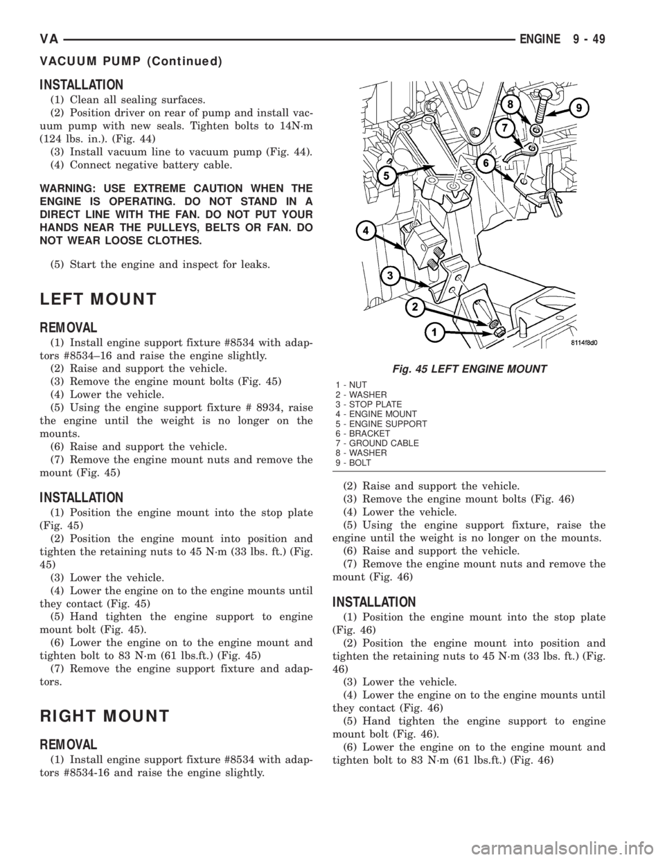
(2) Remove vacuum line at vacuum pump (Fig.
44).
NOTE: Observe position of driver on rear of pump.
(3) Remove vacuum pump and seals (Fig. 44)
(4) Clean all sealing surfaces.
Fig. 44 VACUUM PUMP
1 - VACUUM PUMP
2 - VACUUM LINE
3 - O-RING
4 - O-RING
5 - EXHAUST CAMSHAFT
6 - BOLTS
9 - 48 ENGINEVA
VIBRATION DAMPER (Continued)
Page 787 of 1232
INSTALLATION
(1) Clean all sealing surfaces.
(2) Position driver on rear of pump and install vac-
uum pump with new seals. Tighten bolts to 14N´m
(124 lbs. in.). (Fig. 44)
(3) Install vacuum line to vacuum pump (Fig. 44).
(4) Connect negative battery cable.
WARNING: USE EXTREME CAUTION WHEN THE
ENGINE IS OPERATING. DO NOT STAND IN A
DIRECT LINE WITH THE FAN. DO NOT PUT YOUR
HANDS NEAR THE PULLEYS, BELTS OR FAN. DO
NOT WEAR LOOSE CLOTHES.
(5) Start the engine and inspect for leaks.
LEFT MOUNT
REMOVAL
(1) Install engine support fixture #8534 with adap-
tors #8534±16 and raise the engine slightly.
(2) Raise and support the vehicle.
(3) Remove the engine mount bolts (Fig. 45)
(4) Lower the vehicle.
(5) Using the engine support fixture # 8934, raise
the engine until the weight is no longer on the
mounts.
(6) Raise and support the vehicle.
(7) Remove the engine mount nuts and remove the
mount (Fig. 45)
INSTALLATION
(1) Position the engine mount into the stop plate
(Fig. 45)
(2) Position the engine mount into position and
tighten the retaining nuts to 45 N´m (33 lbs. ft.) (Fig.
45)
(3) Lower the vehicle.
(4) Lower the engine on to the engine mounts until
they contact (Fig. 45)
(5) Hand tighten the engine support to engine
mount bolt (Fig. 45).
(6) Lower the engine on to the engine mount and
tighten bolt to 83 N´m (61 lbs.ft.) (Fig. 45)
(7) Remove the engine support fixture and adap-
tors.
RIGHT MOUNT
REMOVAL
(1) Install engine support fixture #8534 with adap-
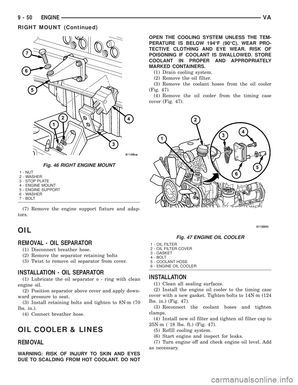
tors #8534-16 and raise the engine slightly.(2) Raise and support the vehicle.
(3) Remove the engine mount bolts (Fig. 46)
(4) Lower the vehicle.
(5) Using the engine support fixture, raise the
engine until the weight is no longer on the mounts.
(6) Raise and support the vehicle.
(7) Remove the engine mount nuts and remove the
mount (Fig. 46)
INSTALLATION
(1) Position the engine mount into the stop plate
(Fig. 46)
(2) Position the engine mount into position and
tighten the retaining nuts to 45 N´m (33 lbs. ft.) (Fig.
46)
(3) Lower the vehicle.
(4) Lower the engine on to the engine mounts until
they contact (Fig. 46)
(5) Hand tighten the engine support to engine
mount bolt (Fig. 46).
(6) Lower the engine on to the engine mount and
tighten bolt to 83 N´m (61 lbs.ft.) (Fig. 46)
Fig. 45 LEFT ENGINE MOUNT
1 - NUT
2 - WASHER
3 - STOP PLATE
4 - ENGINE MOUNT
5 - ENGINE SUPPORT
6 - BRACKET
7 - GROUND CABLE
8 - WASHER
9 - BOLT
VAENGINE 9 - 49
VACUUM PUMP (Continued)
Page 788 of 1232
(7) Remove the engine support fixture and adap-
tors.
OIL
REMOVAL - OIL SEPARATOR
(1) Disconnect breather hose.
(2) Remove the separator retaining bolts
(3) Twist to remove oil separator from cover.
INSTALLATION - OIL SEPARATOR
(1) Lubricate the oil separator o - ring with clean
engine oil.
(2) Position separator above cover and apply down-
ward pressure to seat.
(3) Install retaining bolts and tighten to 8N´m (70
lbs. in.).
(4) Connect breather hose.
OIL COOLER & LINES
REMOVAL
WARNING: RISK OF INJURY TO SKIN AND EYES
DUE TO SCALDING FROM HOT COOLANT. DO NOTOPEN THE COOLING SYSTEM UNLESS THE TEM-
PERATURE IS BELOW 194ÉF (90ÉC). WEAR PRO-
TECTIVE CLOTHING AND EYE WEAR. RISK OF
POISONING IF COOLANT IS SWALLOWED. STORE
COOLANT IN PROPER AND APPROPRIATELY
MARKED CONTAINERS.
(1) Drain cooling system.
(2) Remove the oil filter.
(3) Remove the coolant hoses from the oil cooler
(Fig. 47).
(4) Remove the oil cooler from the timing case
cover (Fig. 47).
INSTALLATION
(1) Clean all sealing surfaces.
(2) Install the engine oil cooler to the timing case
cover with a new gasket. Tighten bolts to 14N´m (124
lbs. in.) (Fig. 47).
(3) Reconnect the coolant hoses and tighten
clamps.
(4) Install new oil filter and tighten oil filter cap to
25N´m ( 18 lbs. ft.) (Fig. 47).
(5) Refill cooling system.
(6) Start engine and inspect for leaks.
(7) Turn engine off and check engine oil level. Add
as necessary.
Fig. 46 RIGHT ENGINE MOUNT
1 - NUT
2 - WASHER
3 - STOP PLATE
4 - ENGINE MOUNT
5 - ENGINE SUPPORT
6 - WASHER
7 - BOLT
Fig. 47 ENGINE OIL COOLER
1 - OIL FILTER
2 - OIL FILTER COVER
3 - GASKET
4 - BOLT
5 - COOLANT HOSE
6 - ENGINE OIL COOLER
9 - 50 ENGINEVA
RIGHT MOUNT (Continued)
Page 789 of 1232
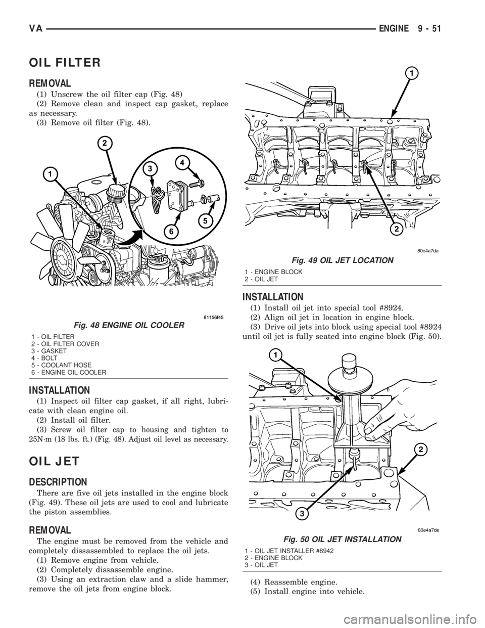
OIL FILTER
REMOVAL
(1) Unscrew the oil filter cap (Fig. 48)
(2) Remove clean and inspect cap gasket, replace
as necessary.
(3) Remove oil filter (Fig. 48).
INSTALLATION
(1) Inspect oil filter cap gasket, if all right, lubri-
cate with clean engine oil.
(2) Install oil filter.
(3)
Screw oil filter cap to housing and tighten to
25N´m (18 lbs. ft.) (Fig. 48). Adjust oil level as necessary.
OIL JET
DESCRIPTION
There are five oil jets installed in the engine block
(Fig. 49). These oil jets are used to cool and lubricate
the piston assemblies.
REMOVAL
The engine must be removed from the vehicle and
completely dissassembled to replace the oil jets.
(1) Remove engine from vehicle.
(2) Completely dissassemble engine.
(3) Using an extraction claw and a slide hammer,
remove the oil jets from engine block.
INSTALLATION
(1) Install oil jet into special tool #8924.
(2) Align oil jet in location in engine block.
(3) Drive oil jets into block using special tool #8924
until oil jet is fully seated into engine block (Fig. 50).
(4) Reassemble engine.
(5) Install engine into vehicle.
Fig. 48 ENGINE OIL COOLER
1 - OIL FILTER
2 - OIL FILTER COVER
3 - GASKET
4 - BOLT
5 - COOLANT HOSE
6 - ENGINE OIL COOLER
Fig. 49 OIL JET LOCATION
1 - ENGINE BLOCK
2 - OIL JET
Fig. 50 OIL JET INSTALLATION
1 - OIL JET INSTALLER #8942
2 - ENGINE BLOCK
3 - OIL JET
VAENGINE 9 - 51
Page 790 of 1232
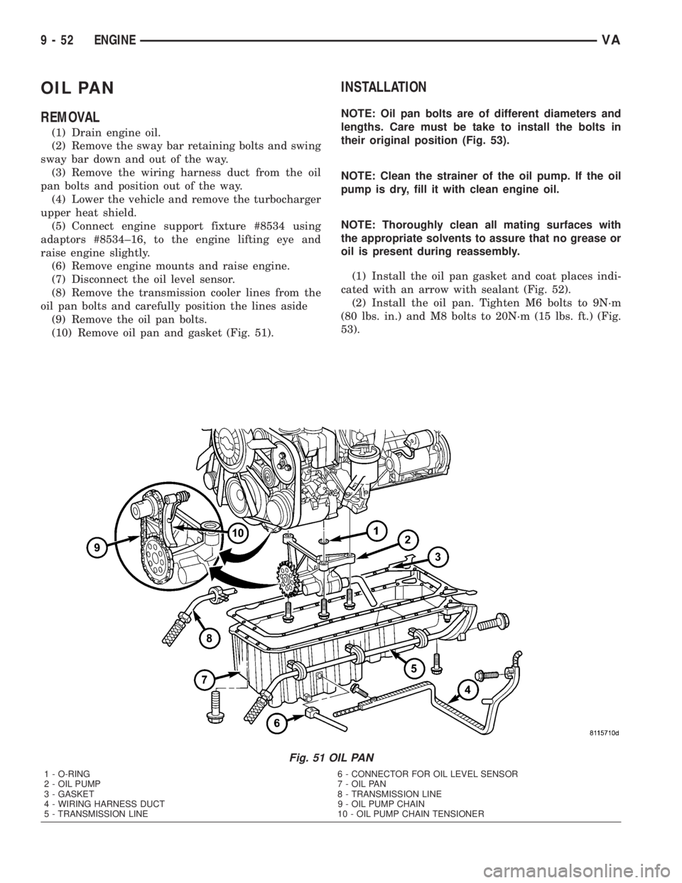
OIL PAN
REMOVAL
(1) Drain engine oil.
(2) Remove the sway bar retaining bolts and swing
sway bar down and out of the way.
(3) Remove the wiring harness duct from the oil
pan bolts and position out of the way.
(4) Lower the vehicle and remove the turbocharger
upper heat shield.
(5) Connect engine support fixture #8534 using
adaptors #8534±16, to the engine lifting eye and
raise engine slightly.
(6) Remove engine mounts and raise engine.
(7) Disconnect the oil level sensor.
(8) Remove the transmission cooler lines from the
oil pan bolts and carefully position the lines aside
(9) Remove the oil pan bolts.
(10) Remove oil pan and gasket (Fig. 51).
INSTALLATION
NOTE: Oil pan bolts are of different diameters and
lengths. Care must be take to install the bolts in
their original position (Fig. 53).
NOTE: Clean the strainer of the oil pump. If the oil
pump is dry, fill it with clean engine oil.
NOTE: Thoroughly clean all mating surfaces with
the appropriate solvents to assure that no grease or
oil is present during reassembly.
(1) Install the oil pan gasket and coat places indi-
cated with an arrow with sealant (Fig. 52).
(2) Install the oil pan. Tighten M6 bolts to 9N´m
(80 lbs. in.) and M8 bolts to 20N´m (15 lbs. ft.) (Fig.
53).
Fig. 51 OIL PAN
1 - O-RING 6 - CONNECTOR FOR OIL LEVEL SENSOR
2 - OIL PUMP 7 - OIL PAN
3 - GASKET 8 - TRANSMISSION LINE
4 - WIRING HARNESS DUCT 9 - OIL PUMP CHAIN
5 - TRANSMISSION LINE 10 - OIL PUMP CHAIN TENSIONER
9 - 52 ENGINEVA