MERCEDES-BENZ SPRINTER 2005 Service Repair Manual
Manufacturer: MERCEDES-BENZ, Model Year: 2005, Model line: SPRINTER, Model: MERCEDES-BENZ SPRINTER 2005Pages: 1232, PDF Size: 39.23 MB
Page 821 of 1232
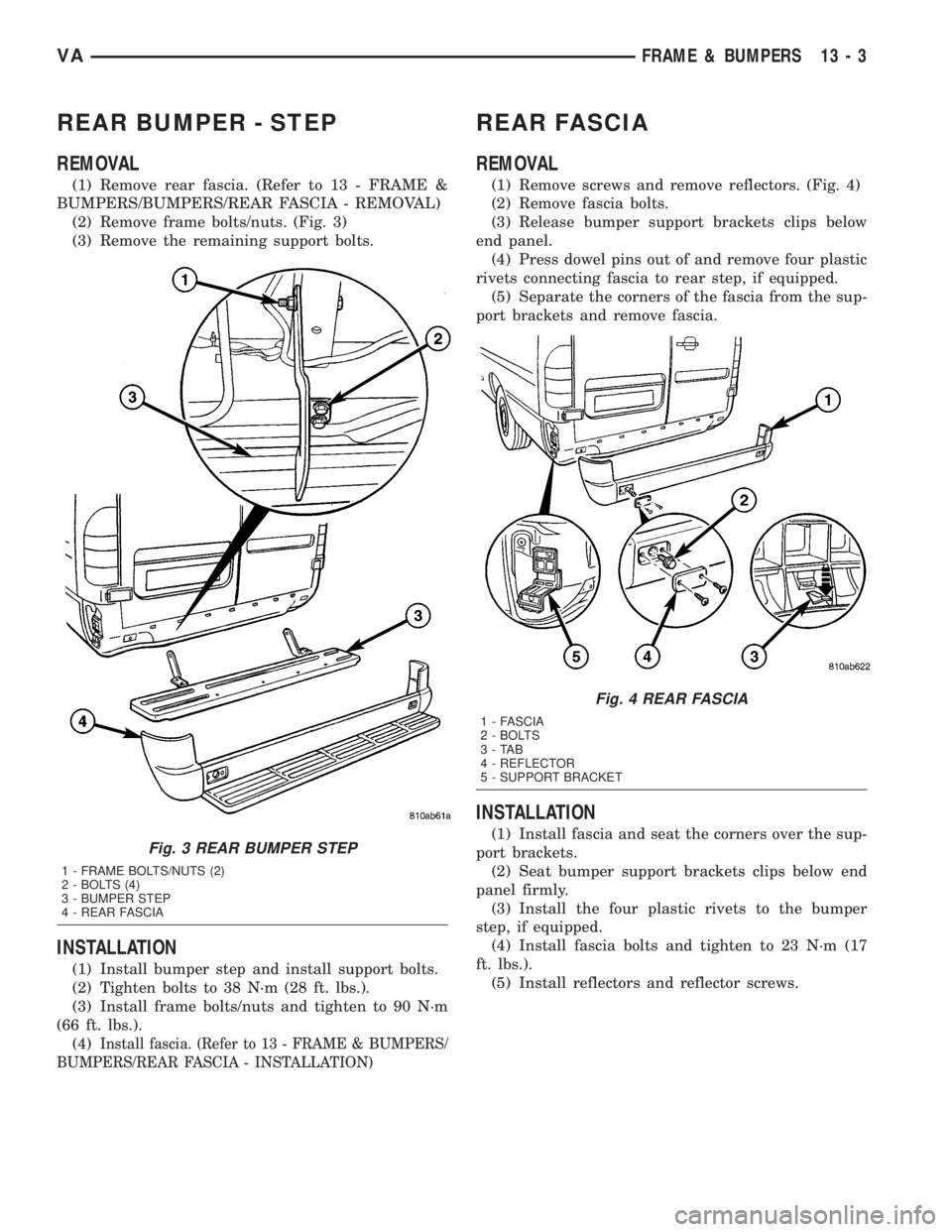
REAR BUMPER - STEP
REMOVAL
(1) Remove rear fascia. (Refer to 13 - FRAME &
BUMPERS/BUMPERS/REAR FASCIA - REMOVAL)
(2) Remove frame bolts/nuts. (Fig. 3)
(3) Remove the remaining support bolts.
INSTALLATION
(1) Install bumper step and install support bolts.
(2) Tighten bolts to 38 N´m (28 ft. lbs.).
(3) Install frame bolts/nuts and tighten to 90 N´m
(66 ft. lbs.).
(4)
Install fascia. (Refer to 13 - FRAME & BUMPERS/
BUMPERS/REAR FASCIA - INSTALLATION)
REAR FASCIA
REMOVAL
(1) Remove screws and remove reflectors. (Fig. 4)
(2) Remove fascia bolts.
(3) Release bumper support brackets clips below
end panel.
(4) Press dowel pins out of and remove four plastic
rivets connecting fascia to rear step, if equipped.
(5) Separate the corners of the fascia from the sup-
port brackets and remove fascia.
INSTALLATION
(1) Install fascia and seat the corners over the sup-
port brackets.
(2) Seat bumper support brackets clips below end
panel firmly.
(3) Install the four plastic rivets to the bumper
step, if equipped.
(4) Install fascia bolts and tighten to 23 N´m (17
ft. lbs.).
(5) Install reflectors and reflector screws.Fig. 3 REAR BUMPER STEP
1 - FRAME BOLTS/NUTS (2)
2 - BOLTS (4)
3 - BUMPER STEP
4 - REAR FASCIA
Fig. 4 REAR FASCIA
1 - FASCIA
2 - BOLTS
3-TAB
4 - REFLECTOR
5 - SUPPORT BRACKET
VAFRAME & BUMPERS 13 - 3
Page 822 of 1232
FRAME
SPECIFICATIONS
SPECIFICATIONS - FRAME DIMENSIONS
NOTE: Frame dimensions are listed in metric scale.
VEHICLE PREPARATION
Position the vehicle on a level work surface. Verti-
cal dimensions can be taken from the work surface to
the locations indicated were applicable.
INDEX
DESCRIPTION FIGURE
FRAME DIMENSIONS 5
13 - 4 FRAME & BUMPERSVA
Page 823 of 1232
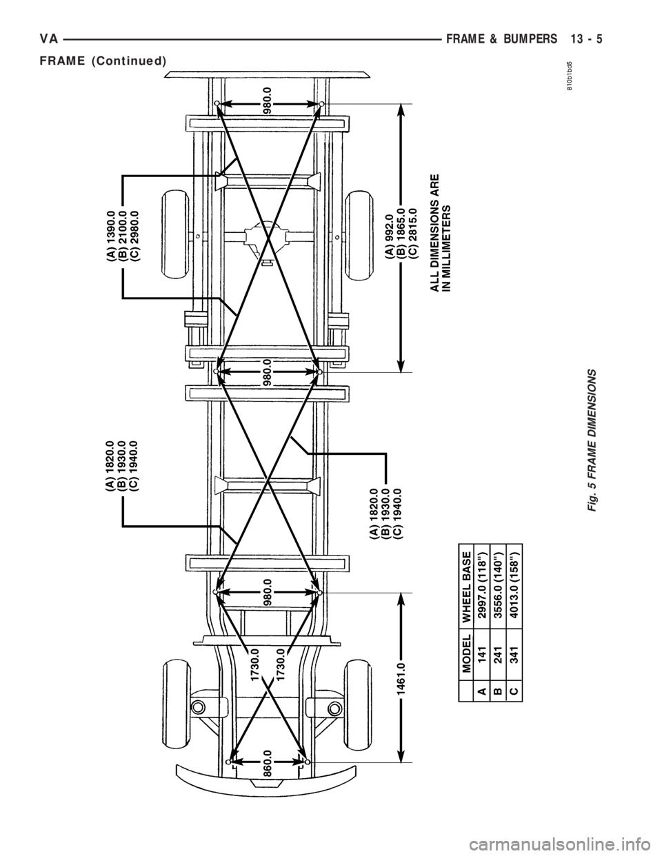
Fig. 5 FRAME DIMENSIONS
VAFRAME & BUMPERS 13 - 5
FRAME (Continued)
Page 824 of 1232
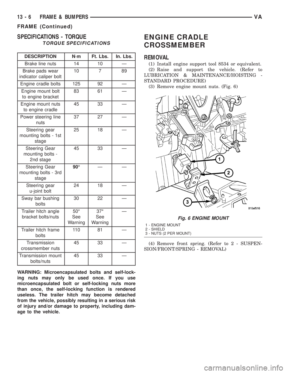
SPECIFICATIONS - TORQUE
TORQUE SPECIFICATIONS
DESCRIPTION N´m Ft. Lbs. In. Lbs.
Brake line nuts 14 10 Ð
Brake pads wear
indicator caliper bolt10 7 89
Engine cradle bolts 125 92 Ð
Engine mount bolt
to engine bracket83 61 Ð
Engine mount nuts
to engine cradle45 33 Ð
Power steering line
nuts37 27 Ð
Steering gear
mounting bolts - 1st
stage25 18 Ð
Steering Gear
mounting bolts -
2nd stage45 33 Ð
Steering Gear
mounting bolts - 3rd
stage90ÉÐÐ
Steering gear
u-joint bolt24 18 Ð
Sway bar bushing
bolts30 22 Ð
Trailer hitch angle
bracket bolts/nuts50*
See
Warning37*
See
WarningÐ
Trailer hitch frame
bolts11 0 8 1 Ð
Transmission
crossmember nuts45 33 Ð
Transmission mount
bolts/nuts45 33 Ð
WARNING: Microencapsulated bolts and self-lock-
ing nuts may only be used once. If you use
microencapsulated bolt or self-locking nuts more
than once, the self-locking function is rendered
useless. The trailer hitch may become detached
from the vehicle, possibly resulting in a serious risk
of injury and/or damage to property, including dam-
age to the vehicle.
ENGINE CRADLE
CROSSMEMBER
REMOVAL
(1) Install engine support tool 8534 or equivalent.
(2) Raise and support the vehicle. (Refer to
LUBRICATION & MAINTENANCE/HOISTING -
STANDARD PROCEDURE)
(3) Remove engine mount nuts. (Fig. 6)
(4) Remove front spring. (Refer to 2 - SUSPEN-
SION/FRONT/SPRING - REMOVAL)
Fig. 6 ENGINE MOUNT
1 - ENGINE MOUNT
2 - SHIELD
3 - NUTS (2 PER MOUNT)
13 - 6 FRAME & BUMPERSVA
FRAME (Continued)
Page 825 of 1232
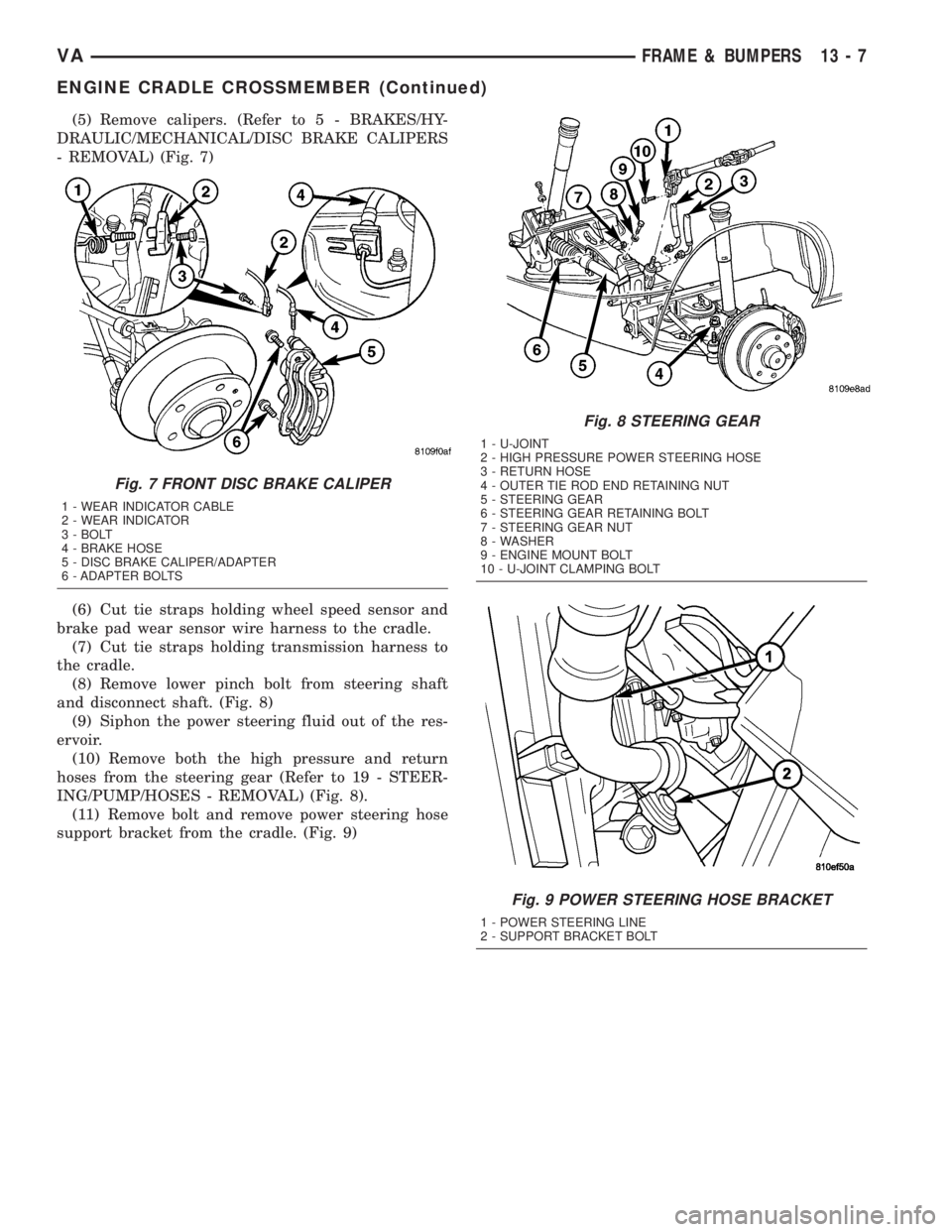
(5) Remove calipers. (Refer to 5 - BRAKES/HY-
DRAULIC/MECHANICAL/DISC BRAKE CALIPERS
- REMOVAL) (Fig. 7)
(6) Cut tie straps holding wheel speed sensor and
brake pad wear sensor wire harness to the cradle.
(7) Cut tie straps holding transmission harness to
the cradle.
(8) Remove lower pinch bolt from steering shaft
and disconnect shaft. (Fig. 8)
(9) Siphon the power steering fluid out of the res-
ervoir.
(10) Remove both the high pressure and return
hoses from the steering gear (Refer to 19 - STEER-
ING/PUMP/HOSES - REMOVAL) (Fig. 8).
(11) Remove bolt and remove power steering hose
support bracket from the cradle. (Fig. 9)
Fig. 7 FRONT DISC BRAKE CALIPER
1 - WEAR INDICATOR CABLE
2 - WEAR INDICATOR
3 - BOLT
4 - BRAKE HOSE
5 - DISC BRAKE CALIPER/ADAPTER
6 - ADAPTER BOLTS
Fig. 8 STEERING GEAR
1 - U-JOINT
2 - HIGH PRESSURE POWER STEERING HOSE
3 - RETURN HOSE
4 - OUTER TIE ROD END RETAINING NUT
5 - STEERING GEAR
6 - STEERING GEAR RETAINING BOLT
7 - STEERING GEAR NUT
8 - WASHER
9 - ENGINE MOUNT BOLT
10 - U-JOINT CLAMPING BOLT
Fig. 9 POWER STEERING HOSE BRACKET
1 - POWER STEERING LINE
2 - SUPPORT BRACKET BOLT
VAFRAME & BUMPERS 13 - 7
ENGINE CRADLE CROSSMEMBER (Continued)
Page 826 of 1232
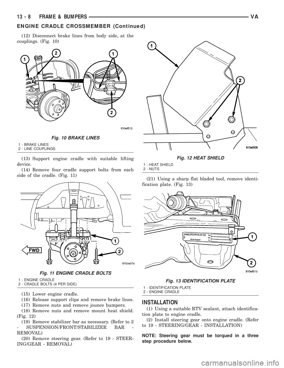
(12) Disconnect brake lines from body side, at the
couplings. (Fig. 10)
(13) Support engine cradle with suitable lifting
device.
(14) Remove four cradle support bolts from each
side of the cradle. (Fig. 11)
(15) Lower engine cradle.
(16) Release support clips and remove brake lines.
(17) Remove nuts and remove jounce bumpers.
(18) Remove nuts and remove mount heat shield.
(Fig. 12)
(19) Remove stabilizer bar as necessary. (Refer to 2
- SUSPENSION/FRONT/STABILIZER BAR -
REMOVAL)
(20) Remove steering gear. (Refer to 19 - STEER-
ING/GEAR - REMOVAL)(21) Using a sharp flat bladed tool, remove identi-
fication plate. (Fig. 13)
INSTALLATION
(1) Using a suitable RTV sealant, attach identifica-
tion plate to engine cradle.
(2) Install steering gear onto engine cradle. (Refer
to 19 - STEERING/GEAR - INSTALLATION)
NOTE: Steering gear must be torqued in a three
step procedure below.
Fig. 10 BRAKE LINES
1 - BRAKE LINES
2 - LINE COUPLINGS
Fig. 11 ENGINE CRADLE BOLTS
1 - ENGINE CRADLE
2 - CRADLE BOLTS (4 PER SIDE)
Fig. 12 HEAT SHIELD
1 - HEAT SHIELD
2 - NUTS
Fig. 13 IDENTIFICATION PLATE
1 - IDENTIFICATION PLATE
2 - ENGINE CRADLE
13 - 8 FRAME & BUMPERSVA
ENGINE CRADLE CROSSMEMBER (Continued)
Page 827 of 1232
(3) Tighten steering gear bolts in three stages as
follows.
1. Tighten to 25 N´m (18 ft. lbs.)
2. Then tighten to 45 N´m (33 ft. lbs.)
3. Then tighten bolts an additional 90É.
(4) Install stabilizer bar. (Refer to 2 - SUSPEN-
SION/FRONT/STABILIZER BAR - INSTALLATION)
(5) Install heat shield and nuts.
(6) Install jounce bumpers and install nuts.
(7) Install support clips and brake lines.
(8) Raise engine cradle into place and install bolts.
(9) Tighten bolts to 125 N´m (92 ft. lbs.).
(10) Connect brake lines at couplings and tighten
to 14 N´m (10 ft. lbs.).
(11) Position power steering hose and install sup-
port bracket bolt.
(12) Install both power steering hoses at steering
gear. (Refer to 19 - STEERING/PUMP/HOSES -
INSTALLATION)
(13) Connect steering shaft to gear and install the
lower pinch bolt.
(14) Tighten lower pinch bolt to 24 N´m (18 ft.
lbs.).
(15) Install new tie straps holding transmission
harness to cradle.
(16) Install front spring. (Refer to 2 - SUSPEN-
SION/FRONT/SPRING - INSTALLATION)
(17) Install engine mount nuts and tighten to 45
N´m (33 ft. lbs.).
(18) Install calipers. (Refer to 5 - BRAKES/HY-
DRAULIC/MECHANICAL/DISC BRAKE CALIPERS
- INSTALLATION)
(19) Install new tie straps holding wheel speed
sensors and brake pad wear sensors wire harness to
cradle.
(20) Check and align vehicle to specifications.
(Refer to 2 - SUSPENSION/WHEEL ALIGNMENT -
STANDARD PROCEDURE)
REAR CROSSMEMBER -
TRANSMISSION
REMOVAL
(1) Raise and support the vehicle. (Refer to
LUBRICATION & MAINTENANCE/HOISTING -
STANDARD PROCEDURE)
(2) Support transmission with a suitable lifting
device.
(3) Remove the bolts/nuts and remove transmis-
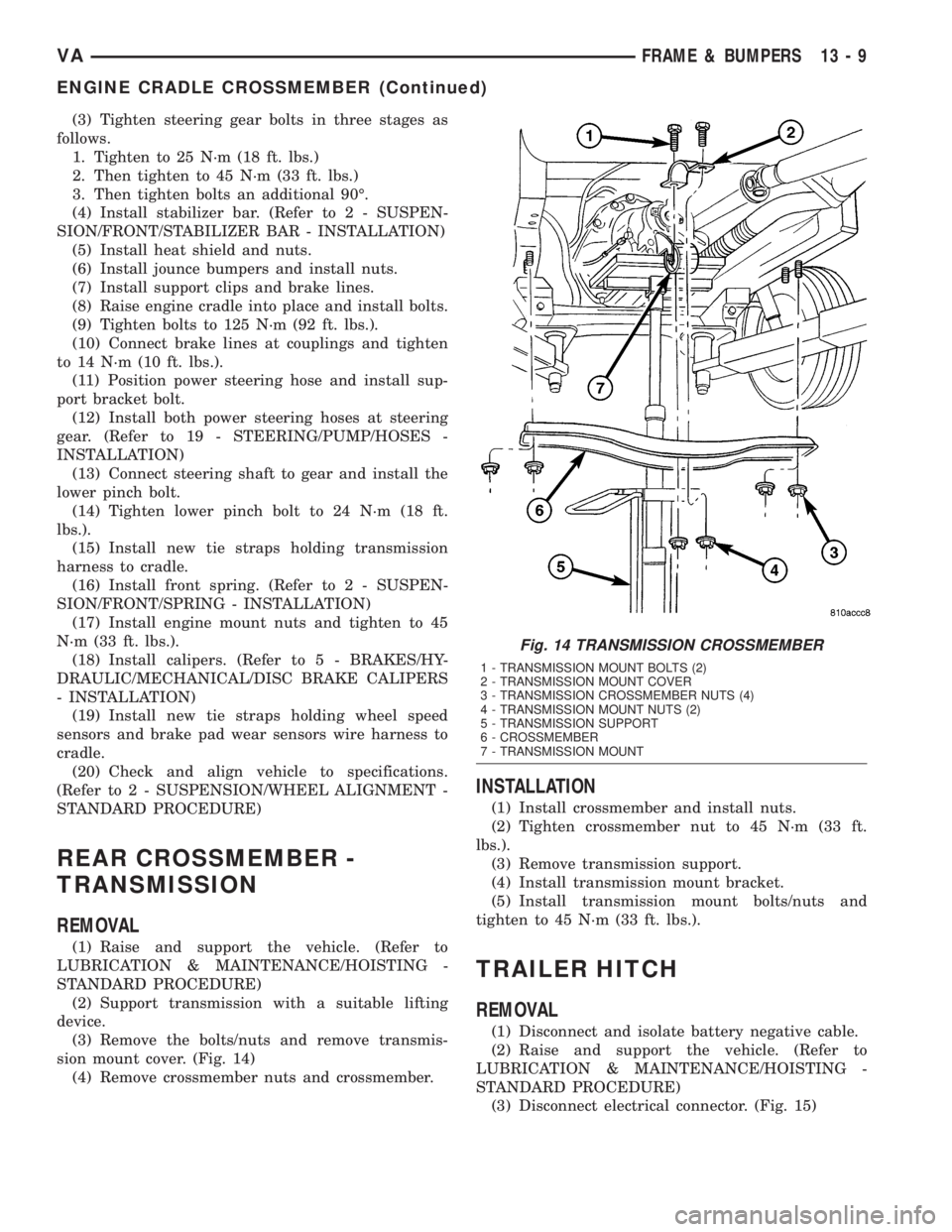
sion mount cover. (Fig. 14)
(4) Remove crossmember nuts and crossmember.
INSTALLATION
(1) Install crossmember and install nuts.
(2) Tighten crossmember nut to 45 N´m (33 ft.
lbs.).
(3) Remove transmission support.
(4) Install transmission mount bracket.
(5) Install transmission mount bolts/nuts and
tighten to 45 N´m (33 ft. lbs.).
TRAILER HITCH
REMOVAL
(1) Disconnect and isolate battery negative cable.
(2) Raise and support the vehicle. (Refer to
LUBRICATION & MAINTENANCE/HOISTING -
STANDARD PROCEDURE)
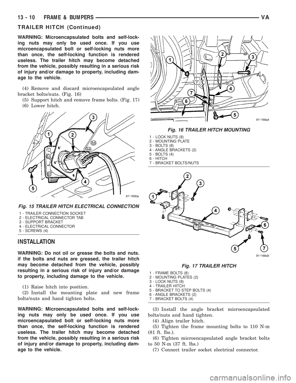
(3) Disconnect electrical connector. (Fig. 15)
Fig. 14 TRANSMISSION CROSSMEMBER
1 - TRANSMISSION MOUNT BOLTS (2)
2 - TRANSMISSION MOUNT COVER
3 - TRANSMISSION CROSSMEMBER NUTS (4)
4 - TRANSMISSION MOUNT NUTS (2)
5 - TRANSMISSION SUPPORT
6 - CROSSMEMBER
7 - TRANSMISSION MOUNT
VAFRAME & BUMPERS 13 - 9
ENGINE CRADLE CROSSMEMBER (Continued)
Page 828 of 1232
WARNING: Microencapsulated bolts and self-lock-
ing nuts may only be used once. If you use
microencapsulated bolt or self-locking nuts more
than once, the self-locking function is rendered
useless. The trailer hitch may become detached
from the vehicle, possibly resulting in a serious risk
of injury and/or damage to property, including dam-
age to the vehicle.
(4) Remove and discard microencapsulated angle
bracket bolts/nuts. (Fig. 16)
(5) Support hitch and remove frame bolts. (Fig. 17)
(6) Lower hitch.
INSTALLATION
WARNING: Do not oil or grease the bolts and nuts.
if the bolts and nuts are greased, the trailer hitch
may become detached from the vehicle, possibly
resulting in a serious risk of injury and/or damage
to property, including damage to the vehicle.
(1) Raise hitch into position.
(2) Install the mounting plate and new frame
bolts/nuts and hand tighten bolts.
WARNING: Microencapsulated bolts and self-lock-
ing nuts may only be used once. If you use
microencapsulated bolt or self-locking nuts more
than once, the self-locking function is rendered
useless. The trailer hitch may become detached
from the vehicle, possibly resulting in a serious risk
of injury and/or damage to property, including dam-
age to the vehicle.(3) Install the angle bracket microencapsulated
bolts/nuts and hand tighten.
(4) Align trailer hitch.
(5) Tighten the frame mounting bolts to 110 N´m
(81 ft. lbs.).
(6) Tighten microencapsulated angle bracket bolts
to 50 N´m (37 ft. lbs.)
(7) Connect trailer socket electrical connector.
Fig. 15 TRAILER HITCH ELECTRICAL CONNECTION
1 - TRAILER CONNECTION SOCKET
2 - ELECTRICAL CONNECTOR TAB
3 - SUPPORT BRACKET
4 - ELECTRICAL CONNECTOR
5 - SCREWS (4)
Fig. 16 TRAILER HITCH MOUNTING
1 - LOCK NUTS (8)
2 - MOUNTING PLATE
3 - BOLTS (8)
4 - ANGLE BRACKETS (2)
5 - BOLTS (4)
6 - HITCH
7 - BRACKET BOLTS/NUTS
Fig. 17 TRAILER HITCH
1 - FRAME BOLTS (8)
2 - MOUNTING PLATES (2)
3 - LOCK NUTS (8)
4 - TRAILER HITCH
5 - BRACKET TO STEP BOLTS (4)
6 - ANGLE BRACKETS (2)
7 - BRACKET BOLTS (4)
13 - 10 FRAME & BUMPERSVA
TRAILER HITCH (Continued)
Page 829 of 1232
FUEL SYSTEM
TABLE OF CONTENTS
page page
FUEL SYSTEM
WARNING
WARNING - HIGH FUEL SYSTEM
PRESSURE...........................1
WARNING............................1
DIAGNOSIS AND TESTING
DIAGNOSIS AND TESTING - HIGH
PRESSURE FUEL LINES.................1
DIAGNOSIS AND TESTING - AIR IN FUEL
SYSTEM.............................2
STANDARD PROCEDURE
STANDARD PROCEDURES - CLEANING
FUEL SYSTEM COMPONENTS............2STANDARD PROCEDURE -
DISCONNECTING AND CONNECTING
FUEL LINES..........................2
STANDARD PROCEDURES - DRAINING
WATER FROM FUEL FILTER..............2
STANDARD PROCEDURE - LOW
PRESSURE FUEL PUMP TEST............3
FUEL DELIVERY..........................4
FUEL INJECTION........................17
FUEL SYSTEM
WARNING
WARNING - HIGH FUEL SYSTEM PRESSURE
WARNING: HIGH-PRESSURE FUEL LINES DELIVER
FUEL UNDER EXTREME PRESSURE FROM THE
INJECTION PUMP TO THE INJECTORS. THIS
MAYBE AS HIGH AS 1600BAR (23,200PSI). USE
EXTREME CAUTION WHEN INSPECTING FOR HIGH-
PRESSURE FUEL LEAKS. FUEL UNDER THIS
AMOUNT OF PRESSURE CAN PENETRATE SKIN
CAUSING PERSONAL INJURY OR DEATH. INSPECT
HIGH-PRESSURE FUEL LEAKS WITH A SHEET OF
CARDBOARD. WEAR SAFETY GOGGLES AND ADE-
QUATE PROTECTIVE CLOTHING WHEN SERVICING
FUEL SYSTEM.
WARNING
WARNING: UNDER NO CIRCUMSTANCES SHOULD
GASOLINE BE MIXED WITH DIESEL FUEL (NOT
EVEN DURING WINTER). THE HIGH PRESSURE
PUMP IS LUBRICATED BY DIESEL FUEL. IMMEDI-
ATE FUEL SYSTEM DAMAGE MAY OCCUR CAUS-
ING REPLACEMENT AND FLUSHING OF THE
COMPLETE DIESEL FUEL SYSTEM. HIGH PRES-
SURE PUMP SEIZURE WILL CAUSE METAL PARTI-
CLES TO SPREAD THROUGH OUT THE FUEL
CIRCUIT. ALL CDI FUEL SYSTEM COMPONENTS
CONNECTED TO THE FUEL CIRCUIT WILL HAVE TO
BE EXCHANGED AND THE LINES FLUSHED.
DIAGNOSIS AND TESTING
DIAGNOSIS AND TESTING - HIGH PRESSURE
FUEL LINES
(Refer to 14 - FUEL SYSTEM - WARNING). High-
pressure fuel line leaks can cause starting problems
and poor engine performance.
WARNING: DUE TO EXTREME FUEL PRESSURES,
USE EXTREME CAUTION WHEN INSPECTING FOR
HIGH-PRESSURE FUEL LEAKS. DO NOT GET YOUR
HAND NEAR A SUSPECTED LEAK. INSPECT FOR
HIGH-PRESSURE FUEL LEAKS WITH A SHEET OF
CARDBOARD. HIGH FUEL INJECTION PRESSURE
CAN CAUSE PERSONAL INJURY IF CONTACT IS
MADE WITH THE SKIN.
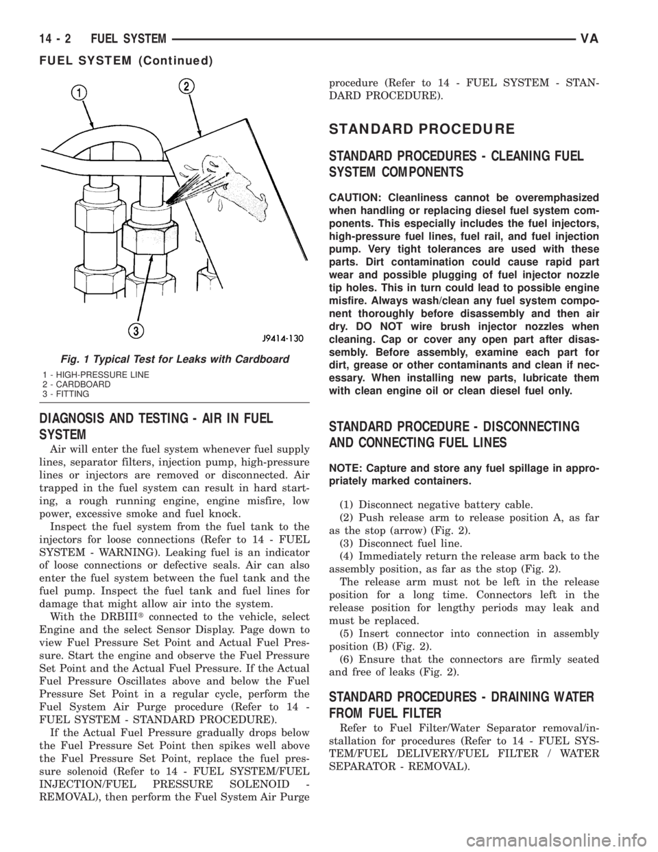
Start the engine. Move the cardboard over the
high-pressure fuel lines and check for fuel spray onto
the cardboard (Fig. 1). If a high-pressure line connec-
tion is leaking, tighten the connection and perform
the Fuel System Air Purge procedure (Refer to 14 -
FUEL SYSTEM - STANDARD PROCEDURE).
Replace damaged, restricted or leaking high-pressure
fuel lines with the correct replacement line.
CAUTION: The high-pressure fuel lines cannot con-
tact each other or other components. Do not
attempt to weld high-pressure fuel lines or to repair
lines that are damaged. Only use the recommended
lines when replacement of high-pressure fuel line is
necessary.
VAFUEL SYSTEM 14 - 1
Page 830 of 1232
DIAGNOSIS AND TESTING - AIR IN FUEL
SYSTEM
Air will enter the fuel system whenever fuel supply
lines, separator filters, injection pump, high-pressure
lines or injectors are removed or disconnected. Air
trapped in the fuel system can result in hard start-
ing, a rough running engine, engine misfire, low
power, excessive smoke and fuel knock.
Inspect the fuel system from the fuel tank to the
injectors for loose connections (Refer to 14 - FUEL
SYSTEM - WARNING). Leaking fuel is an indicator
of loose connections or defective seals. Air can also
enter the fuel system between the fuel tank and the
fuel pump. Inspect the fuel tank and fuel lines for
damage that might allow air into the system.
With the DRBIIItconnected to the vehicle, select
Engine and the select Sensor Display. Page down to
view Fuel Pressure Set Point and Actual Fuel Pres-
sure. Start the engine and observe the Fuel Pressure
Set Point and the Actual Fuel Pressure. If the Actual
Fuel Pressure Oscillates above and below the Fuel
Pressure Set Point in a regular cycle, perform the
Fuel System Air Purge procedure (Refer to 14 -
FUEL SYSTEM - STANDARD PROCEDURE).
If the Actual Fuel Pressure gradually drops below
the Fuel Pressure Set Point then spikes well above
the Fuel Pressure Set Point, replace the fuel pres-
sure solenoid (Refer to 14 - FUEL SYSTEM/FUEL
INJECTION/FUEL PRESSURE SOLENOID -
REMOVAL), then perform the Fuel System Air Purgeprocedure (Refer to 14 - FUEL SYSTEM - STAN-
DARD PROCEDURE).
STANDARD PROCEDURE
STANDARD PROCEDURES - CLEANING FUEL
SYSTEM COMPONENTS
CAUTION: Cleanliness cannot be overemphasized
when handling or replacing diesel fuel system com-
ponents. This especially includes the fuel injectors,
high-pressure fuel lines, fuel rail, and fuel injection
pump. Very tight tolerances are used with these
parts. Dirt contamination could cause rapid part
wear and possible plugging of fuel injector nozzle
tip holes. This in turn could lead to possible engine
misfire. Always wash/clean any fuel system compo-
nent thoroughly before disassembly and then air
dry. DO NOT wire brush injector nozzles when
cleaning. Cap or cover any open part after disas-
sembly. Before assembly, examine each part for
dirt, grease or other contaminants and clean if nec-
essary. When installing new parts, lubricate them
with clean engine oil or clean diesel fuel only.
STANDARD PROCEDURE - DISCONNECTING
AND CONNECTING FUEL LINES
NOTE: Capture and store any fuel spillage in appro-
priately marked containers.
(1) Disconnect negative battery cable.
(2) Push release arm to release position A, as far
as the stop (arrow) (Fig. 2).
(3) Disconnect fuel line.
(4) Immediately return the release arm back to the
assembly position, as far as the stop (Fig. 2).
The release arm must not be left in the release
position for a long time. Connectors left in the
release position for lengthy periods may leak and
must be replaced.
(5) Insert connector into connection in assembly
position (B) (Fig. 2).
(6) Ensure that the connectors are firmly seated
and free of leaks (Fig. 2).
STANDARD PROCEDURES - DRAINING WATER
FROM FUEL FILTER
Refer to Fuel Filter/Water Separator removal/in-
stallation for procedures (Refer to 14 - FUEL SYS-
TEM/FUEL DELIVERY/FUEL FILTER / WATER
SEPARATOR - REMOVAL).
Fig. 1 Typical Test for Leaks with Cardboard
1 - HIGH-PRESSURE LINE
2 - CARDBOARD
3 - FITTING
14 - 2 FUEL SYSTEMVA
FUEL SYSTEM (Continued)