MERCEDES-BENZ SPRINTER 2005 Service Repair Manual
Manufacturer: MERCEDES-BENZ, Model Year: 2005, Model line: SPRINTER, Model: MERCEDES-BENZ SPRINTER 2005Pages: 1232, PDF Size: 39.23 MB
Page 811 of 1232
EXHAUST SYSTEM
TABLE OF CONTENTS
page page
EXHAUST SYSTEM
DESCRIPTION - 2.7L DIESEL...............1
DIAGNOSIS AND TESTING - DIESEL ENGINE . . 2
CATALYTIC CONVERTER
REMOVAL.............................3
INSTALLATION..........................3
EXHAUST PIPE
REMOVAL.............................3
INSTALLATION..........................3
TAILPIPE
REMOVAL.............................3
INSTALLATION..........................3
TURBOCHARGER SYSTEM
DESCRIPTION..........................3
OPERATION............................4
CHARGE AIR COOLER AND PLUMBING
DESCRIPTION..........................4OPERATION............................4
DIAGNOSIS AND TESTING - CHARGE AIR
COOLER SYSTEM - LEAKS...............4
REMOVAL.............................5
CLEANING.............................5
INSPECTION...........................5
INSTALLATION..........................5
TURBOCHARGER
DESCRIPTION..........................6
OPERATION............................6
REMOVAL
REMOVAL............................7
REMOVAL - VACUUM TRANSDUCER.......7
INSTALLATION
INSTALLATION........................8
INSTALLATION - VACUUM TRANSDUCER . . . 8
EXHAUST SYSTEM
DESCRIPTION - 2.7L DIESEL
CAUTION: Avoid application of rust prevention com-
pounds or undercoating materials to exhaust sys-
tem floor pan exhaust heat shields. Light overspray
near the edges is permitted. Application of coating
will result in excessive floor pan temperatures and
objectionable fumes.
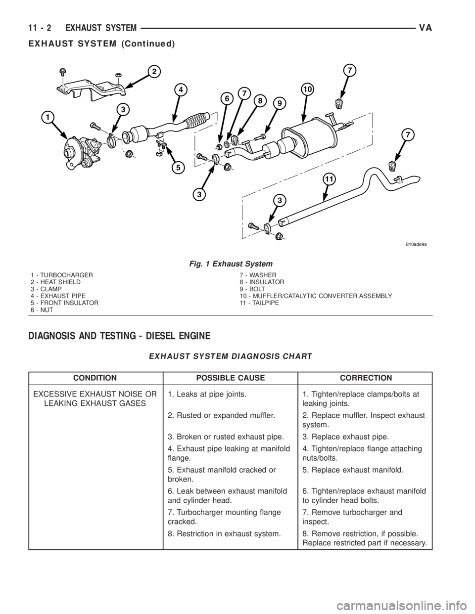
The diesel engine exhaust system consists of an
engine exhaust manifold, turbocharger, exhaust pipe,
resonator, extension pipe (if needed), muffler and
exhaust tailpipe (Fig. 1).The exhaust system must be properly aligned and
secured to prevent stress, leakage and body contact.
The exhaust components should be kept a minimum
of 25.4 mm (1.0 in.) away from the body and frame.
If the system contacts any body panel, it may amplify
objectionable noises from the engine or body.
VAEXHAUST SYSTEM 11 - 1
Page 812 of 1232
DIAGNOSIS AND TESTING - DIESEL ENGINE
EXHAUST SYSTEM DIAGNOSIS CHART
CONDITION POSSIBLE CAUSE CORRECTION
EXCESSIVE EXHAUST NOISE OR
LEAKING EXHAUST GASES1. Leaks at pipe joints. 1. Tighten/replace clamps/bolts at
leaking joints.
2. Rusted or expanded muffler. 2. Replace muffler. Inspect exhaust
system.
3. Broken or rusted exhaust pipe. 3. Replace exhaust pipe.
4. Exhaust pipe leaking at manifold
flange.4. Tighten/replace flange attaching
nuts/bolts.
5. Exhaust manifold cracked or
broken.5. Replace exhaust manifold.
6. Leak between exhaust manifold
and cylinder head.6. Tighten/replace exhaust manifold
to cylinder head bolts.
7. Turbocharger mounting flange
cracked.7. Remove turbocharger and
inspect.
8. Restriction in exhaust system. 8. Remove restriction, if possible.
Replace restricted part if necessary.
Fig. 1 Exhaust System
1 - TURBOCHARGER
2 - HEAT SHIELD
3 - CLAMP
4 - EXHAUST PIPE
5 - FRONT INSULATOR
6 - NUT7 - WASHER
8 - INSULATOR
9 - BOLT
10 - MUFFLER/CATALYTIC CONVERTER ASSEMBLY
11 - TAILPIPE
11 - 2 EXHAUST SYSTEMVA
EXHAUST SYSTEM (Continued)
Page 813 of 1232
CATALYTIC CONVERTER
REMOVAL
(1) Raise and support the vehicle.
(2) Saturate the clamp nuts with heat valve lubri-
cant. Allow 5 minutes for penetration. Remove the
rear clamp. (Fig. 1)
(3) Saturate the clamp nuts with heat valve lubri-
cant. Allow 5 minutes for penetration. Remove the
front clamp.
(4) Remove the cataylic converter and muffler
assembly from the isolators.
(5) Seperat the cataylic converter and muffler
assembly from the tailpipe and the exhaust pipe.
(6) Remove the cataylic converter and muffler
assembly and isolators from the vehicle.
(7) Remove the bolt, nut and front isolator from
the cataylic converter and muffler assembly.
(8) Remove the rear isolator from the cataylic con-
verter and muffler assembly.
(9)
INSTALLATION
(1) Install bolt, front isolator and nut (Fig. 1).
(2) Install rear insulator onto the cataylic con-
verter and muffler assembly
(3) Position the cataylic conveter and muffler
assembly into the exhaust pipe and tailpipe until
alignment tab is inserted into the alignment slot.
(4) Install the front and rear insulators.
(5) Install the real clamp.
(6) Install the front clamp.
(7) Lower vehicle.
(8) Start the vehicle and inspect for exhaust leaks.
Repair exhaust leaks as necessary.
(9) Check the exhaust system for contact with the
body panels. Make necessary adjustments, if neces-
sary.
EXHAUST PIPE
REMOVAL
(1) Raise and support the vehicle.
(2) Saturate the clamp nuts with heat valve lubri-
cant. Allow 5 minutes for penetration. Remove the
front and rear clamp (Fig. 1).
(3) Remove the mounting bracket nuts.
(4) Remove the exhaust pipe.
INSTALLATION
(1) Position the exhaust pipe into the exhaust pipe
into the cataylic converter and muffler assembly
until alignment tab is inserted into the alignment
slot.
(2) Install mounting bracket and nuts (Fig. 1).(3) Install clamp.
(4) Lower the vehicle.
(5) Start the vehicle and inspect for exhaust leaks.
Repair exhaust leaks as necessary.
(6) Check the exhaust system for contact with the
body panels. Make necessary adjustments, if neces-
sary.
TAILPIPE
REMOVAL
(1) Raise and support the vehicle.
(2) Saturate the clamp nuts with heat valve lubri-
cant. Allow 5 minutes for penetration (Fig. 1).
(3) Remove the clamp.
(4) Remove the tailpipe and insulator form the
vehicle
(5) Remove the insulator from the tailpipe.
INSTALLATION
(1) Position the tail pipe into the cataylic converter
and muffler assembly until alignment tab is inserted
into the alignment slot.
(2) Install the insulator.
(3) Install the clamp.
(4) Lower the vehicle.
(5) Start the vehicle and inspect for exhaust leaks.
Repair exhaust leaks as necessary.
(6) Check the exhaust system for contact with the
body panels. Make necessary adjustments, if neces-
sary.
TURBOCHARGER SYSTEM
DESCRIPTION
CAUTION: The turbocharger is a performance part
and must not be tampered with. The boost pressure
bracket is an integral part of the turbocharger. Tam-
pering with the boost pressure components can
reduce durability by increasing cylinder pressure
and thermal loading due to incorrect inlet and
exhaust manifold pressure. Poor fuel economy and
failure to meet regulatory emissions laws may
result. Increasing the turbocharger boost WILL NOT
increase engine power.
The turbocharger used on this vehicle is of the
variable turbine type. These turbochargers use the
entire exhaust energy to boost efficiency of the turbo-
charger and the engine.
The advantages of a turbocharger with variable
turbine geometry are:
²Higher charge pressure already in the lower and
in upper engine speed ranges.
VAEXHAUST SYSTEM 11 - 3
Page 814 of 1232
²Higher torque as a result of improved cylinder
charge.
²Reduction in exhaust emissions as a result of an
improvement in the air supply of the engine.
²Increased power output as a result of the higher
charge pressure combined with a reduced exhaust
backpressure and thus improved charge cycle.
OPERATION
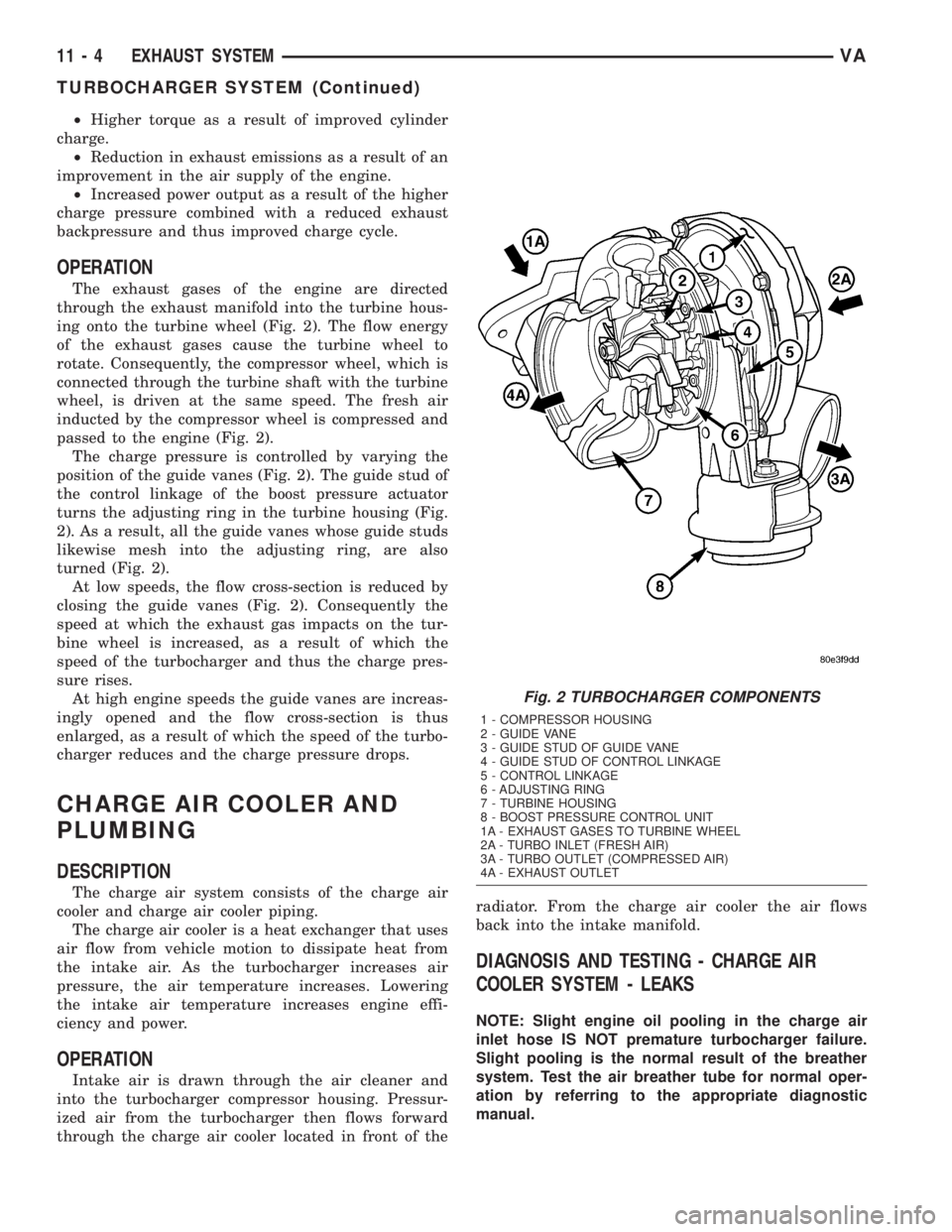
The exhaust gases of the engine are directed
through the exhaust manifold into the turbine hous-
ing onto the turbine wheel (Fig. 2). The flow energy
of the exhaust gases cause the turbine wheel to
rotate. Consequently, the compressor wheel, which is
connected through the turbine shaft with the turbine
wheel, is driven at the same speed. The fresh air
inducted by the compressor wheel is compressed and
passed to the engine (Fig. 2).
The charge pressure is controlled by varying the
position of the guide vanes (Fig. 2). The guide stud of
the control linkage of the boost pressure actuator
turns the adjusting ring in the turbine housing (Fig.
2). As a result, all the guide vanes whose guide studs
likewise mesh into the adjusting ring, are also
turned (Fig. 2).
At low speeds, the flow cross-section is reduced by
closing the guide vanes (Fig. 2). Consequently the
speed at which the exhaust gas impacts on the tur-
bine wheel is increased, as a result of which the
speed of the turbocharger and thus the charge pres-
sure rises.
At high engine speeds the guide vanes are increas-
ingly opened and the flow cross-section is thus
enlarged, as a result of which the speed of the turbo-
charger reduces and the charge pressure drops.
CHARGE AIR COOLER AND
PLUMBING
DESCRIPTION
The charge air system consists of the charge air
cooler and charge air cooler piping.
The charge air cooler is a heat exchanger that uses
air flow from vehicle motion to dissipate heat from
the intake air. As the turbocharger increases air
pressure, the air temperature increases. Lowering
the intake air temperature increases engine effi-
ciency and power.
OPERATION
Intake air is drawn through the air cleaner and
into the turbocharger compressor housing. Pressur-
ized air from the turbocharger then flows forward
through the charge air cooler located in front of theradiator. From the charge air cooler the air flows
back into the intake manifold.
DIAGNOSIS AND TESTING - CHARGE AIR
COOLER SYSTEM - LEAKS
NOTE: Slight engine oil pooling in the charge air
inlet hose IS NOT premature turbocharger failure.
Slight pooling is the normal result of the breather
system. Test the air breather tube for normal oper-
ation by referring to the appropriate diagnostic
manual.
Fig. 2 TURBOCHARGER COMPONENTS
1 - COMPRESSOR HOUSING
2 - GUIDE VANE
3 - GUIDE STUD OF GUIDE VANE
4 - GUIDE STUD OF CONTROL LINKAGE
5 - CONTROL LINKAGE
6 - ADJUSTING RING
7 - TURBINE HOUSING
8 - BOOST PRESSURE CONTROL UNIT
1A - EXHAUST GASES TO TURBINE WHEEL
2A - TURBO INLET (FRESH AIR)
3A - TURBO OUTLET (COMPRESSED AIR)
4A - EXHAUST OUTLET
11 - 4 EXHAUST SYSTEMVA
TURBOCHARGER SYSTEM (Continued)
Page 815 of 1232
Low turbocharger boost pressure and low engine
performance can be caused by leaks in the charge air
cooler or it's plumbing. The following procedure out-
lines how to check for leaks in the charge air cooler
system.
(1) Loosen clamp and remove turbocharger to air
inlet duct rubber sleeve from turbocharger.
(2) Insert Special Tool 8442 Adapter into the rub-
ber sleeve. Tighten existing clamp to 8 N´m (72
in.lbs.).
CAUTION: Do not apply more than 138 kpa (20 psi)
air pressure to the charge air cooler system, sever
damage to the charge air cooler system may occur.
(3) Connect regulated air supply to air fitting on
Special Tool 8442 Adapter. Set air pressure to a Max-
imum of 138 kpa (20 psi).
(4) Using soapy water check the air inlet ducts,
rubber sleeves, charge air cooler and intake manifold
for leaks.
REMOVAL
(1) Remove front bumper.
(2) Remove headlamp assemblies.
(3) Remove front cross member together with front
grille.
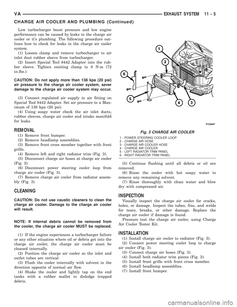
(4) Remove left and right radiator trim (Fig. 3).
(5) Disconnect charge air hoses at charge air cooler
(Fig. 3).
(6) Disconnect power steering cooler loop from
charge air cooler (Fig. 3).
(7) Remove charge air cooler from radiator assem-
bly (Fig. 3).
CLEANING
CAUTION: Do not use caustic cleaners to clean the
charge air cooler. Damage to the charge air cooler
will result.
NOTE: If internal debris cannot be removed from
the cooler, the charge air cooler MUST be replaced.
(1) If the engine experiences a turbocharger failure
or any other situation where oil or debris get into the
charge air cooler, the charge air cooler must be
cleaned internally.
(2) Position the charge air cooler so the inlet and
outlet tubes are vertical.
(3) Flush the cooler internally with solvent in the
direction opposite of normal air flow.
(4) Shake the cooler and lightly tap on the end
tanks with a rubber mallet to dislodge trapped
debris.(5) Continue flushing until all debris or oil are
removed.
(6) Rinse the cooler with hot soapy water to
remove any remaining solvent.
(7) Rinse thoroughly with clean water and blow
dry with compressed air.
INSPECTION
Visually inspect the charge air cooler for cracks,
holes, or damage. Inspect the tubes, fins, and welds
for tears, breaks, or other damage. Replace the
charge air cooler if damage is found.
Pressure test the charge air cooler, using Charge
Air Cooler Tester Kit.
INSTALLATION
(1) Install charge air cooler to radiator (Fig. 3).
(2) Connect power steering cooler loop to charge
air cooler (Fig. 3).
(3) Connect charge air hoses (Fig. 3).
(4) Install both radiator trim pieces (Fig. 3).
(5) Install front grille with front cross member.
(6) Install headlamp assemblies.
(7) Install front bumper.
Fig. 3 CHARGE AIR COOLER
1 - POWER STEERING COOLER LOOP
2 - CHARGE AIR HOSE
3 - CHARGE AIR COOLER HOSE
4 - CHARGE AIR COOLER
5 - LEFT RADIATOR TRIM PANEL
6 - RIGHT RADIATOR TRIM PANEL
VAEXHAUST SYSTEM 11 - 5
CHARGE AIR COOLER AND PLUMBING (Continued)
Page 816 of 1232
TURBOCHARGER
DESCRIPTION
The boost pressure vacuum solenoid is located
under the air filter housing and is responsible for
turbo-charger boost pressure. It generates a control
vacuum in response to a PWM signal from the ECM.
Vacuum is achieved by mixing the system vacuum
(from the vacuum pump) with atmospheric pressure
to a certain degree. The resulting vacuum is sent to
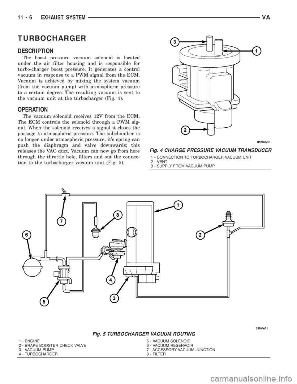
the vacuum unit at the turbocharger (Fig. 4).
OPERATION
The vacuum solenoid receives 12V from the ECM.
The ECM controls the solenoid through a PWM sig-
nal. When the solenoid receives a signal it closes the
passage to atmospheric pressure. The subchamber is
no longer under atmospheric pressure, it's spring can
push the diaphragm and valve downwards; this
releases the VAC duct. Vacuum can now go from here
through the throttle hole, filters and out the connec-
tion to the turbocharger vacuum unit (Fig. 5).
Fig. 4 CHARGE PRESSURE VACUUM TRANSDUCER
1 - CONNECTION TO TURBOCHARGER VACUUM UNIT
2 - VENT
3 - SUPPLY FROM VACUUM PUMP
Fig. 5 TURBOCHARGER VACUUM ROUTING
1 - ENGINE 5 - VACUUM SOLENOID
2 - BRAKE BOOSTER CHECK VALVE 6 - VACUUM RESERVOIR
3 - VACUUM PUMP 7 - ACCESSORY VACUUM JUNCTION
4 - TURBOCHARGER 8 - FILTER
11 - 6 EXHAUST SYSTEMVA
Page 817 of 1232
REMOVAL
REMOVAL
NOTE: Capture any fluid spillage and store in an
appropriately marked and suitable containers.
(1) Disconnect the negative battery cable.
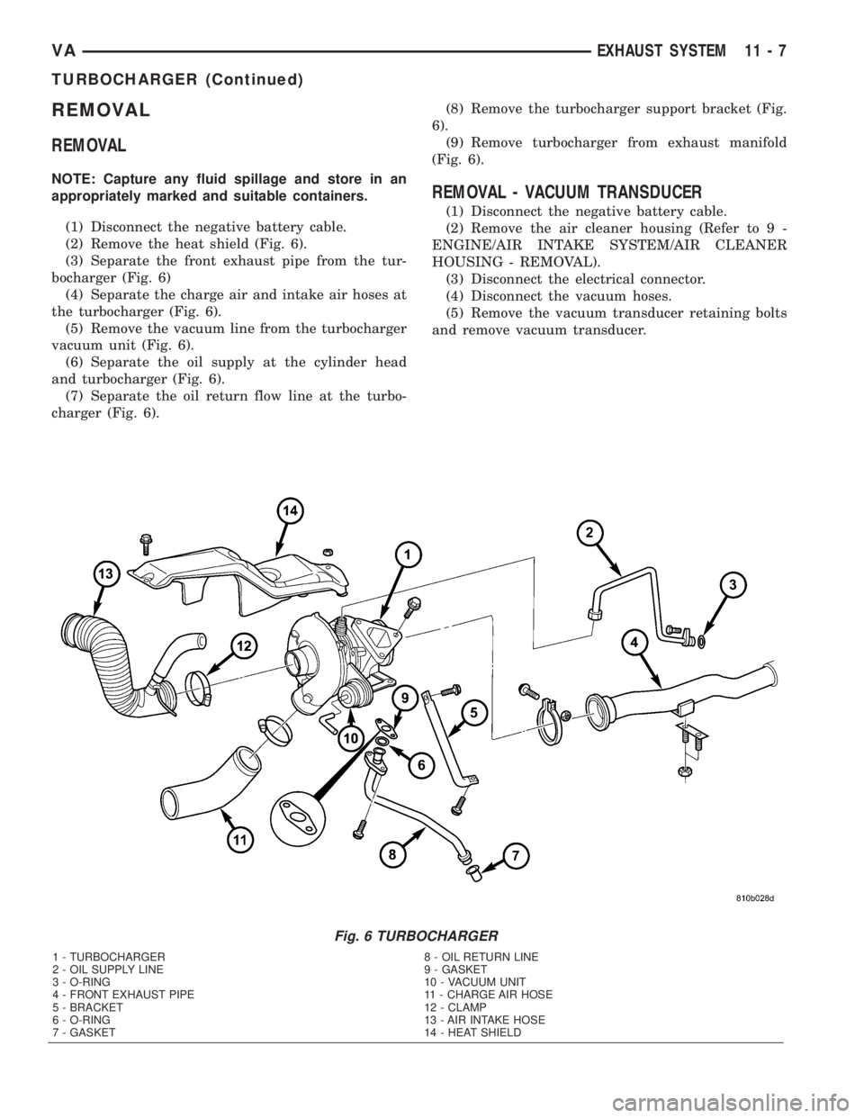
(2) Remove the heat shield (Fig. 6).
(3) Separate the front exhaust pipe from the tur-
bocharger (Fig. 6)
(4) Separate the charge air and intake air hoses at
the turbocharger (Fig. 6).
(5) Remove the vacuum line from the turbocharger
vacuum unit (Fig. 6).
(6) Separate the oil supply at the cylinder head
and turbocharger (Fig. 6).
(7) Separate the oil return flow line at the turbo-
charger (Fig. 6).(8) Remove the turbocharger support bracket (Fig.
6).
(9) Remove turbocharger from exhaust manifold
(Fig. 6).
REMOVAL - VACUUM TRANSDUCER
(1) Disconnect the negative battery cable.
(2) Remove the air cleaner housing (Refer to 9 -
ENGINE/AIR INTAKE SYSTEM/AIR CLEANER
HOUSING - REMOVAL).
(3) Disconnect the electrical connector.
(4) Disconnect the vacuum hoses.
(5) Remove the vacuum transducer retaining bolts
and remove vacuum transducer.
Fig. 6 TURBOCHARGER
1 - TURBOCHARGER 8 - OIL RETURN LINE
2 - OIL SUPPLY LINE 9 - GASKET
3 - O-RING 10 - VACUUM UNIT
4 - FRONT EXHAUST PIPE 11 - CHARGE AIR HOSE
5 - BRACKET 12 - CLAMP
6 - O-RING 13 - AIR INTAKE HOSE
7 - GASKET 14 - HEAT SHIELD
VAEXHAUST SYSTEM 11 - 7
TURBOCHARGER (Continued)
Page 818 of 1232
INSTALLATION
INSTALLATION
(1) Clean all mating surfaces
(2) Install turbocharger to exhaust manifold.
Tighten bolts to 22 lbs. ft. (20 N´m) (Fig. 6).
NOTE: Slacken the bottom bolt of the turbocharger
support bracket to install bracket stress free.
(3) Install turbocharger support bracket. Tighten
bolts to 177 lbs. in. (20 N´m) at engine and 22 lbs. ft.
(30 N´m) at turbocharger (Fig. 6).
(4) Replace gaskets and install oil return line at
turbocharger. Tighten bolt to 80 lbs. in. (9 N´m) (Fig.
6).
NOTE: Counterhold the connection at the turbo-
charger when tightening the oil supply line bolt.
(5) Replace gaskets and install oil supply line at
turbocharger. Tighten bolt to 160 lbs. in. (18 N´m)
(Fig. 6).(6) Attach turbocharger vacuum line to vacuum
unit (Fig. 6).
(7) Attach air intake and charge air hoses (Fig. 6).
(8) Connect front exhaust pipe to turbocharger.
Tighten flange clamp to 22 lbs.ft. (30 N´m) (Fig. 6).
(9) Install heat shield (Fig. 6).
(10) Connect negative battery cable.
INSTALLATION - VACUUM TRANSDUCER
(1) Position vacuum transducer and install the
retaining bolts. Tighten bolts to 70 lbs.in (8 N´m).
(2) Connect vacuum hoses.
(3) Connect electrical connector
(4) Install air cleaner housing (Refer to 9 -
ENGINE/AIR INTAKE SYSTEM/AIR CLEANER
HOUSING - INSTALLATION)
(5) Connect negative battery cable.
11 - 8 EXHAUST SYSTEMVA
TURBOCHARGER (Continued)
Page 819 of 1232
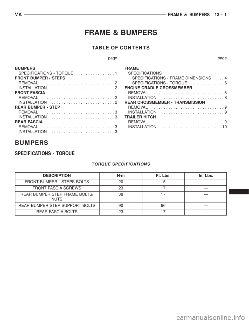
FRAME & BUMPERS
TABLE OF CONTENTS
page page
BUMPERS
SPECIFICATIONS - TORQUE...............1
FRONT BUMPER - STEPS
REMOVAL.............................2
INSTALLATION..........................2
FRONT FASCIA
REMOVAL.............................2
INSTALLATION..........................2
REAR BUMPER - STEP
REMOVAL.............................3
INSTALLATION..........................3
REAR FASCIA
REMOVAL.............................3
INSTALLATION..........................3FRAME
SPECIFICATIONS
SPECIFICATIONS - FRAME DIMENSIONS . . . 4
SPECIFICATIONS - TORQUE.............6
ENGINE CRADLE CROSSMEMBER
REMOVAL.............................6
INSTALLATION..........................8
REAR CROSSMEMBER - TRANSMISSION
REMOVAL.............................9
INSTALLATION..........................9
TRAILER HITCH
REMOVAL.............................9
INSTALLATION.........................10
BUMPERS
SPECIFICATIONS - TORQUE
TORQUE SPECIFICATIONS
DESCRIPTION N´m Ft. Lbs. In. Lbs.
FRONT BUMPER - STEPS BOLTS 20 15 Ð
FRONT FASCIA SCREWS 23 17 Ð
REAR BUMPER STEP FRAME BOLTS/
NUTS38 17 Ð
REAR BUMPER STEP SUPPORT BOLTS 90 66 Ð
REAR FASCIA BOLTS 23 17 Ð
VAFRAME & BUMPERS 13 - 1
Page 820 of 1232
FRONT BUMPER - STEPS
REMOVAL
(1) Remove fascia. (Refer to 13 - FRAME &
BUMPERS/BUMPERS/FRONT FASCIA -
REMOVAL)
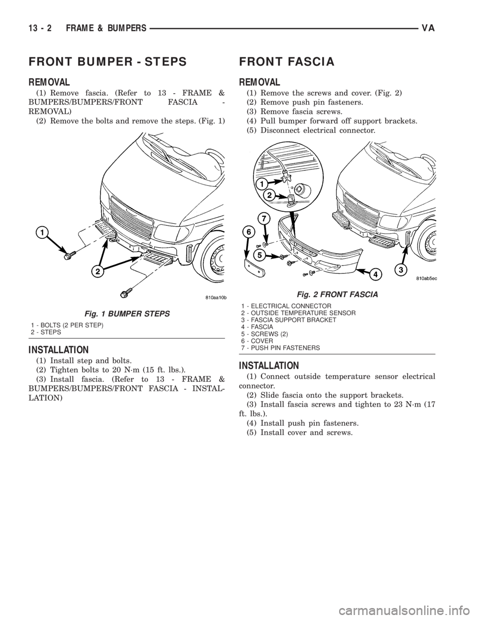
(2) Remove the bolts and remove the steps. (Fig. 1)
INSTALLATION
(1) Install step and bolts.
(2) Tighten bolts to 20 N´m (15 ft. lbs.).
(3) Install fascia. (Refer to 13 - FRAME &
BUMPERS/BUMPERS/FRONT FASCIA - INSTAL-
LATION)
FRONT FASCIA
REMOVAL
(1) Remove the screws and cover. (Fig. 2)
(2) Remove push pin fasteners.
(3) Remove fascia screws.
(4) Pull bumper forward off support brackets.
(5) Disconnect electrical connector.
INSTALLATION
(1) Connect outside temperature sensor electrical
connector.
(2) Slide fascia onto the support brackets.
(3) Install fascia screws and tighten to 23 N´m (17
ft. lbs.).
(4) Install push pin fasteners.
(5) Install cover and screws.
Fig. 1 BUMPER STEPS
1 - BOLTS (2 PER STEP)
2 - STEPS
Fig. 2 FRONT FASCIA
1 - ELECTRICAL CONNECTOR
2 - OUTSIDE TEMPERATURE SENSOR
3 - FASCIA SUPPORT BRACKET
4 - FASCIA
5 - SCREWS (2)
6 - COVER
7 - PUSH PIN FASTENERS
13 - 2 FRAME & BUMPERSVA