MERCEDES-BENZ SPRINTER 2005 Service Repair Manual
Manufacturer: MERCEDES-BENZ, Model Year: 2005, Model line: SPRINTER, Model: MERCEDES-BENZ SPRINTER 2005Pages: 1232, PDF Size: 39.23 MB
Page 841 of 1232
INSTALLATION
(1) If fuel tank is to be replaced, install fuel tank
module into tank. Refer to Fuel Tank Module Remov-
al/Installation procedures.
(2) Position fuel tank to hydraulic jack.
(3) Raise tank until positioned near body.
(4) Connect fuel tank module electrical connector
at top of tank.
(5) Connect fuel supply and return lines.
(6) Continue raising tank while guiding fill hose
into body. Raise tank until positioned snug to body.
(7) Install and position both fuel tank support
straps to mounting studs.
(8) Install 2 fuel tank strap nuts. Refer to Torque
Specifications.
(9) Remove hydraulic jack.
(10) Connect fill and vent hoses to body. Install
ground wire to fill hose.
(11) Lower vehicle.
(12) Fill fuel tank with fuel.
(13) Start engine and check for fuel leaks near top
of module.
FUEL TANK MODULE
DESCRIPTION
An electric fuel pump isnot usedin the fuel tank
module for diesel powered engines. Fuel is supplied
to the fuel injection pump by the fuel transfer (lift)
pump.
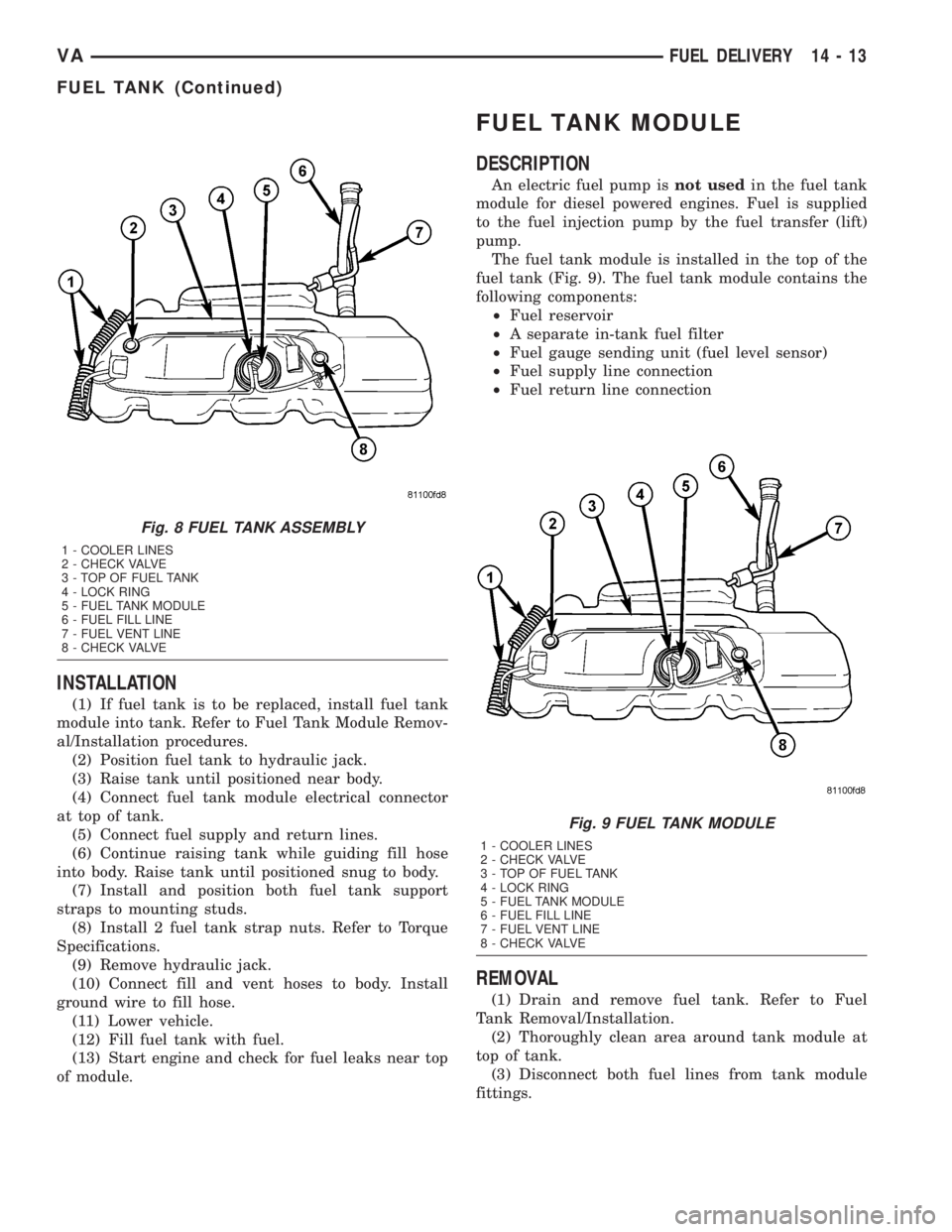
The fuel tank module is installed in the top of the
fuel tank (Fig. 9). The fuel tank module contains the
following components:
²Fuel reservoir
²A separate in-tank fuel filter
²Fuel gauge sending unit (fuel level sensor)
²Fuel supply line connection
²Fuel return line connection
REMOVAL
(1) Drain and remove fuel tank. Refer to Fuel
Tank Removal/Installation.
(2) Thoroughly clean area around tank module at
top of tank.
(3) Disconnect both fuel lines from tank module
fittings.
Fig. 8 FUEL TANK ASSEMBLY
1 - COOLER LINES
2 - CHECK VALVE
3 - TOP OF FUEL TANK
4 - LOCK RING
5 - FUEL TANK MODULE
6 - FUEL FILL LINE
7 - FUEL VENT LINE
8 - CHECK VALVE
Fig. 9 FUEL TANK MODULE
1 - COOLER LINES
2 - CHECK VALVE
3 - TOP OF FUEL TANK
4 - LOCK RING
5 - FUEL TANK MODULE
6 - FUEL FILL LINE
7 - FUEL VENT LINE
8 - CHECK VALVE
VAFUEL DELIVERY 14 - 13
FUEL TANK (Continued)
Page 842 of 1232
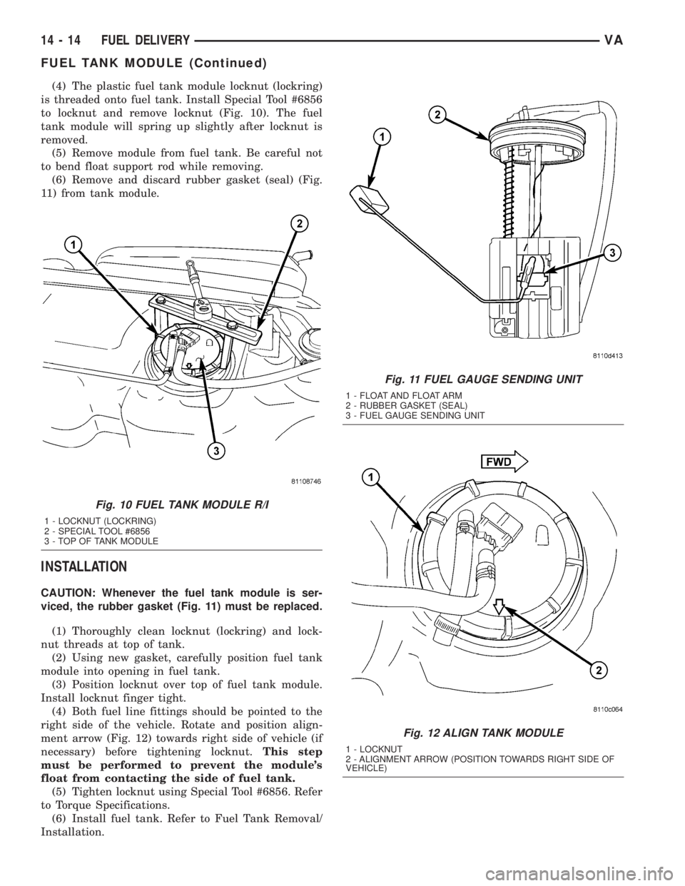
(4) The plastic fuel tank module locknut (lockring)
is threaded onto fuel tank. Install Special Tool #6856
to locknut and remove locknut (Fig. 10). The fuel
tank module will spring up slightly after locknut is
removed.
(5) Remove module from fuel tank. Be careful not
to bend float support rod while removing.
(6) Remove and discard rubber gasket (seal) (Fig.
11) from tank module.
INSTALLATION
CAUTION: Whenever the fuel tank module is ser-
viced, the rubber gasket (Fig. 11) must be replaced.
(1) Thoroughly clean locknut (lockring) and lock-
nut threads at top of tank.
(2) Using new gasket, carefully position fuel tank
module into opening in fuel tank.
(3) Position locknut over top of fuel tank module.
Install locknut finger tight.
(4) Both fuel line fittings should be pointed to the
right side of the vehicle. Rotate and position align-
ment arrow (Fig. 12) towards right side of vehicle (if
necessary) before tightening locknut.This step
must be performed to prevent the module's
float from contacting the side of fuel tank.
(5) Tighten locknut using Special Tool #6856. Refer
to Torque Specifications.
(6) Install fuel tank. Refer to Fuel Tank Removal/
Installation.
Fig. 10 FUEL TANK MODULE R/I
1 - LOCKNUT (LOCKRING)
2 - SPECIAL TOOL #6856
3 - TOP OF TANK MODULE
Fig. 11 FUEL GAUGE SENDING UNIT
1 - FLOAT AND FLOAT ARM
2 - RUBBER GASKET (SEAL)
3 - FUEL GAUGE SENDING UNIT
Fig. 12 ALIGN TANK MODULE
1 - LOCKNUT
2 - ALIGNMENT ARROW (POSITION TOWARDS RIGHT SIDE OF
VEHICLE)
14 - 14 FUEL DELIVERYVA
FUEL TANK MODULE (Continued)
Page 843 of 1232
FUEL LEVEL SENDING UNIT /
SENSOR
DESCRIPTION
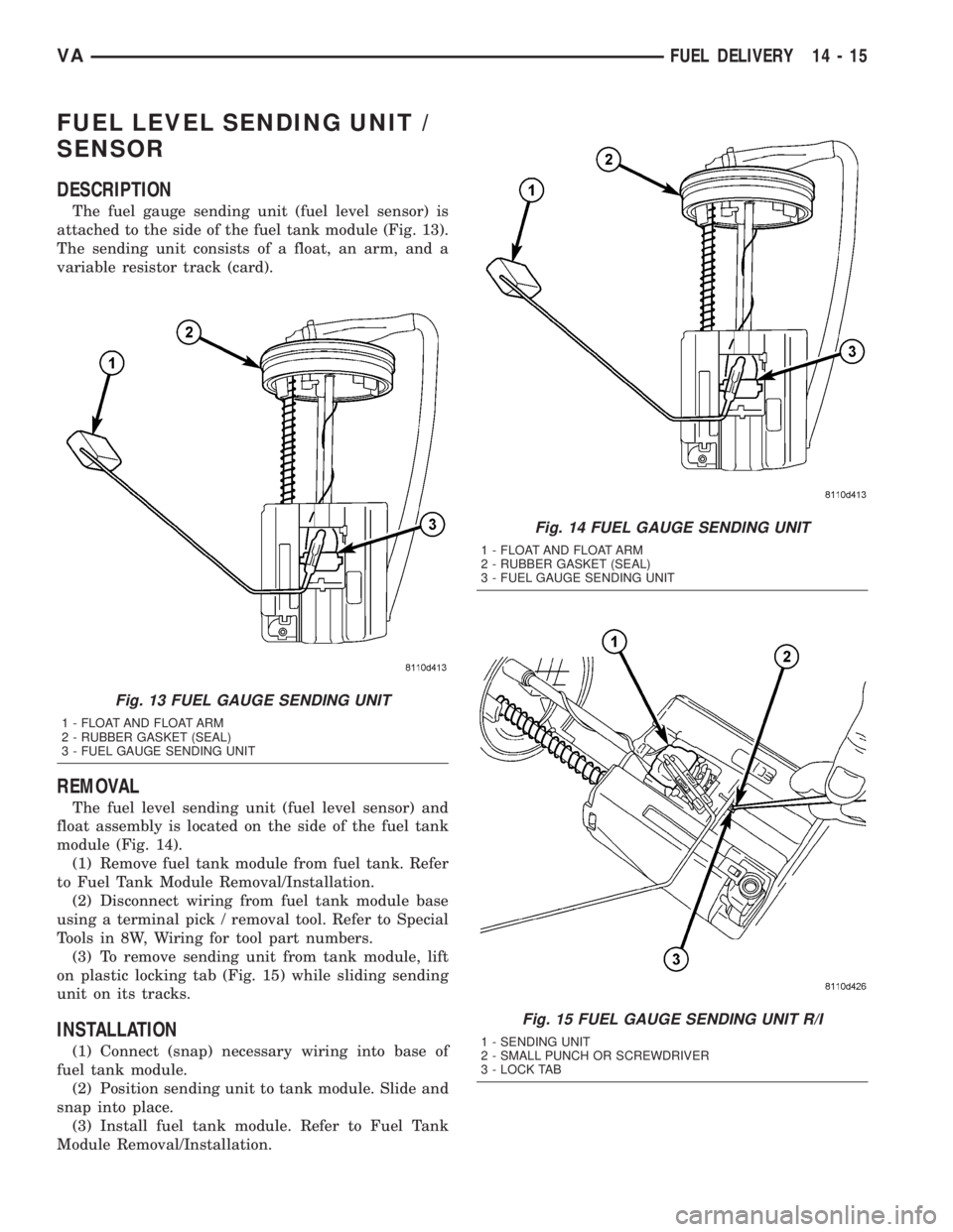
The fuel gauge sending unit (fuel level sensor) is
attached to the side of the fuel tank module (Fig. 13).
The sending unit consists of a float, an arm, and a
variable resistor track (card).
REMOVAL
The fuel level sending unit (fuel level sensor) and
float assembly is located on the side of the fuel tank
module (Fig. 14).
(1) Remove fuel tank module from fuel tank. Refer
to Fuel Tank Module Removal/Installation.
(2) Disconnect wiring from fuel tank module base
using a terminal pick / removal tool. Refer to Special
Tools in 8W, Wiring for tool part numbers.
(3) To remove sending unit from tank module, lift
on plastic locking tab (Fig. 15) while sliding sending
unit on its tracks.
INSTALLATION
(1) Connect (snap) necessary wiring into base of
fuel tank module.
(2) Position sending unit to tank module. Slide and
snap into place.
(3) Install fuel tank module. Refer to Fuel Tank
Module Removal/Installation.
Fig. 13 FUEL GAUGE SENDING UNIT
1 - FLOAT AND FLOAT ARM
2 - RUBBER GASKET (SEAL)
3 - FUEL GAUGE SENDING UNIT
Fig. 14 FUEL GAUGE SENDING UNIT
1 - FLOAT AND FLOAT ARM
2 - RUBBER GASKET (SEAL)
3 - FUEL GAUGE SENDING UNIT
Fig. 15 FUEL GAUGE SENDING UNIT R/I
1 - SENDING UNIT
2 - SMALL PUNCH OR SCREWDRIVER
3 - LOCK TAB
VAFUEL DELIVERY 14 - 15
Page 844 of 1232
HI PRESSURE FUEL SHUTOFF
SOL
DESCRIPTION
The high pressure fuel injection pump has a inte-
grated shut off valve for one of the high pressure
pump elements. The ECM monitors the fuel temper-
ature and will switch off the element if the fuel tem-
perature reaches above 287ÉF (120C) with the engine
speed above 2200 rpm. The shut off valve is not ser-
viced separately.
OPERATION
The high pressure injection pump element shut off
valve interrupts the fuel high pressure delivery of
one of the injection pump elements in the part load
range. This will reduce the power required for driv-
ing the high pressure pump so as to reduce the fuel
temperature. The pump element is switched off if the
fuel temperature is excessively high forcing it to
return again to the fuel feed to cool. The element
shut off limits the increasing pressure of the injection
pump to ensure that the critical fuel temperature for
the system is not exceeded.
WATER IN FUEL SENSOR
DESCRIPTION
The water in fuel sensor if located in the bottom of
the fuel filter housing. This sensor detects the pres-
ence of water in the fuel. If water is present in the
fuel a signal is sent to the ECM and the ECM signals
the instrument cluster, over the CAN bus, to illumi-
nate the water in fuel warning.
OPERATION
The non-dielectric properties of the water allow the
sensors probes to close the electronic circuit when
water is present in the system. When diesel fuel is
present in the system, it's dielectric (does not conduct
electricity well) properties do not allow any electrical
contact between the probes. A 12V power signal is
always present in order to illuminate the indicator on
the instrument cluster. For removal and installation
procedure refer to (Refer to 14 - FUEL SYSTEM/
FUEL DELIVERY/FUEL FILTER - REMOVAL).
14 - 16 FUEL DELIVERYVA
Page 845 of 1232
FUEL INJECTION
TABLE OF CONTENTS
page page
ACCELERATOR PEDAL POSITION SENSOR
DESCRIPTION.........................17
BOOST PRESSURE SENSOR
DESCRIPTION.........................17
OPERATION...........................18
DIAGNOSIS AND TESTING - BOOST
PRESSURE SENSOR..................18
REMOVAL.............................18
INSTALLATION.........................18
CAMSHAFT POSITION SENSOR
DESCRIPTION.........................19
OPERATION...........................19
REMOVAL.............................19
INSTALLATION.........................19
CRANKSHAFT POSITION SENSOR
DESCRIPTION.........................20
OPERATION...........................20
REMOVAL.............................20
INSTALLATION.........................20
FUEL INJECTOR
DESCRIPTION
FUEL INJECTOR......................20
OPERATION...........................20
STANDARD PROCEDURE
STANDARD PROCEDURE - INJECTOR
CLASSIFICATION.....................22
STANDARD PROCEDURE - CLEANING
FUEL INJECTORS.....................22
REMOVAL.............................23
INSTALLATION.........................23
FUEL PRESSURE SENSOR
DESCRIPTION
DESCRIPTION........................25DESCRIPTION........................25
OPERATION
OPERATION.........................25
OPERATION.........................25
REMOVAL
REMOVAL...........................26
REMOVAL...........................26
INSTALLATION
INSTALLATION.......................26
INSTALLATION.......................27
FUEL PRESSURE SOLENOID
DESCRIPTION.........................27
OPERATION...........................27
REMOVAL.............................28
INSTALLATION.........................28
FUEL TEMPERATURE SENSOR
DESCRIPTION.........................29
OPERATION...........................29
REMOVAL.............................29
INSTALLATION.........................29
INLET AIR TEMPERATURE SENSOR
DESCRIPTION.........................29
OPERATION...........................29
REMOVAL.............................30
INSTALLATION.........................30
MANIFOLD AIR FLOW (MAF) SENSOR
DESCRIPTION.........................30
OPERATION...........................30
REMOVAL.............................31
INSTALLATION.........................31
ACCELERATOR PEDAL
POSITION SENSOR
DESCRIPTION
The accelerator pedal position sensor is located on
the accelerator pedal assembly. The driver supplies
the torque requirements for the engine by operating
the accelerator pedal in accordance with the desired
speed or acceleration. The pedal sensor converts the
mechanical operation of the pedal into an electrical
signal and sends the information to the ECM. The
ECM adjusts the quantity of the fuel that is injected
into the engine (Fig. 1).The accelerator pedal position sensor is serviced as
an assembly with the accelerator assembly.
BOOST PRESSURE SENSOR
DESCRIPTION
The boost pressure sensor is mounted to the charge
air pipe (Fig. 2). The sensor allows the ECM to mon-
itor intake air down stream of the turbocharger.
VAFUEL INJECTION 14 - 17
Page 846 of 1232
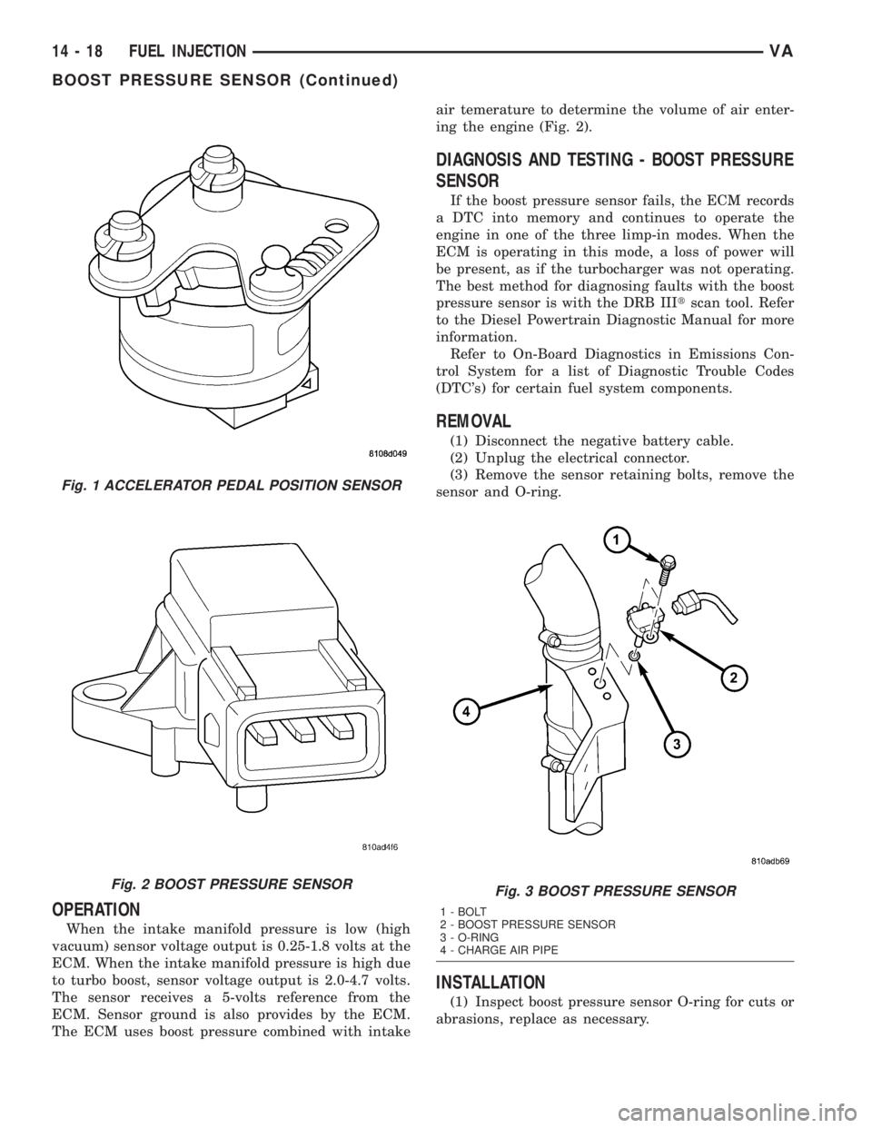
OPERATION
When the intake manifold pressure is low (high
vacuum) sensor voltage output is 0.25-1.8 volts at the
ECM. When the intake manifold pressure is high due
to turbo boost, sensor voltage output is 2.0-4.7 volts.
The sensor receives a 5-volts reference from the
ECM. Sensor ground is also provides by the ECM.
The ECM uses boost pressure combined with intakeair temerature to determine the volume of air enter-
ing the engine (Fig. 2).
DIAGNOSIS AND TESTING - BOOST PRESSURE
SENSOR
If the boost pressure sensor fails, the ECM records
a DTC into memory and continues to operate the
engine in one of the three limp-in modes. When the
ECM is operating in this mode, a loss of power will
be present, as if the turbocharger was not operating.
The best method for diagnosing faults with the boost
pressure sensor is with the DRB IIItscan tool. Refer
to the Diesel Powertrain Diagnostic Manual for more
information.
Refer to On-Board Diagnostics in Emissions Con-
trol System for a list of Diagnostic Trouble Codes
(DTC's) for certain fuel system components.
REMOVAL
(1) Disconnect the negative battery cable.
(2) Unplug the electrical connector.
(3) Remove the sensor retaining bolts, remove the
sensor and O-ring.
INSTALLATION
(1) Inspect boost pressure sensor O-ring for cuts or
abrasions, replace as necessary.
Fig. 1 ACCELERATOR PEDAL POSITION SENSOR
Fig. 2 BOOST PRESSURE SENSORFig. 3 BOOST PRESSURE SENSOR
1 - BOLT
2 - BOOST PRESSURE SENSOR
3 - O-RING
4 - CHARGE AIR PIPE
14 - 18 FUEL INJECTIONVA
BOOST PRESSURE SENSOR (Continued)
Page 847 of 1232
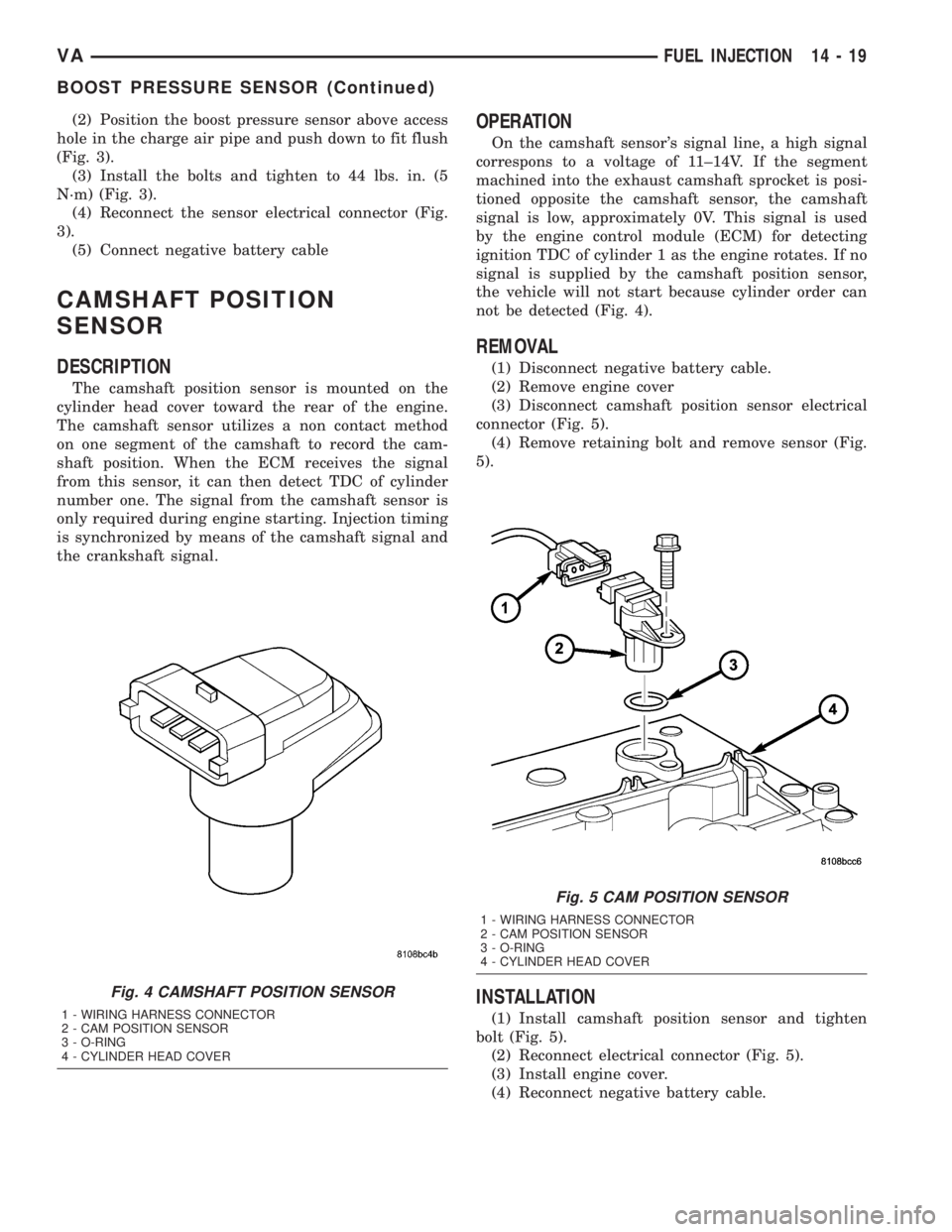
(2) Position the boost pressure sensor above access
hole in the charge air pipe and push down to fit flush
(Fig. 3).
(3) Install the bolts and tighten to 44 lbs. in. (5
N´m) (Fig. 3).
(4) Reconnect the sensor electrical connector (Fig.
3).
(5) Connect negative battery cable
CAMSHAFT POSITION
SENSOR
DESCRIPTION
The camshaft position sensor is mounted on the
cylinder head cover toward the rear of the engine.
The camshaft sensor utilizes a non contact method
on one segment of the camshaft to record the cam-
shaft position. When the ECM receives the signal
from this sensor, it can then detect TDC of cylinder
number one. The signal from the camshaft sensor is
only required during engine starting. Injection timing
is synchronized by means of the camshaft signal and
the crankshaft signal.
OPERATION
On the camshaft sensor's signal line, a high signal
correspons to a voltage of 11±14V. If the segment
machined into the exhaust camshaft sprocket is posi-
tioned opposite the camshaft sensor, the camshaft
signal is low, approximately 0V. This signal is used
by the engine control module (ECM) for detecting
ignition TDC of cylinder 1 as the engine rotates. If no
signal is supplied by the camshaft position sensor,
the vehicle will not start because cylinder order can
not be detected (Fig. 4).
REMOVAL
(1) Disconnect negative battery cable.
(2) Remove engine cover
(3) Disconnect camshaft position sensor electrical
connector (Fig. 5).
(4) Remove retaining bolt and remove sensor (Fig.
5).
INSTALLATION
(1) Install camshaft position sensor and tighten
bolt (Fig. 5).
(2) Reconnect electrical connector (Fig. 5).
(3) Install engine cover.
(4) Reconnect negative battery cable.
Fig. 4 CAMSHAFT POSITION SENSOR
1 - WIRING HARNESS CONNECTOR
2 - CAM POSITION SENSOR
3 - O-RING
4 - CYLINDER HEAD COVER
Fig. 5 CAM POSITION SENSOR
1 - WIRING HARNESS CONNECTOR
2 - CAM POSITION SENSOR
3 - O-RING
4 - CYLINDER HEAD COVER
VAFUEL INJECTION 14 - 19
BOOST PRESSURE SENSOR (Continued)
Page 848 of 1232
CRANKSHAFT POSITION
SENSOR
DESCRIPTION
The crankshaft position sensor is located opposite
the teeth on the flywheel and uses a non contact
method to record the position of the crankshaft. The
leading edges of each tooth on the flywheel generate
a positive signal in the position sensor, while the
trailing edges generate a negative signal. When the
crankshaft is rotating, an alternating voltage is pro-
duced as a result.
The period of the signal is the time required by the
crankshaft to turn through the gap between two fly-
wheel teeth. The clearance between the crankshaft
position sensor and the teeth of the flywheel is fixed
by the installation.
Two teeth on the flywheel are missing. The result-
ing signal gap is used by the ECM to detect the TDC
position of cylinder number one.
OPERATION
The clearance between the crankshaft position sen-
sor and the flywheel are fixed by the installation
position. Two teeth on the flywheel are missing. The
resulting gap is used by the ECM to detect DTC of
cylinder number one. The crankshaft position is cal-
culated to an accuracy of a fraction of a degree so
that the start and end of injection can occur at
exactly the right moment. The engine speed signal is
also processed by the ECM from the crankshaft sen-
sor. This signal is then transferred to other control
modules over the CAN bus.
If the crankshaft position sensor fails, the signal
that provides reference rotation is missing. Injection
may occur at the wrong time and damage the engine.
In this case, the ECM will stop triggering the injec-
tors, the engine would cut out, the engine warning
light would illuminate and the engine will not
restart.
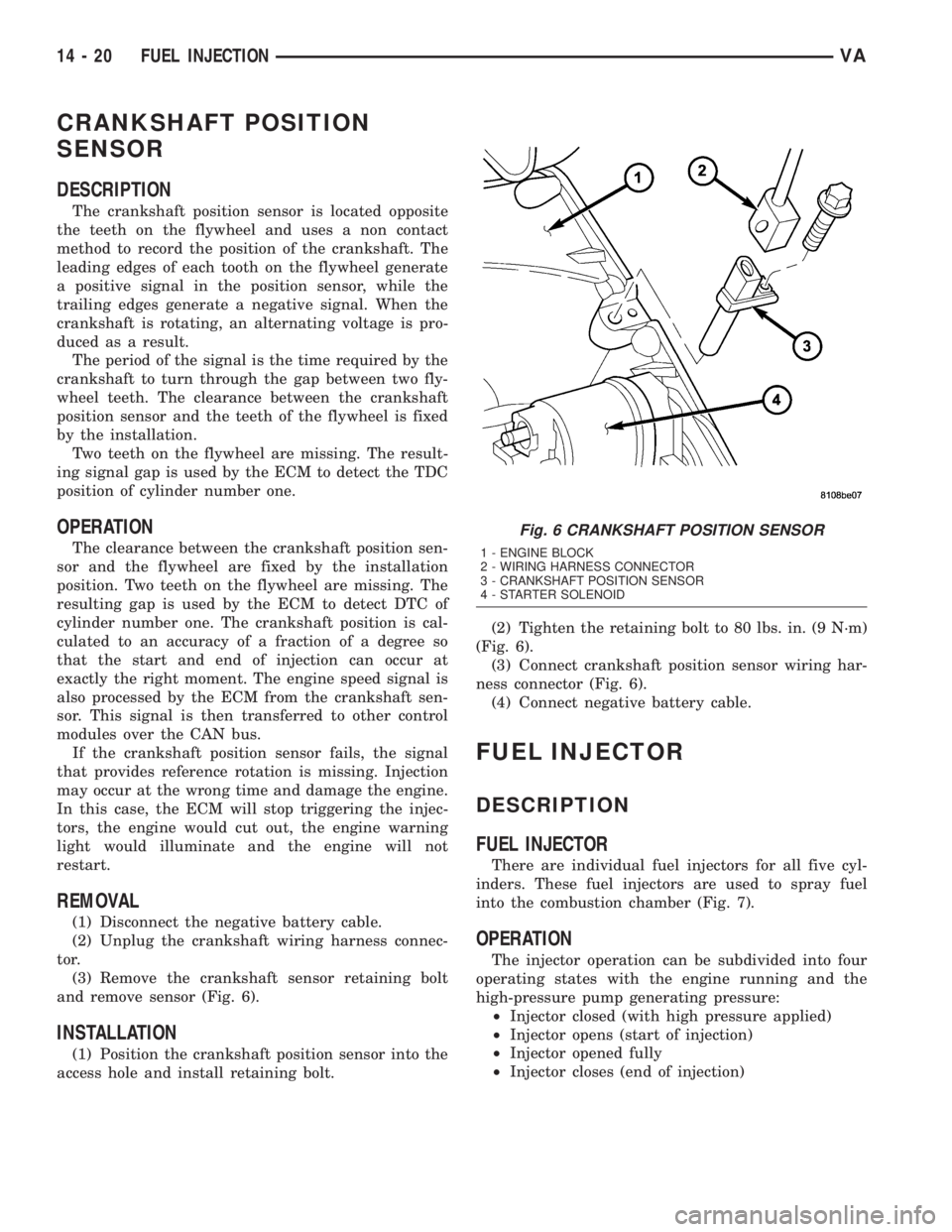
REMOVAL
(1) Disconnect the negative battery cable.
(2) Unplug the crankshaft wiring harness connec-
tor.
(3) Remove the crankshaft sensor retaining bolt
and remove sensor (Fig. 6).
INSTALLATION
(1) Position the crankshaft position sensor into the
access hole and install retaining bolt.(2) Tighten the retaining bolt to 80 lbs. in. (9 N´m)
(Fig. 6).
(3) Connect crankshaft position sensor wiring har-
ness connector (Fig. 6).
(4) Connect negative battery cable.
FUEL INJECTOR
DESCRIPTION
FUEL INJECTOR
There are individual fuel injectors for all five cyl-
inders. These fuel injectors are used to spray fuel
into the combustion chamber (Fig. 7).
OPERATION
The injector operation can be subdivided into four
operating states with the engine running and the
high-pressure pump generating pressure:
²Injector closed (with high pressure applied)
²Injector opens (start of injection)
²Injector opened fully
²Injector closes (end of injection)
Fig. 6 CRANKSHAFT POSITION SENSOR
1 - ENGINE BLOCK
2 - WIRING HARNESS CONNECTOR
3 - CRANKSHAFT POSITION SENSOR
4 - STARTER SOLENOID
14 - 20 FUEL INJECTIONVA
Page 849 of 1232
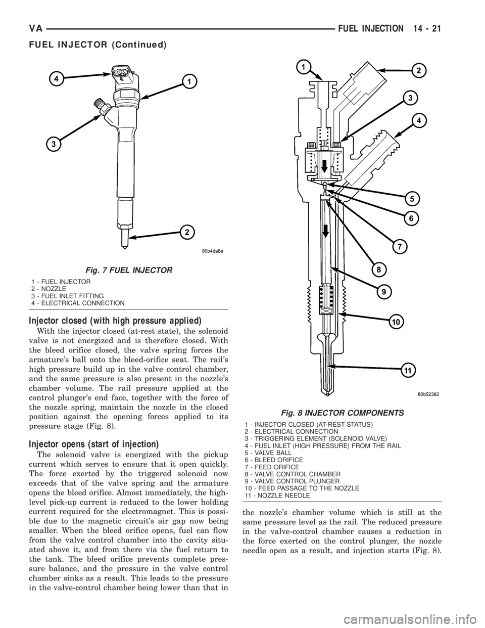
Injector closed (with high pressure applied)
With the injector closed (at-rest state), the solenoid
valve is not energized and is therefore closed. With
the bleed orifice closed, the valve spring forces the
armature's ball onto the bleed-orifice seat. The rail's
high pressure build up in the valve control chamber,
and the same pressure is also present in the nozzle's
chamber volume. The rail pressure applied at the
control plunger's end face, together with the force of
the nozzle spring, maintain the nozzle in the closed
position against the opening forces applied to its
pressure stage (Fig. 8).
Injector opens (start of injection)
The solenoid valve is energized with the pickup
current which serves to ensure that it open quickly.
The force exerted by the triggered solenoid now
exceeds that of the valve spring and the armature
opens the bleed orifice. Almost immediately, the high-
level pick-up current is reduced to the lower holding
current required for the electromagnet. This is possi-
ble due to the magnetic circuit's air gap now being
smaller. When the bleed orifice opens, fuel can flow
from the valve control chamber into the cavity situ-
ated above it, and from there via the fuel return to
the tank. The bleed orifice prevents complete pres-
sure balance, and the pressure in the valve control
chamber sinks as a result. This leads to the pressure
in the valve-control chamber being lower than that inthe nozzle's chamber volume which is still at the
same pressure level as the rail. The reduced pressure
in the valve-control chamber causes a reduction in
the force exerted on the control plunger, the nozzle
needle open as a result, and injection starts (Fig. 8).
Fig. 7 FUEL INJECTOR
1 - FUEL INJECTOR
2 - NOZZLE
3 - FUEL INLET FITTING
4 - ELECTRICAL CONNECTION
Fig. 8 INJECTOR COMPONENTS
1 - INJECTOR CLOSED (AT-REST STATUS)
2 - ELECTRICAL CONNECTION
3 - TRIGGERING ELEMENT (SOLENOID VALVE)
4 - FUEL INLET (HIGH PRESSURE) FROM THE RAIL
5 - VALVE BALL
6 - BLEED ORIFICE
7 - FEED ORIFICE
8 - VALVE CONTROL CHAMBER
9 - VALVE CONTROL PLUNGER
10 - FEED PASSAGE TO THE NOZZLE
11 - NOZZLE NEEDLE
VAFUEL INJECTION 14 - 21
FUEL INJECTOR (Continued)
Page 850 of 1232
Injector opens fully
The control plunger reaches its upper stop where it
remains supported by a cushion of fuel which is gen-
erated by the flow of fuel between the bleed and feed
orifices. The injector nozzle has now opened fully,
and the fuel is injected into the combustion chamber
at a pressure almost equal to that in the fuel rail
(Fig. 8).
Injector closes (end of injection)
As soon as the solenoid valve is no longer trig-
gered, the valve spring forces the armature down-
wards and the ball closes the bleed orifice. The
armature is a 2±piece design. Here, although the
armature plate is guided by a driver shoulder in its
downward movement, it can ªoverspringº with the
return spring so that it exerts no downwards-acting
forces on the armature and the ball. The closing of
the bleed orifice lead to pressure build up in the con-
trol chamber via the input from the feed orifice. This
pressure is the same as that in the rail and exerts an
increased force on the control plunger through its
end face. This force, together with that of the spring,
now exceeds the force exerted by the chamber volume
and the nozzle needle closes. Injection ceases as soon
as the nozzle needle comes up against its bottom stop
again (Fig. 8).
STANDARD PROCEDURE
STANDARD PROCEDURE - INJECTOR
CLASSIFICATION
The classification of injectors into 3 classes
describes the quantity characteristic of the injector.
This will make it possible in the future to match the
engine software to the tolerances of the injector
within a more narrowly graduated range. Classifica-
tion can be clearly recognized, and assigned only by
means of a DRBIIIt.
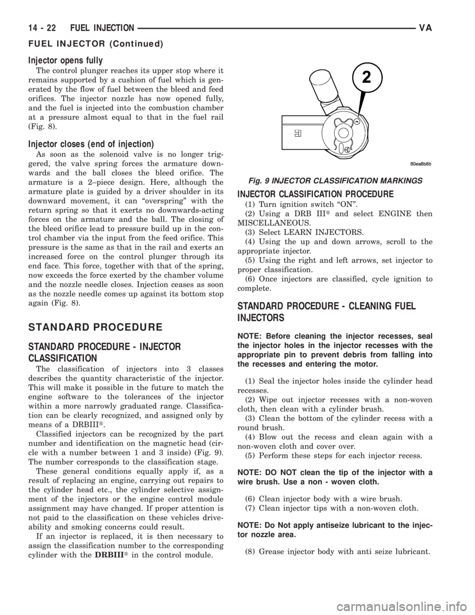
Classified injectors can be recognized by the part
number and identification on the magnetic head (cir-
cle with a number between 1 and 3 inside) (Fig. 9).
The number corresponds to the classification stage.
These general conditions equally apply if, as a
result of replacing an engine, carrying out repairs to
the cylinder head etc., the cylinder selective assign-
ment of the injectors or the engine control module
assignment may have changed. If proper attention is
not paid to the classification on these vehicles drive-
ability and smoking concerns could result.
If an injector is replaced, it is then necessary to
assign the classification number to the corresponding
cylinder with theDRBIIItin the control module.
INJECTOR CLASSIFICATION PROCEDURE
(1) Turn ignition switch ªONº.
(2) Using a DRB IIItand select ENGINE then
MISCELLANEOUS.
(3) Select LEARN INJECTORS.
(4) Using the up and down arrows, scroll to the
appropriate injector.
(5) Using the right and left arrows, set injector to
proper classification.
(6) Once injectors are classified, cycle ignition to
complete.
STANDARD PROCEDURE - CLEANING FUEL
INJECTORS
NOTE: Before cleaning the injector recesses, seal
the injector holes in the injector recesses with the
appropriate pin to prevent debris from falling into
the recesses and entering the motor.
(1) Seal the injector holes inside the cylinder head
recesses.
(2) Wipe out injector recesses with a non-woven
cloth, then clean with a cylinder brush.
(3) Clean the bottom of the cylinder recess with a
round brush.
(4) Blow out the recess and clean again with a
non-woven cloth and cover over.
(5) Perform these steps for each injector recess.
NOTE: DO NOT clean the tip of the injector with a
wire brush. Use a non - woven cloth.
(6) Clean injector body with a wire brush.
(7) Clean injector tips with a non-woven cloth.
NOTE: Do Not apply antiseize lubricant to the injec-
tor nozzle area.
(8) Grease injector body with anti seize lubricant.
Fig. 9 INJECTOR CLASSIFICATION MARKINGS
14 - 22 FUEL INJECTIONVA
FUEL INJECTOR (Continued)