MERCEDES-BENZ SPRINTER 2006 Service Manual
SPRINTER 2006
MERCEDES-BENZ
MERCEDES-BENZ
https://www.carmanualsonline.info/img/4/57081/w960_57081-0.png
MERCEDES-BENZ SPRINTER 2006 Service Manual
Trending: wiring, remote start, height, tyre pressure, wheelbase, spare wheel, tailgate
Page 401 of 2305
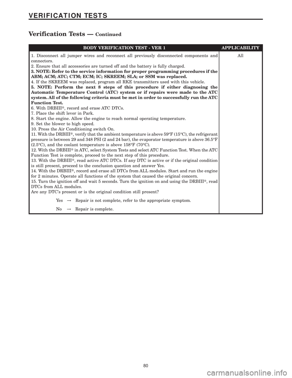
BODY VERIFICATION TEST - VER 1 APPLICABILITY
1. Disconnect all jumper wires and reconnect all previously disconnected components and
connectors.
2. Ensure that all accessories are turned off and the battery is fully charged.
3. NOTE: Refer to the service information for proper programming procedures if the
ABM; ACM; ATC; CTM; ECM; IC; SKREEM; SLA; or SSM was replaced.
4. If the SKREEM was replaced, program all RKE transmitters used with this vehicle.
5. NOTE: Perform the next 8 steps of this procedure if either diagnosing the
Automatic Temperature Control (ATC) system or if repairs were made to the ATC
system. All of the following criteria must be met in order to successfully run the ATC
Function Test.
6. With DRBIIIt, record and erase ATC DTCs.
7. Place the shift lever in Park.
8. Start the engine. Allow the engine to reach normal operating temperature.
9. Set the blower to high speed.
10. Press the Air Conditioning switch On.
11. With the DRBIIIt, verify that the ambient temperature is above 59ÉF (15ÉC), the refrigerant
pressure is between 29 and 348 PSI (2 and 24 bar), the evaporator temperature is above 36.5ÉF
(2.5ÉC), and the coolant temperature is above 158ÉF (70ÉC).
12. With the DRBIIItin ATC, select System Tests and select ATC Function Test. When the ATC
Function Test is complete, proceed to the next step of this procedure.
13. With the DRBIIIt, read active ATC DTCs. If any DTC is active or if the original condition
is still present, proceed to the conclusion question and answer Yes.
14. With the DRBIIIt, record and erase all DTCs from ALL modules. Start and run the engine
for 2 minutes. Operate all functions of the system that caused the original concern.
15. Turn the ignition off and wait 5 seconds. Turn the ignition on and using the DRBIIIt, read
DTCs from ALL modules.
Are any DTC's present or is the original condition still present?All
Ye s!Repair is not complete, refer to the appropriate symptom.
No!Repair is complete.
80
VERIFICATION TESTS
Verification Tests ÐContinued
Page 402 of 2305
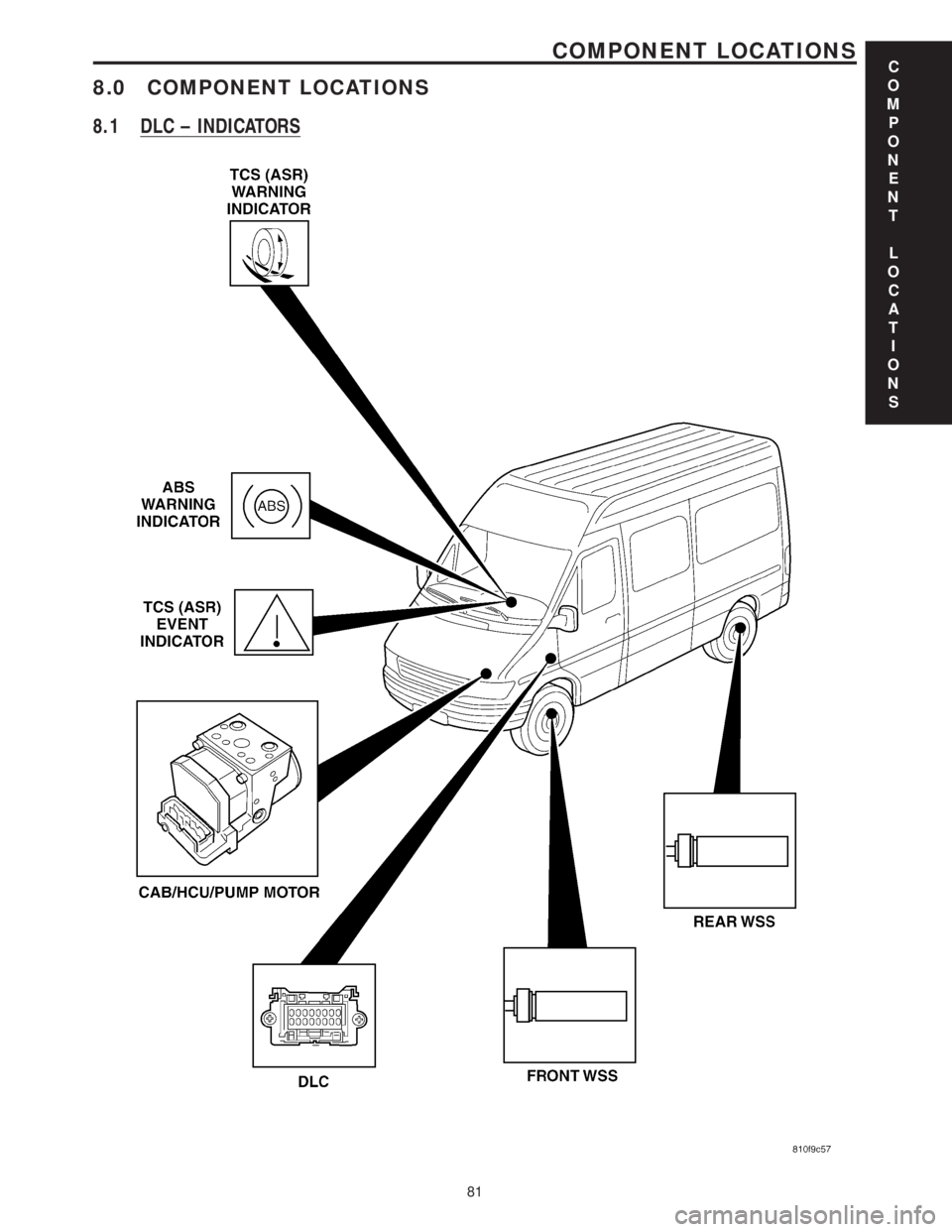
8.0 COMPONENT LOCATIONS
8.1 DLC ± INDICATORS
C
O
M
P
O
N
E
N
T
L
O
C
A
T
I
O
N
S
81
COMPONENT LOCATIONS
Page 403 of 2305
8.2 CAB ± WSS
C
O
M
P
O
N
E
N
T
L
O
C
A
T
I
O
N
S
82
COMPONENT LOCATIONS
Page 404 of 2305
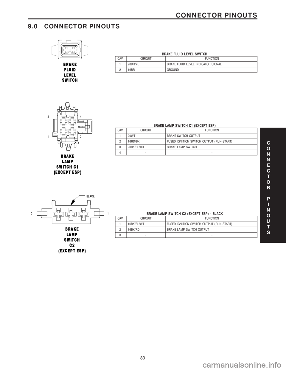
9.0 CONNECTOR PINOUTS
BRAKE FLUID LEVEL SWITCHCAV CIRCUIT FUNCTION
1 20BR/YL BRAKE FLUID LEVEL INDICATOR SIGNAL
2 16BR GROUND
BRAKE LAMP SWITCH C1 (EXCEPT ESP)CAV CIRCUIT FUNCTION
1 20WT BRAKE SWITCH OUTPUT
2 16RD/BK FUSED IGNITION SWITCH OUTPUT (RUN-START)
3 20BK/BL/RD BRAKE LAMP SWITCH
4- -
BRAKE LAMP SWITCH C2 (EXCEPT ESP) - BLACKCAV CIRCUIT FUNCTION
1 16BK/BL/WT FUSED IGNITION SWITCH OUTPUT (RUN-START)
2 16BK/RD BRAKE LAMP SWITCH OUTPUT
3- -
C
O
N
N
E
C
T
O
R
P
I
N
O
U
T
S
83
CONNECTOR PINOUTS
Page 405 of 2305
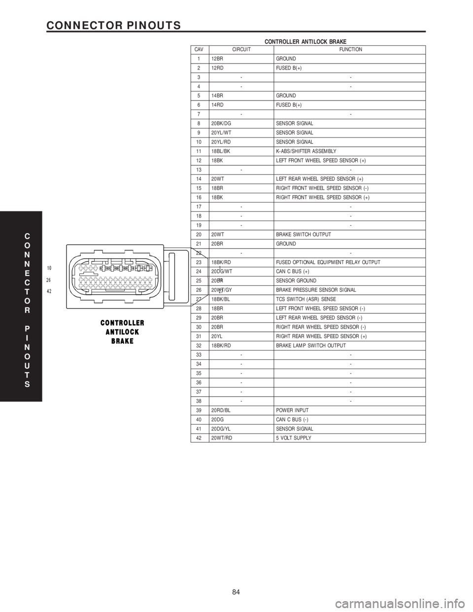
CONTROLLER ANTILOCK BRAKECAV CIRCUIT FUNCTION
1 12BR GROUND
2 12RD FUSED B(+)
3- -
4- -
5 14BR GROUND
6 14RD FUSED B(+)
7- -
8 20BK/DG SENSOR SIGNAL
9 20YL/WT SENSOR SIGNAL
10 20YL/RD SENSOR SIGNAL
11 18BL/BK K-ABS/SHIFTER ASSEMBLY
12 18BK LEFT FRONT WHEEL SPEED SENSOR (+)
13 - -
14 20WT LEFT REAR WHEEL SPEED SENSOR (+)
15 18BR RIGHT FRONT WHEEL SPEED SENSOR (-)
16 18BK RIGHT FRONT WHEEL SPEED SENSOR (+)
17 - -
18 - -
19 - -
20 20WT BRAKE SWITCH OUTPUT
21 20BR GROUND
22 - -
23 18BK/RD FUSED OPTIONAL EQUIPMENT RELAY OUTPUT
24 20DG/WT CAN C BUS (+)
25 20BR SENSOR GROUND
26 20WT/GY BRAKE PRESSURE SENSOR SIGNAL
27 18BK/BL TCS SWITCH (ASR) SENSE
28 18BR LEFT FRONT WHEEL SPEED SENSOR (-)
29 20BR LEFT REAR WHEEL SPEED SENSOR (-)
30 20BR RIGHT REAR WHEEL SPEED SENSOR (-)
31 20YL RIGHT REAR WHEEL SPEED SENSOR (+)
32 18BK/RD BRAKE LAMP SWITCH OUTPUT
33 - -
34 - -
35 - -
36 - -
37 - -
38 - -
39 20RD/BL POWER INPUT
40 20DG CAN C BUS (-)
41 20DG/YL SENSOR SIGNAL
42 20WT/RD 5 VOLT SUPPLY
C
O
N
N
E
C
T
O
R
P
I
N
O
U
T
S
84
CONNECTOR PINOUTS
Page 406 of 2305
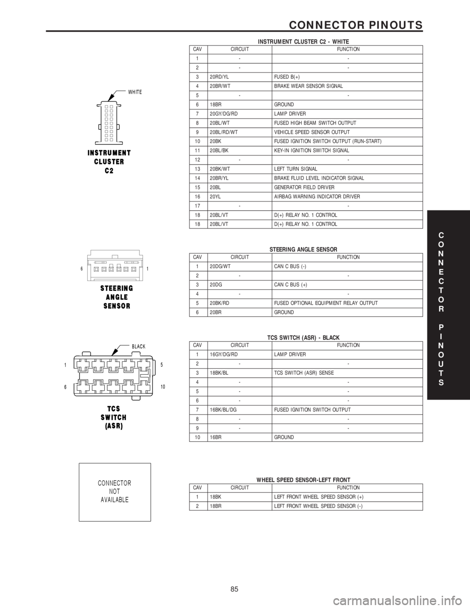
INSTRUMENT CLUSTER C2 - WHITECAV CIRCUIT FUNCTION
1- -
2- -
3 20RD/YL FUSED B(+)
4 20BR/WT BRAKE WEAR SENSOR SIGNAL
5- -
6 18BR GROUND
7 20GY/DG/RD LAMP DRIVER
8 20BL/WT FUSED HIGH BEAM SWITCH OUTPUT
9 20BL/RD/WT VEHICLE SPEED SENSOR OUTPUT
10 20BK FUSED IGNITION SWITCH OUTPUT (RUN-START)
11 20BL/BK KEY-IN IGNITION SWITCH SIGNAL
12 - -
13 20BK/WT LEFT TURN SIGNAL
14 20BR/YL BRAKE FLUID LEVEL INDICATOR SIGNAL
15 20BL GENERATOR FIELD DRIVER
16 20YL AIRBAG WARNING INDICATOR DRIVER
17 - -
18 20BL/VT D(+) RELAY NO. 1 CONTROL
18 20BL/VT D(+) RELAY NO. 1 CONTROL
STEERING ANGLE SENSORCAV CIRCUIT FUNCTION
1 20DG/WT CAN C BUS (-)
2- -
3 20DG CAN C BUS (+)
4- -
5 20BK/RD FUSED OPTIONAL EQUIPMENT RELAY OUTPUT
6 20BR GROUND
TCS SWITCH (ASR) - BLACKCAV CIRCUIT FUNCTION
1 16GY/DG/RD LAMP DRIVER
2- -
3 18BK/BL TCS SWITCH (ASR) SENSE
4- -
5- -
6- -
7 16BK/BL/DG FUSED IGNITION SWITCH OUTPUT
8- -
9- -
10 16BR GROUND
WHEEL SPEED SENSOR-LEFT FRONTCAV CIRCUIT FUNCTION
1 18BK LEFT FRONT WHEEL SPEED SENSOR (+)
2 18BR LEFT FRONT WHEEL SPEED SENSOR (-)
C
O
N
N
E
C
T
O
R
P
I
N
O
U
T
S
85
CONNECTOR PINOUTS
Page 407 of 2305
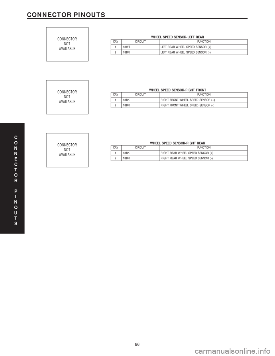
WHEEL SPEED SENSOR-LEFT REARCAV CIRCUIT FUNCTION
1 18WT LEFT REAR WHEEL SPEED SENSOR (+)
2 18BR LEFT REAR WHEEL SPEED SENSOR (-)
WHEEL SPEED SENSOR-RIGHT FRONTCAV CIRCUIT FUNCTION
1 18BK RIGHT FRONT WHEEL SPEED SENSOR (+)
2 18BR RIGHT FRONT WHEEL SPEED SENSOR (-)
WHEEL SPEED SENSOR-RIGHT REARCAV CIRCUIT FUNCTION
1 18BK RIGHT REAR WHEEL SPEED SENSOR (+)
2 18BR RIGHT REAR WHEEL SPEED SENSOR (-)
C
O
N
N
E
C
T
O
R
P
I
N
O
U
T
S
86
CONNECTOR PINOUTS
Page 408 of 2305
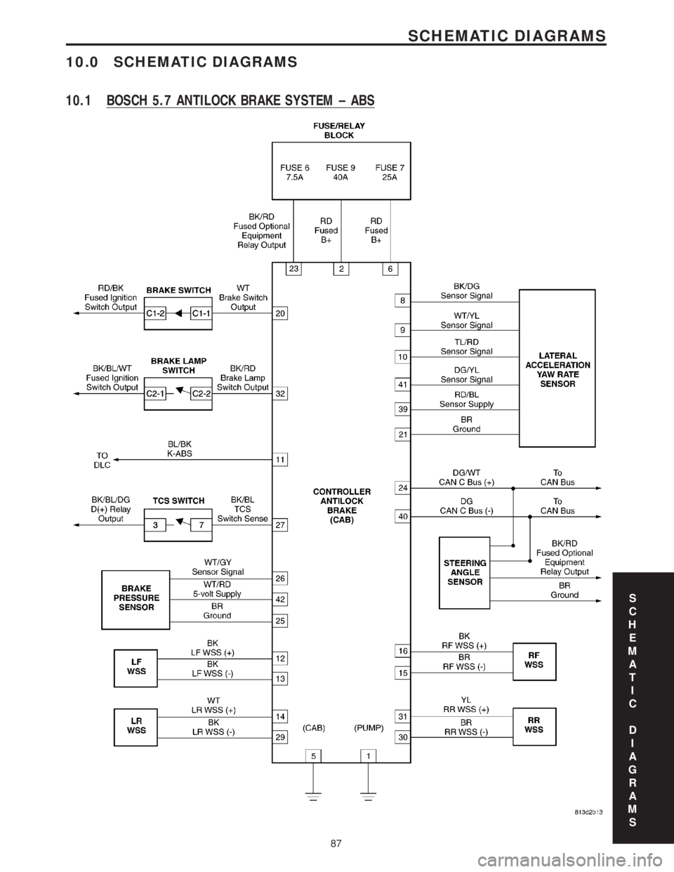
10.0 SCHEMATIC DIAGRAMS
10.1 BOSCH 5.7 ANTILOCK BRAKE SYSTEM ± ABS
S
C
H
E
M
A
T
I
C
D
I
A
G
R
A
M
S
87
SCHEMATIC DIAGRAMS
Page 409 of 2305
Page 410 of 2305
DIAGNOSTIC TEST PROCEDURES — TELL US!
DaimlerChrysler Corporation is constantly working to provide the technician the best diagnostic manuals possible.
Your comments and recommendations regarding the diagnostic manuals and procedures are appreciated.
To best understand your suggestion, please complete the form giving us as much detail as possible.
ModelYearBody TypeEngine
TransmissionVehicle MileageMDH
Diagnostic ProcedureBook No.Page
Comments/recommendations (if necessary, draw sketch)
Name
Submitted by:
Address
City/State/Zip
Business Phone #
All comments become property of DaimlerChrysler Corporation and may be used without compensation.
Trending: lights, center console, load capacity, height, ECU, spare tire, trailer

