MERCEDES-BENZ SPRINTER 2006 Service Manual
Manufacturer: MERCEDES-BENZ, Model Year: 2006, Model line: SPRINTER, Model: MERCEDES-BENZ SPRINTER 2006Pages: 2305, PDF Size: 48.12 MB
Page 371 of 2305
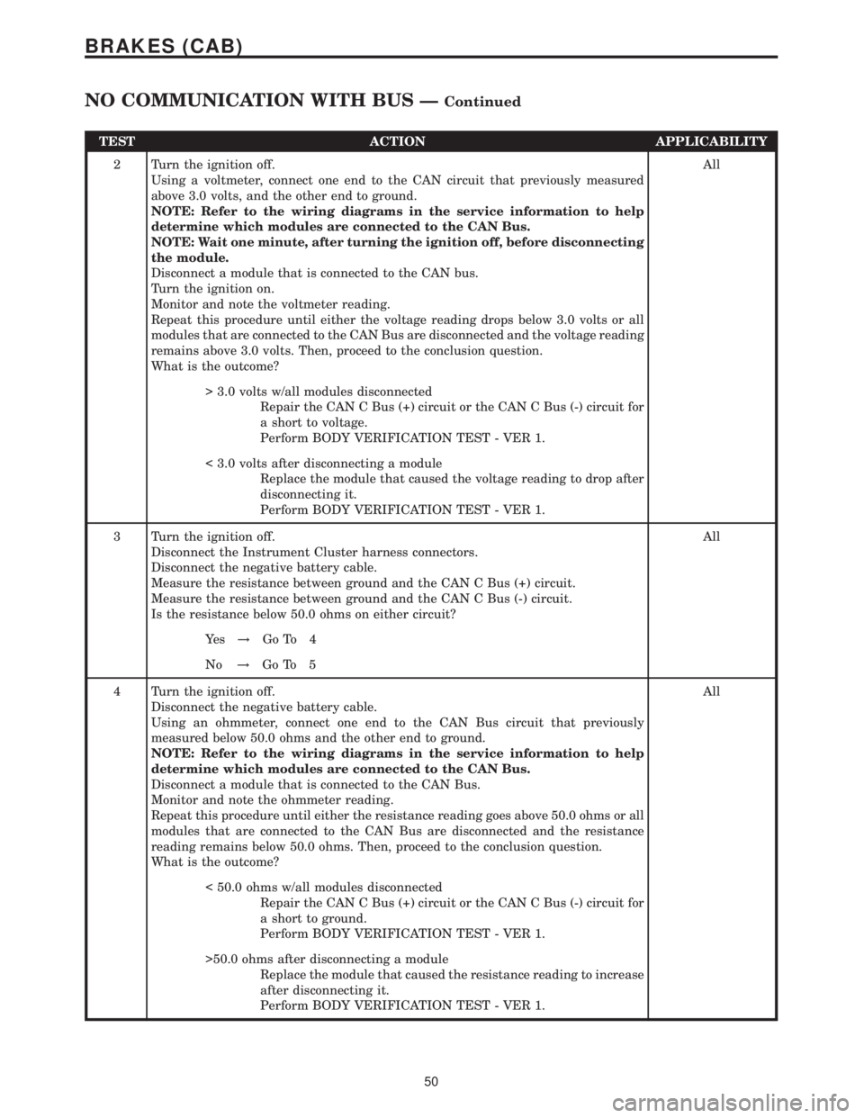
TEST ACTION APPLICABILITY
2 Turn the ignition off.
Using a voltmeter, connect one end to the CAN circuit that previously measured
above 3.0 volts, and the other end to ground.
NOTE: Refer to the wiring diagrams in the service information to help
determine which modules are connected to the CAN Bus.
NOTE: Wait one minute, after turning the ignition off, before disconnecting
the module.
Disconnect a module that is connected to the CAN bus.
Turn the ignition on.
Monitor and note the voltmeter reading.
Repeat this procedure until either the voltage reading drops below 3.0 volts or all
modules that are connected to the CAN Bus are disconnected and the voltage reading
remains above 3.0 volts. Then, proceed to the conclusion question.
What is the outcome?All
> 3.0 volts w/all modules disconnected
Repair the CAN C Bus (+) circuit or the CAN C Bus (-) circuit for
a short to voltage.
Perform BODY VERIFICATION TEST - VER 1.
< 3.0 volts after disconnecting a module
Replace the module that caused the voltage reading to drop after
disconnecting it.
Perform BODY VERIFICATION TEST - VER 1.
3 Turn the ignition off.
Disconnect the Instrument Cluster harness connectors.
Disconnect the negative battery cable.
Measure the resistance between ground and the CAN C Bus (+) circuit.
Measure the resistance between ground and the CAN C Bus (-) circuit.
Is the resistance below 50.0 ohms on either circuit?All
Ye s!Go To 4
No!Go To 5
4 Turn the ignition off.
Disconnect the negative battery cable.
Using an ohmmeter, connect one end to the CAN Bus circuit that previously
measured below 50.0 ohms and the other end to ground.
NOTE: Refer to the wiring diagrams in the service information to help
determine which modules are connected to the CAN Bus.
Disconnect a module that is connected to the CAN Bus.
Monitor and note the ohmmeter reading.
Repeat this procedure until either the resistance reading goes above 50.0 ohms or all
modules that are connected to the CAN Bus are disconnected and the resistance
reading remains below 50.0 ohms. Then, proceed to the conclusion question.
What is the outcome?All
< 50.0 ohms w/all modules disconnected
Repair the CAN C Bus (+) circuit or the CAN C Bus (-) circuit for
a short to ground.
Perform BODY VERIFICATION TEST - VER 1.
>50.0 ohms after disconnecting a module
Replace the module that caused the resistance reading to increase
after disconnecting it.
Perform BODY VERIFICATION TEST - VER 1.
50
BRAKES (CAB)
NO COMMUNICATION WITH BUS ÐContinued
Page 372 of 2305
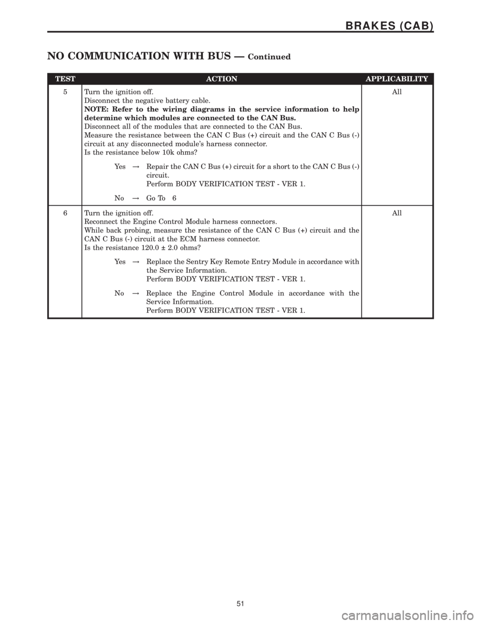
TEST ACTION APPLICABILITY
5 Turn the ignition off.
Disconnect the negative battery cable.
NOTE: Refer to the wiring diagrams in the service information to help
determine which modules are connected to the CAN Bus.
Disconnect all of the modules that are connected to the CAN Bus.
Measure the resistance between the CAN C Bus (+) circuit and the CAN C Bus (-)
circuit at any disconnected module's harness connector.
Is the resistance below 10k ohms?All
Ye s!Repair the CAN C Bus (+) circuit for a short to the CAN C Bus (-)
circuit.
Perform BODY VERIFICATION TEST - VER 1.
No!Go To 6
6 Turn the ignition off.
Reconnect the Engine Control Module harness connectors.
While back probing, measure the resistance of the CAN C Bus (+) circuit and the
CAN C Bus (-) circuit at the ECM harness connector.
Is the resistance 120.0 2.0 ohms?All
Ye s!Replace the Sentry Key Remote Entry Module in accordance with
the Service Information.
Perform BODY VERIFICATION TEST - VER 1.
No!Replace the Engine Control Module in accordance with the
Service Information.
Perform BODY VERIFICATION TEST - VER 1.
51
BRAKES (CAB)
NO COMMUNICATION WITH BUS ÐContinued
Page 373 of 2305
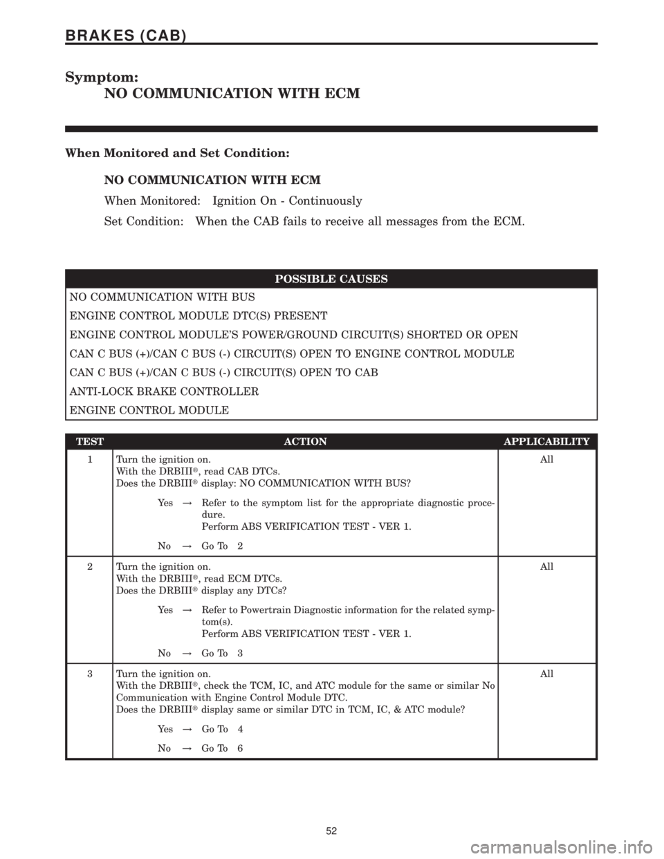
Symptom:
NO COMMUNICATION WITH ECM
When Monitored and Set Condition:
NO COMMUNICATION WITH ECM
When Monitored: Ignition On - Continuously
Set Condition: When the CAB fails to receive all messages from the ECM.
POSSIBLE CAUSES
NO COMMUNICATION WITH BUS
ENGINE CONTROL MODULE DTC(S) PRESENT
ENGINE CONTROL MODULE'S POWER/GROUND CIRCUIT(S) SHORTED OR OPEN
CAN C BUS (+)/CAN C BUS (-) CIRCUIT(S) OPEN TO ENGINE CONTROL MODULE
CAN C BUS (+)/CAN C BUS (-) CIRCUIT(S) OPEN TO CAB
ANTI-LOCK BRAKE CONTROLLER
ENGINE CONTROL MODULE
TEST ACTION APPLICABILITY
1 Turn the ignition on.
With the DRBIIIt, read CAB DTCs.
Does the DRBIIItdisplay: NO COMMUNICATION WITH BUS?All
Ye s!Refer to the symptom list for the appropriate diagnostic proce-
dure.
Perform ABS VERIFICATION TEST - VER 1.
No!Go To 2
2 Turn the ignition on.
With the DRBIIIt, read ECM DTCs.
Does the DRBIIItdisplay any DTCs?All
Ye s!Refer to Powertrain Diagnostic information for the related symp-
tom(s).
Perform ABS VERIFICATION TEST - VER 1.
No!Go To 3
3 Turn the ignition on.
With the DRBIIIt, check the TCM, IC, and ATC module for the same or similar No
Communication with Engine Control Module DTC.
Does the DRBIIItdisplay same or similar DTC in TCM, IC, & ATC module?All
Ye s!Go To 4
No!Go To 6
52
BRAKES (CAB)
Page 374 of 2305
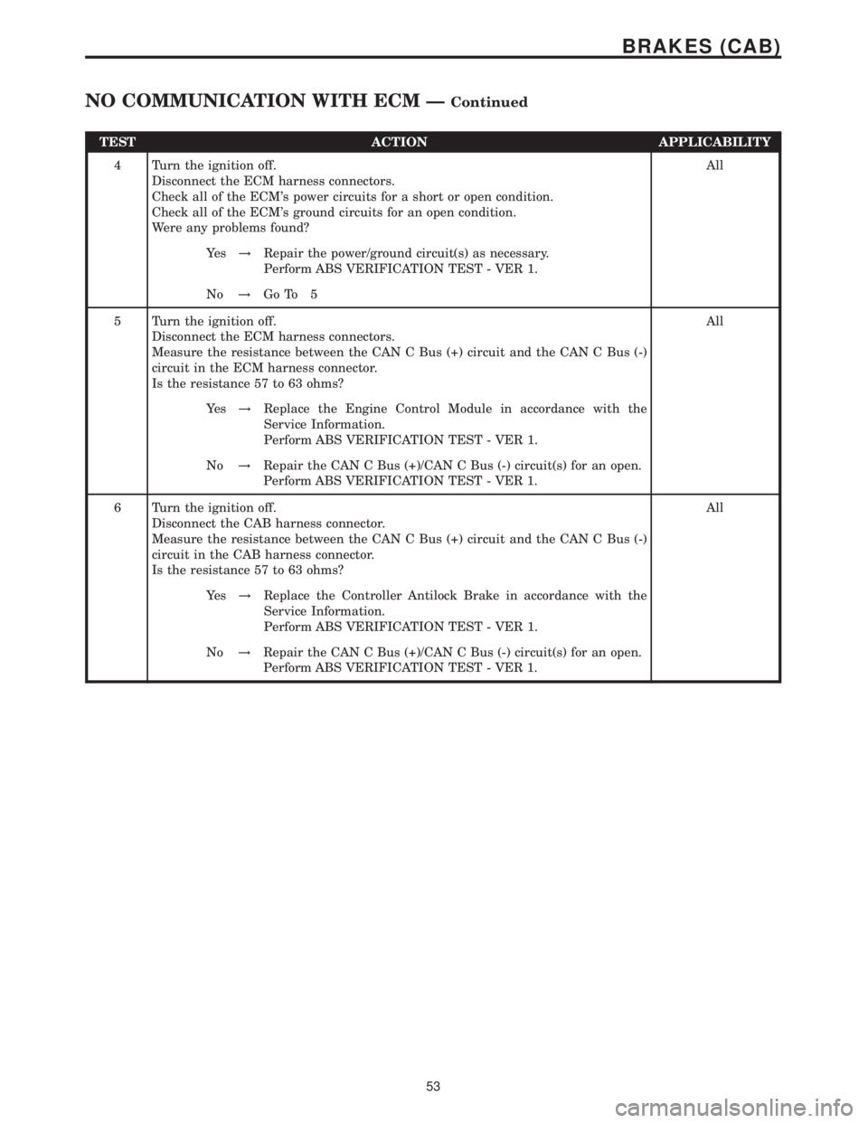
TEST ACTION APPLICABILITY
4 Turn the ignition off.
Disconnect the ECM harness connectors.
Check all of the ECM's power circuits for a short or open condition.
Check all of the ECM's ground circuits for an open condition.
Were any problems found?All
Ye s!Repair the power/ground circuit(s) as necessary.
Perform ABS VERIFICATION TEST - VER 1.
No!Go To 5
5 Turn the ignition off.
Disconnect the ECM harness connectors.
Measure the resistance between the CAN C Bus (+) circuit and the CAN C Bus (-)
circuit in the ECM harness connector.
Is the resistance 57 to 63 ohms?All
Ye s!Replace the Engine Control Module in accordance with the
Service Information.
Perform ABS VERIFICATION TEST - VER 1.
No!Repair the CAN C Bus (+)/CAN C Bus (-) circuit(s) for an open.
Perform ABS VERIFICATION TEST - VER 1.
6 Turn the ignition off.
Disconnect the CAB harness connector.
Measure the resistance between the CAN C Bus (+) circuit and the CAN C Bus (-)
circuit in the CAB harness connector.
Is the resistance 57 to 63 ohms?All
Ye s!Replace the Controller Antilock Brake in accordance with the
Service Information.
Perform ABS VERIFICATION TEST - VER 1.
No!Repair the CAN C Bus (+)/CAN C Bus (-) circuit(s) for an open.
Perform ABS VERIFICATION TEST - VER 1.
53
BRAKES (CAB)
NO COMMUNICATION WITH ECM ÐContinued
Page 375 of 2305
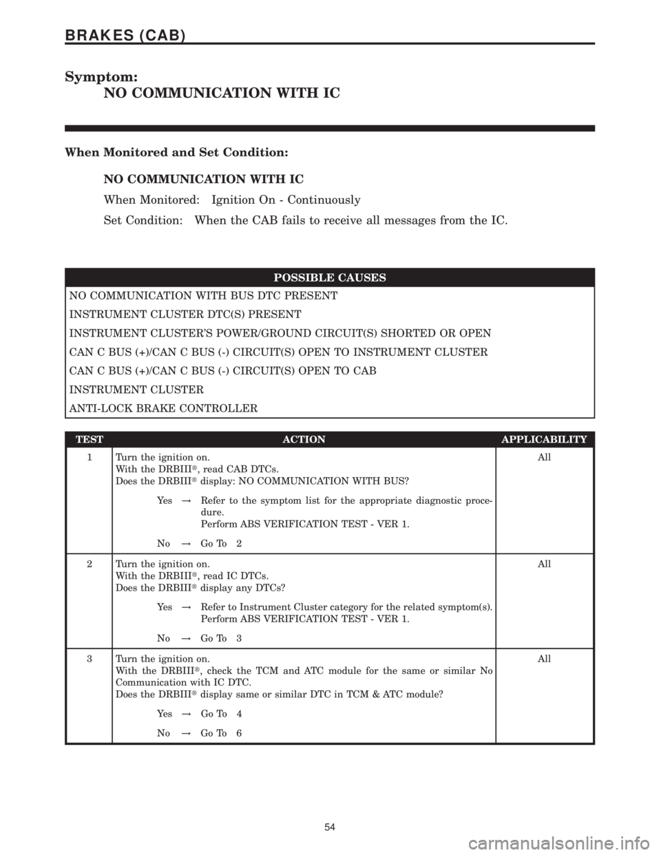
Symptom:
NO COMMUNICATION WITH IC
When Monitored and Set Condition:
NO COMMUNICATION WITH IC
When Monitored: Ignition On - Continuously
Set Condition: When the CAB fails to receive all messages from the IC.
POSSIBLE CAUSES
NO COMMUNICATION WITH BUS DTC PRESENT
INSTRUMENT CLUSTER DTC(S) PRESENT
INSTRUMENT CLUSTER'S POWER/GROUND CIRCUIT(S) SHORTED OR OPEN
CAN C BUS (+)/CAN C BUS (-) CIRCUIT(S) OPEN TO INSTRUMENT CLUSTER
CAN C BUS (+)/CAN C BUS (-) CIRCUIT(S) OPEN TO CAB
INSTRUMENT CLUSTER
ANTI-LOCK BRAKE CONTROLLER
TEST ACTION APPLICABILITY
1 Turn the ignition on.
With the DRBIIIt, read CAB DTCs.
Does the DRBIIItdisplay: NO COMMUNICATION WITH BUS?All
Ye s!Refer to the symptom list for the appropriate diagnostic proce-
dure.
Perform ABS VERIFICATION TEST - VER 1.
No!Go To 2
2 Turn the ignition on.
With the DRBIIIt, read IC DTCs.
Does the DRBIIItdisplay any DTCs?All
Ye s!Refer to Instrument Cluster category for the related symptom(s).
Perform ABS VERIFICATION TEST - VER 1.
No!Go To 3
3 Turn the ignition on.
With the DRBIIIt, check the TCM and ATC module for the same or similar No
Communication with IC DTC.
Does the DRBIIItdisplay same or similar DTC in TCM & ATC module?All
Ye s!Go To 4
No!Go To 6
54
BRAKES (CAB)
Page 376 of 2305
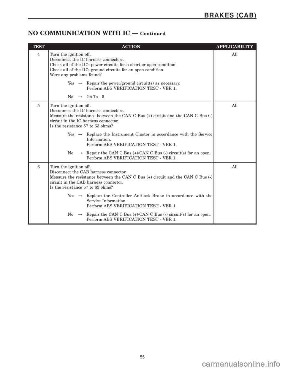
TEST ACTION APPLICABILITY
4 Turn the ignition off.
Disconnect the IC harness connectors.
Check all of the IC's power circuits for a short or open condition.
Check all of the IC's ground circuits for an open condition.
Were any problems found?All
Ye s!Repair the power/ground circuit(s) as necessary.
Perform ABS VERIFICATION TEST - VER 1.
No!Go To 5
5 Turn the ignition off.
Disconnect the IC harness connectors.
Measure the resistance between the CAN C Bus (+) circuit and the CAN C Bus (-)
circuit in the IC harness connector.
Is the resistance 57 to 63 ohms?All
Ye s!Replace the Instrument Cluster in accordance with the Service
Information.
Perform ABS VERIFICATION TEST - VER 1.
No!Repair the CAN C Bus (+)/CAN C Bus (-) circuit(s) for an open.
Perform ABS VERIFICATION TEST - VER 1.
6 Turn the ignition off.
Disconnect the CAB harness connector.
Measure the resistance between the CAN C Bus (+) circuit and the CAN C Bus (-)
circuit in the CAB harness connector.
Is the resistance 57 to 63 ohms?All
Ye s!Replace the Controller Antilock Brake in accordance with the
Service Information.
Perform ABS VERIFICATION TEST - VER 1.
No!Repair the CAN C Bus (+)/CAN C Bus (-) circuit(s) for an open.
Perform ABS VERIFICATION TEST - VER 1.
55
BRAKES (CAB)
NO COMMUNICATION WITH IC ÐContinued
Page 377 of 2305
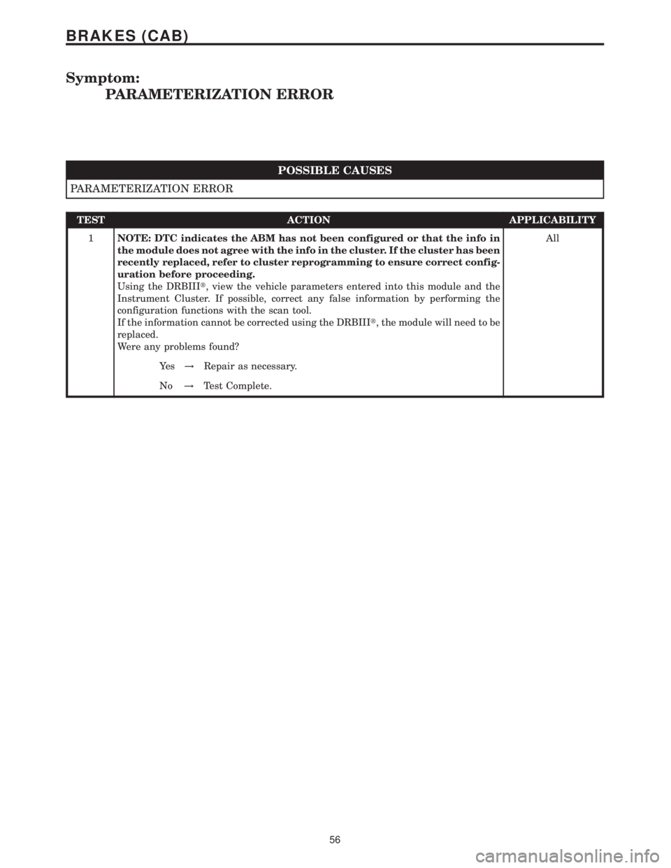
Symptom:
PARAMETERIZATION ERROR
POSSIBLE CAUSES
PARAMETERIZATION ERROR
TEST ACTION APPLICABILITY
1NOTE: DTC indicates the ABM has not been configured or that the info in
the module does not agree with the info in the cluster. If the cluster has been
recently replaced, refer to cluster reprogramming to ensure correct config-
uration before proceeding.
Using the DRBIIIt, view the vehicle parameters entered into this module and the
Instrument Cluster. If possible, correct any false information by performing the
configuration functions with the scan tool.
If the information cannot be corrected using the DRBIIIt, the module will need to be
replaced.
Were any problems found?All
Ye s!Repair as necessary.
No!Test Complete.
56
BRAKES (CAB)
Page 378 of 2305
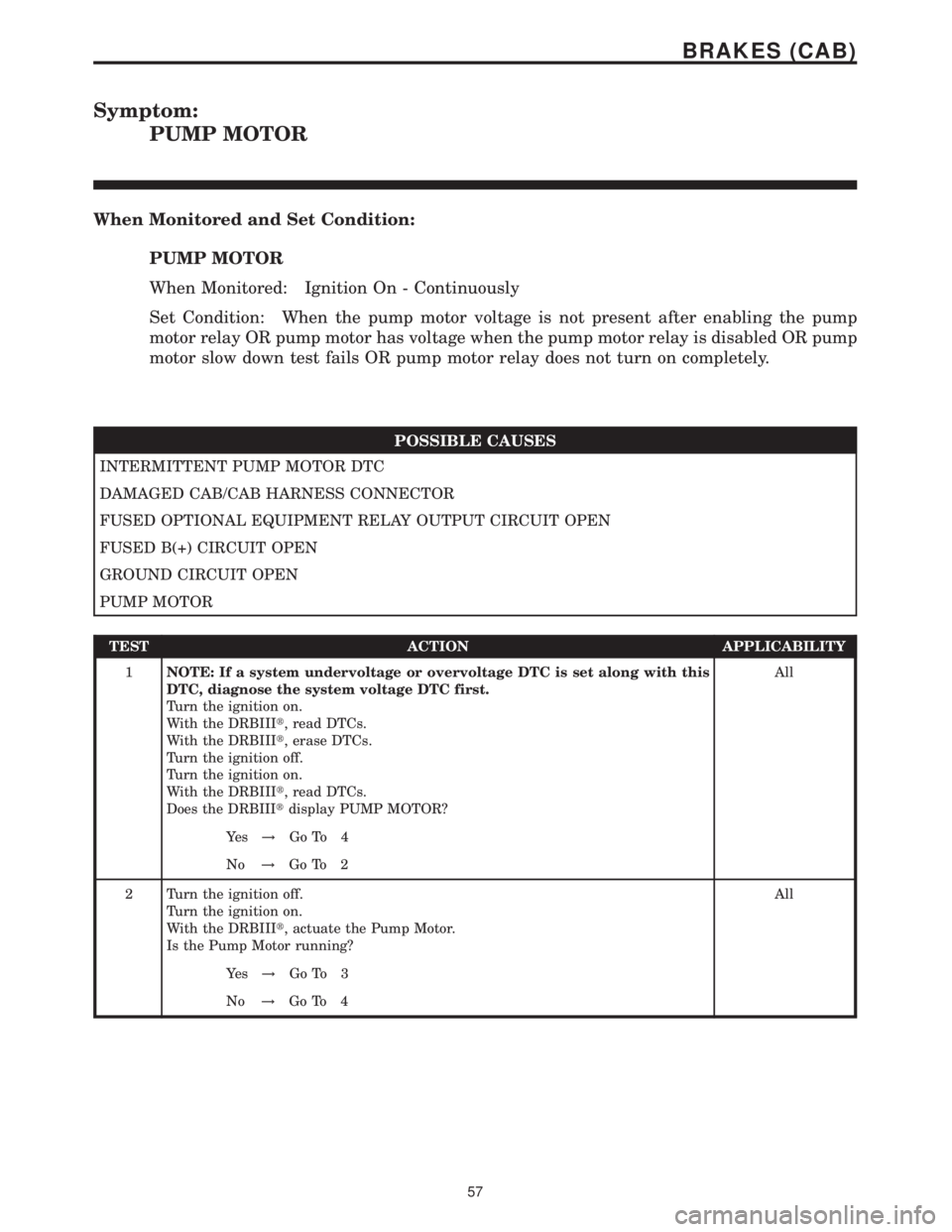
Symptom:
PUMP MOTOR
When Monitored and Set Condition:
PUMP MOTOR
When Monitored: Ignition On - Continuously
Set Condition: When the pump motor voltage is not present after enabling the pump
motor relay OR pump motor has voltage when the pump motor relay is disabled OR pump
motor slow down test fails OR pump motor relay does not turn on completely.
POSSIBLE CAUSES
INTERMITTENT PUMP MOTOR DTC
DAMAGED CAB/CAB HARNESS CONNECTOR
FUSED OPTIONAL EQUIPMENT RELAY OUTPUT CIRCUIT OPEN
FUSED B(+) CIRCUIT OPEN
GROUND CIRCUIT OPEN
PUMP MOTOR
TEST ACTION APPLICABILITY
1NOTE: If a system undervoltage or overvoltage DTC is set along with this
DTC, diagnose the system voltage DTC first.
Turn the ignition on.
With the DRBIIIt, read DTCs.
With the DRBIIIt, erase DTCs.
Turn the ignition off.
Turn the ignition on.
With the DRBIIIt, read DTCs.
Does the DRBIIItdisplay PUMP MOTOR?All
Ye s!Go To 4
No!Go To 2
2 Turn the ignition off.
Turn the ignition on.
With the DRBIIIt, actuate the Pump Motor.
Is the Pump Motor running?All
Ye s!Go To 3
No!Go To 4
57
BRAKES (CAB)
Page 379 of 2305
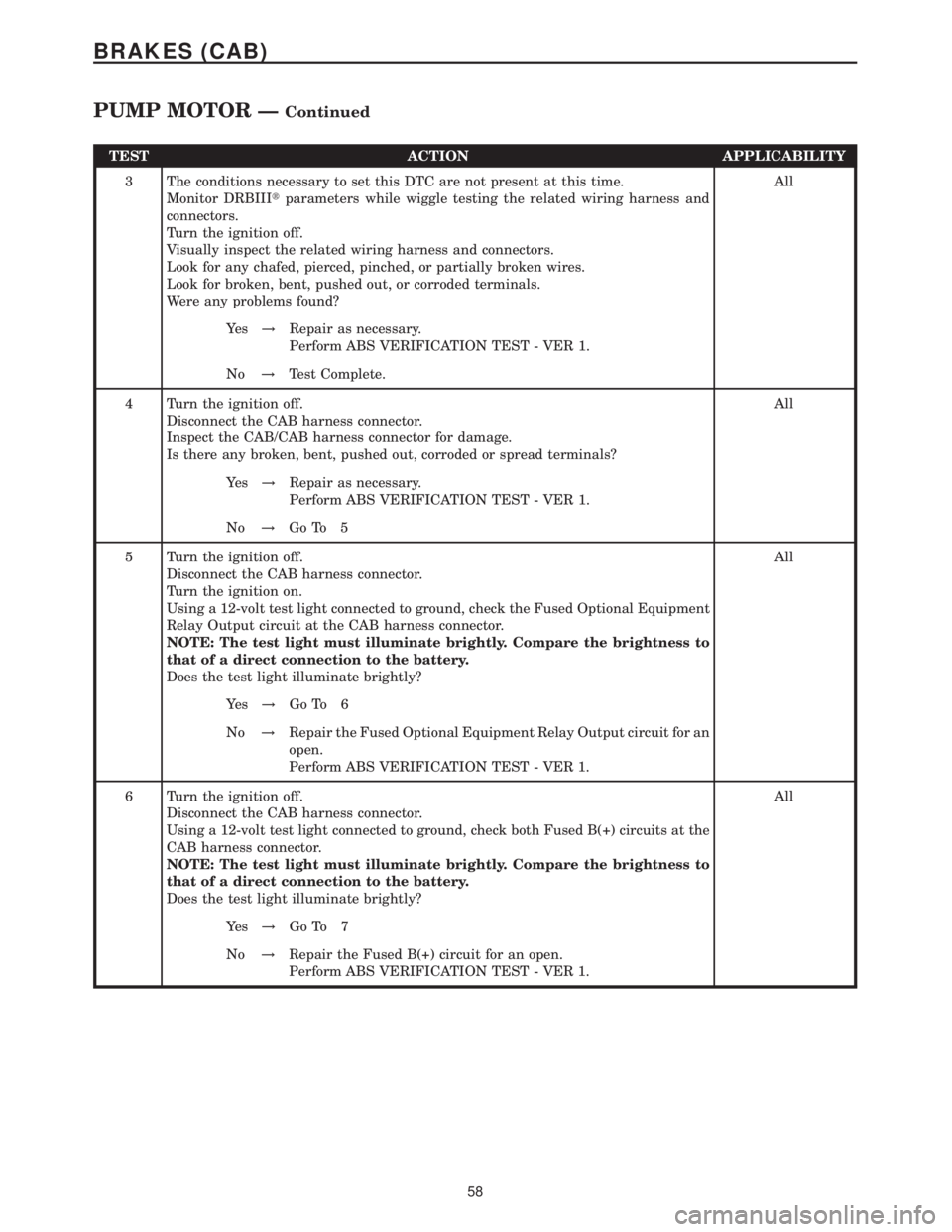
TEST ACTION APPLICABILITY
3 The conditions necessary to set this DTC are not present at this time.
Monitor DRBIIItparameters while wiggle testing the related wiring harness and
connectors.
Turn the ignition off.
Visually inspect the related wiring harness and connectors.
Look for any chafed, pierced, pinched, or partially broken wires.
Look for broken, bent, pushed out, or corroded terminals.
Were any problems found?All
Ye s!Repair as necessary.
Perform ABS VERIFICATION TEST - VER 1.
No!Test Complete.
4 Turn the ignition off.
Disconnect the CAB harness connector.
Inspect the CAB/CAB harness connector for damage.
Is there any broken, bent, pushed out, corroded or spread terminals?All
Ye s!Repair as necessary.
Perform ABS VERIFICATION TEST - VER 1.
No!Go To 5
5 Turn the ignition off.
Disconnect the CAB harness connector.
Turn the ignition on.
Using a 12-volt test light connected to ground, check the Fused Optional Equipment
Relay Output circuit at the CAB harness connector.
NOTE: The test light must illuminate brightly. Compare the brightness to
that of a direct connection to the battery.
Does the test light illuminate brightly?All
Ye s!Go To 6
No!Repair the Fused Optional Equipment Relay Output circuit for an
open.
Perform ABS VERIFICATION TEST - VER 1.
6 Turn the ignition off.
Disconnect the CAB harness connector.
Using a 12-volt test light connected to ground, check both Fused B(+) circuits at the
CAB harness connector.
NOTE: The test light must illuminate brightly. Compare the brightness to
that of a direct connection to the battery.
Does the test light illuminate brightly?All
Ye s!Go To 7
No!Repair the Fused B(+) circuit for an open.
Perform ABS VERIFICATION TEST - VER 1.
58
BRAKES (CAB)
PUMP MOTOR ÐContinued
Page 380 of 2305
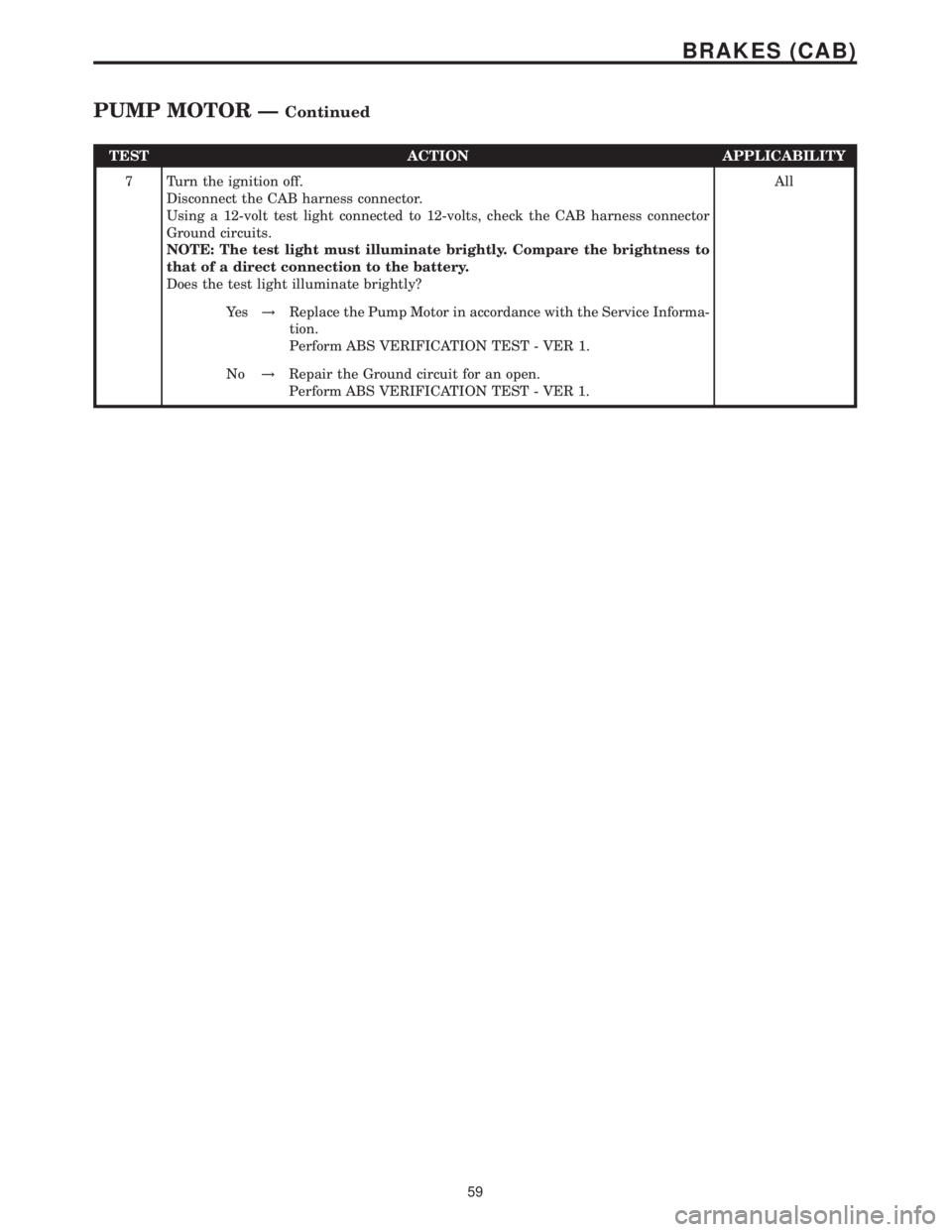
TEST ACTION APPLICABILITY
7 Turn the ignition off.
Disconnect the CAB harness connector.
Using a 12-volt test light connected to 12-volts, check the CAB harness connector
Ground circuits.
NOTE: The test light must illuminate brightly. Compare the brightness to
that of a direct connection to the battery.
Does the test light illuminate brightly?All
Ye s!Replace the Pump Motor in accordance with the Service Informa-
tion.
Perform ABS VERIFICATION TEST - VER 1.
No!Repair the Ground circuit for an open.
Perform ABS VERIFICATION TEST - VER 1.
59
BRAKES (CAB)
PUMP MOTOR ÐContinued