MERCEDES-BENZ SPRINTER 2006 Service Manual
Manufacturer: MERCEDES-BENZ, Model Year: 2006, Model line: SPRINTER, Model: MERCEDES-BENZ SPRINTER 2006Pages: 2305, PDF Size: 48.12 MB
Page 391 of 2305
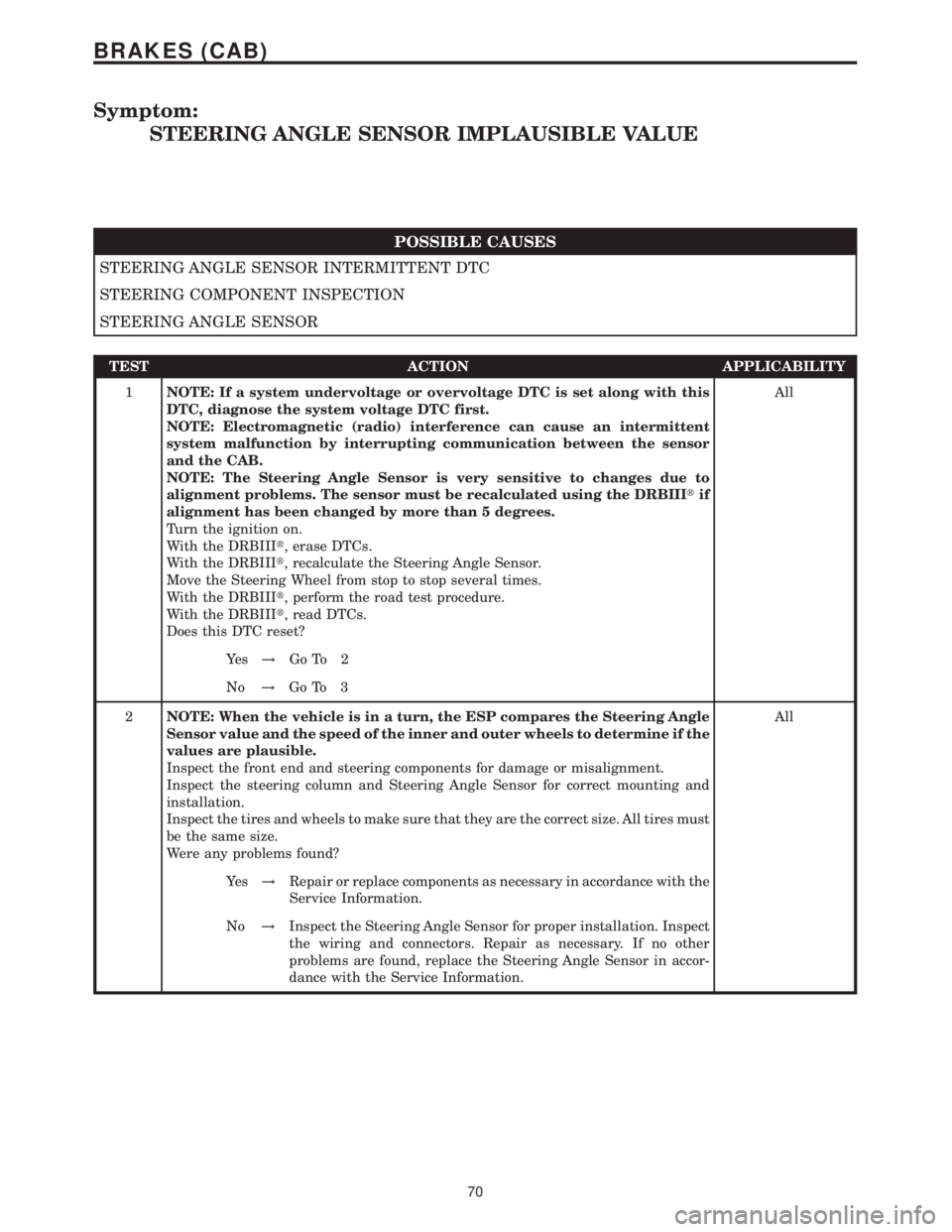
Symptom:
STEERING ANGLE SENSOR IMPLAUSIBLE VALUE
POSSIBLE CAUSES
STEERING ANGLE SENSOR INTERMITTENT DTC
STEERING COMPONENT INSPECTION
STEERING ANGLE SENSOR
TEST ACTION APPLICABILITY
1NOTE: If a system undervoltage or overvoltage DTC is set along with this
DTC, diagnose the system voltage DTC first.
NOTE: Electromagnetic (radio) interference can cause an intermittent
system malfunction by interrupting communication between the sensor
and the CAB.
NOTE: The Steering Angle Sensor is very sensitive to changes due to
alignment problems. The sensor must be recalculated using the DRBIIItif
alignment has been changed by more than 5 degrees.
Turn the ignition on.
With the DRBIIIt, erase DTCs.
With the DRBIIIt, recalculate the Steering Angle Sensor.
Move the Steering Wheel from stop to stop several times.
With the DRBIIIt, perform the road test procedure.
With the DRBIIIt, read DTCs.
Does this DTC reset?All
Ye s!Go To 2
No!Go To 3
2NOTE: When the vehicle is in a turn, the ESP compares the Steering Angle
Sensor value and the speed of the inner and outer wheels to determine if the
values are plausible.
Inspect the front end and steering components for damage or misalignment.
Inspect the steering column and Steering Angle Sensor for correct mounting and
installation.
Inspect the tires and wheels to make sure that they are the correct size. All tires must
be the same size.
Were any problems found?All
Ye s!Repair or replace components as necessary in accordance with the
Service Information.
No!Inspect the Steering Angle Sensor for proper installation. Inspect
the wiring and connectors. Repair as necessary. If no other
problems are found, replace the Steering Angle Sensor in accor-
dance with the Service Information.
70
BRAKES (CAB)
Page 392 of 2305
TEST ACTION APPLICABILITY
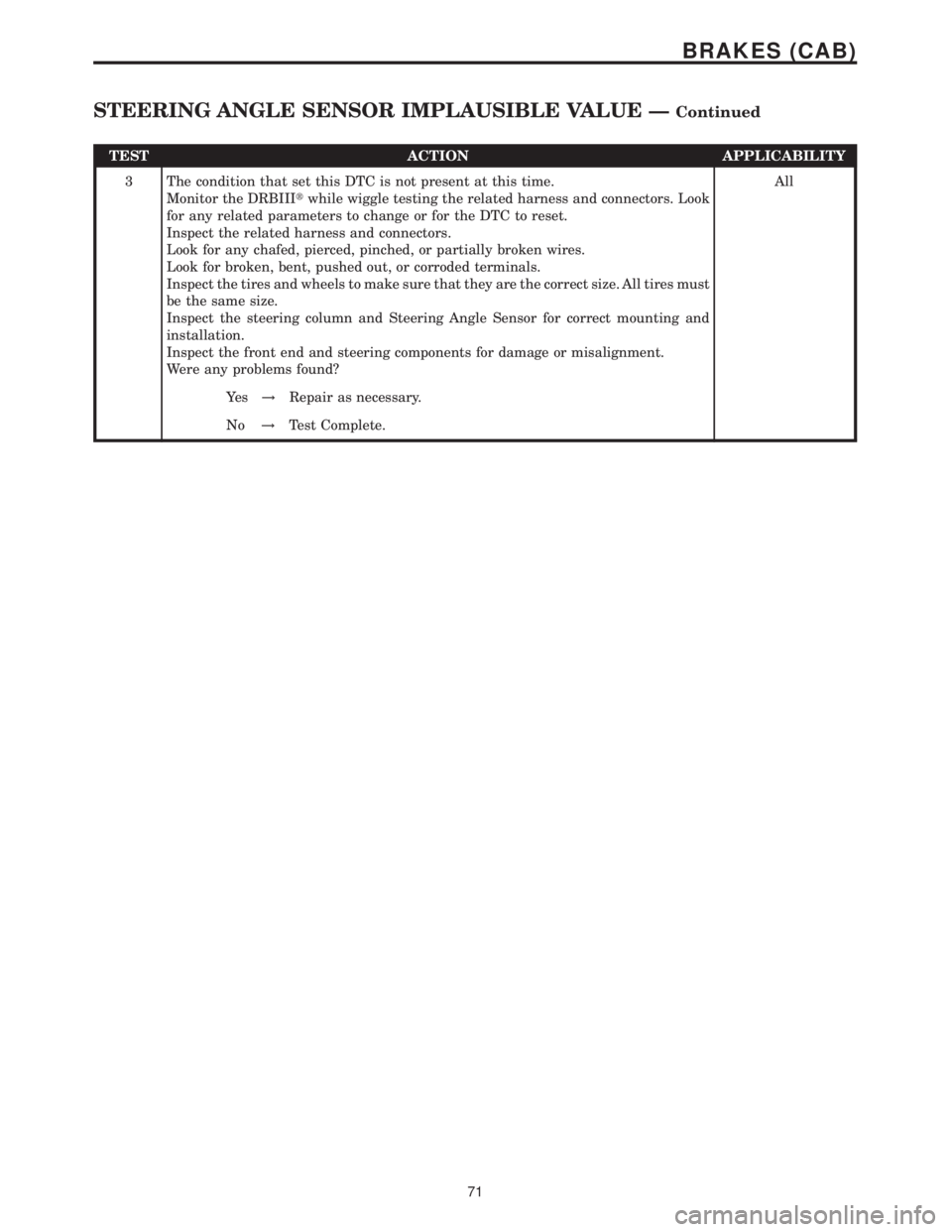
3 The condition that set this DTC is not present at this time.
Monitor the DRBIIItwhile wiggle testing the related harness and connectors. Look
for any related parameters to change or for the DTC to reset.
Inspect the related harness and connectors.
Look for any chafed, pierced, pinched, or partially broken wires.
Look for broken, bent, pushed out, or corroded terminals.
Inspect the tires and wheels to make sure that they are the correct size. All tires must
be the same size.
Inspect the steering column and Steering Angle Sensor for correct mounting and
installation.
Inspect the front end and steering components for damage or misalignment.
Were any problems found?All
Ye s!Repair as necessary.
No!Test Complete.
71
BRAKES (CAB)
STEERING ANGLE SENSOR IMPLAUSIBLE VALUE ÐContinued
Page 393 of 2305
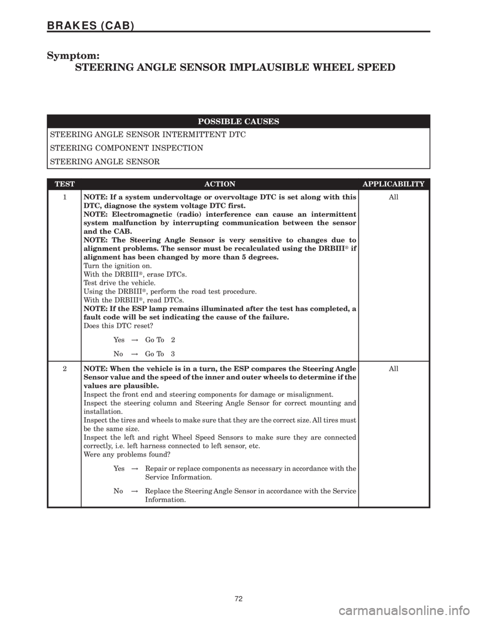
Symptom:
STEERING ANGLE SENSOR IMPLAUSIBLE WHEEL SPEED
POSSIBLE CAUSES
STEERING ANGLE SENSOR INTERMITTENT DTC
STEERING COMPONENT INSPECTION
STEERING ANGLE SENSOR
TEST ACTION APPLICABILITY
1NOTE: If a system undervoltage or overvoltage DTC is set along with this
DTC, diagnose the system voltage DTC first.
NOTE: Electromagnetic (radio) interference can cause an intermittent
system malfunction by interrupting communication between the sensor
and the CAB.
NOTE: The Steering Angle Sensor is very sensitive to changes due to
alignment problems. The sensor must be recalculated using the DRBIIItif
alignment has been changed by more than 5 degrees.
Turn the ignition on.
With the DRBIIIt, erase DTCs.
Test drive the vehicle.
Using the DRBIIIt, perform the road test procedure.
With the DRBIIIt, read DTCs.
NOTE: If the ESP lamp remains illuminated after the test has completed, a
fault code will be set indicating the cause of the failure.
Does this DTC reset?All
Ye s!Go To 2
No!Go To 3
2NOTE: When the vehicle is in a turn, the ESP compares the Steering Angle
Sensor value and the speed of the inner and outer wheels to determine if the
values are plausible.
Inspect the front end and steering components for damage or misalignment.
Inspect the steering column and Steering Angle Sensor for correct mounting and
installation.
Inspect the tires and wheels to make sure that they are the correct size. All tires must
be the same size.
Inspect the left and right Wheel Speed Sensors to make sure they are connected
correctly, i.e. left harness connected to left sensor, etc.
Were any problems found?All
Ye s!Repair or replace components as necessary in accordance with the
Service Information.
No!Replace the Steering Angle Sensor in accordance with the Service
Information.
72
BRAKES (CAB)
Page 394 of 2305
TEST ACTION APPLICABILITY
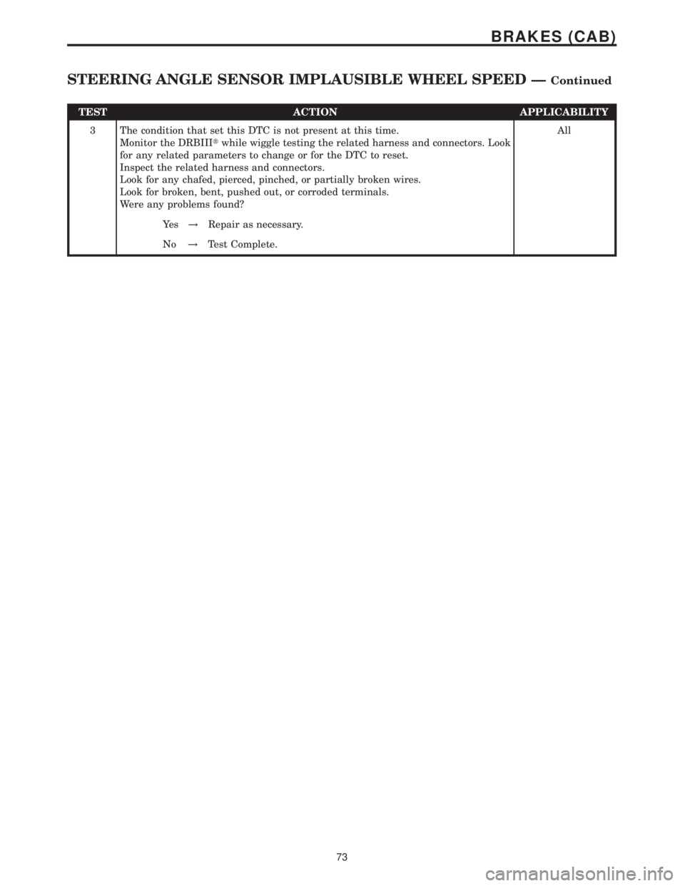
3 The condition that set this DTC is not present at this time.
Monitor the DRBIIItwhile wiggle testing the related harness and connectors. Look
for any related parameters to change or for the DTC to reset.
Inspect the related harness and connectors.
Look for any chafed, pierced, pinched, or partially broken wires.
Look for broken, bent, pushed out, or corroded terminals.
Were any problems found?All
Ye s!Repair as necessary.
No!Test Complete.
73
BRAKES (CAB)
STEERING ANGLE SENSOR IMPLAUSIBLE WHEEL SPEED ÐContinued
Page 395 of 2305
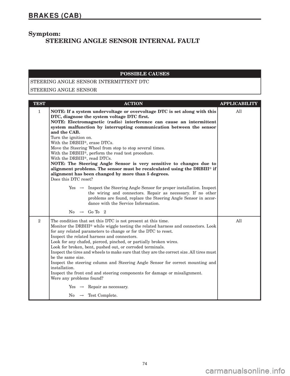
Symptom:
STEERING ANGLE SENSOR INTERNAL FAULT
POSSIBLE CAUSES
STEERING ANGLE SENSOR INTERMITTENT DTC
STEERING ANGLE SENSOR
TEST ACTION APPLICABILITY
1NOTE: If a system undervoltage or overvoltage DTC is set along with this
DTC, diagnose the system voltage DTC first.
NOTE: Electromagnetic (radio) interference can cause an intermittent
system malfunction by interrupting communication between the sensor
and the CAB.
Turn the ignition on.
With the DRBIIIt, erase DTCs.
Move the Steering Wheel from stop to stop several times.
With the DRBIIIt, perform the road test procedure.
With the DRBIIIt, read DTCs.
NOTE: The Steering Angle Sensor is very sensitive to changes due to
alignment problems. The sensor must be recalculated using the DRBIIItif
alignment has been changed by more than 5 degrees.
Does this DTC reset?All
Ye s!Inspect the Steering Angle Sensor for proper installation. Inspect
the wiring and connectors. Repair as necessary. If no other
problems are found, replace the Steering Angle Sensor in accor-
dance with the Service Information.
No!Go To 2
2 The condition that set this DTC is not present at this time.
Monitor the DRBIIItwhile wiggle testing the related harness and connectors. Look
for any related parameters to change or for the DTC to reset.
Inspect the related harness and connectors.
Look for any chafed, pierced, pinched, or partially broken wires.
Look for broken, bent, pushed out, or corroded terminals.
Inspect the tires and wheels to make sure that they are the correct size. All tires must
be the same size.
Inspect the steering column and Steering Angle Sensor for correct mounting and
installation.
Inspect the front end and steering components for damage or misalignment.
Were any problems found?All
Ye s!Repair as necessary.
No!Test Complete.
74
BRAKES (CAB)
Page 396 of 2305
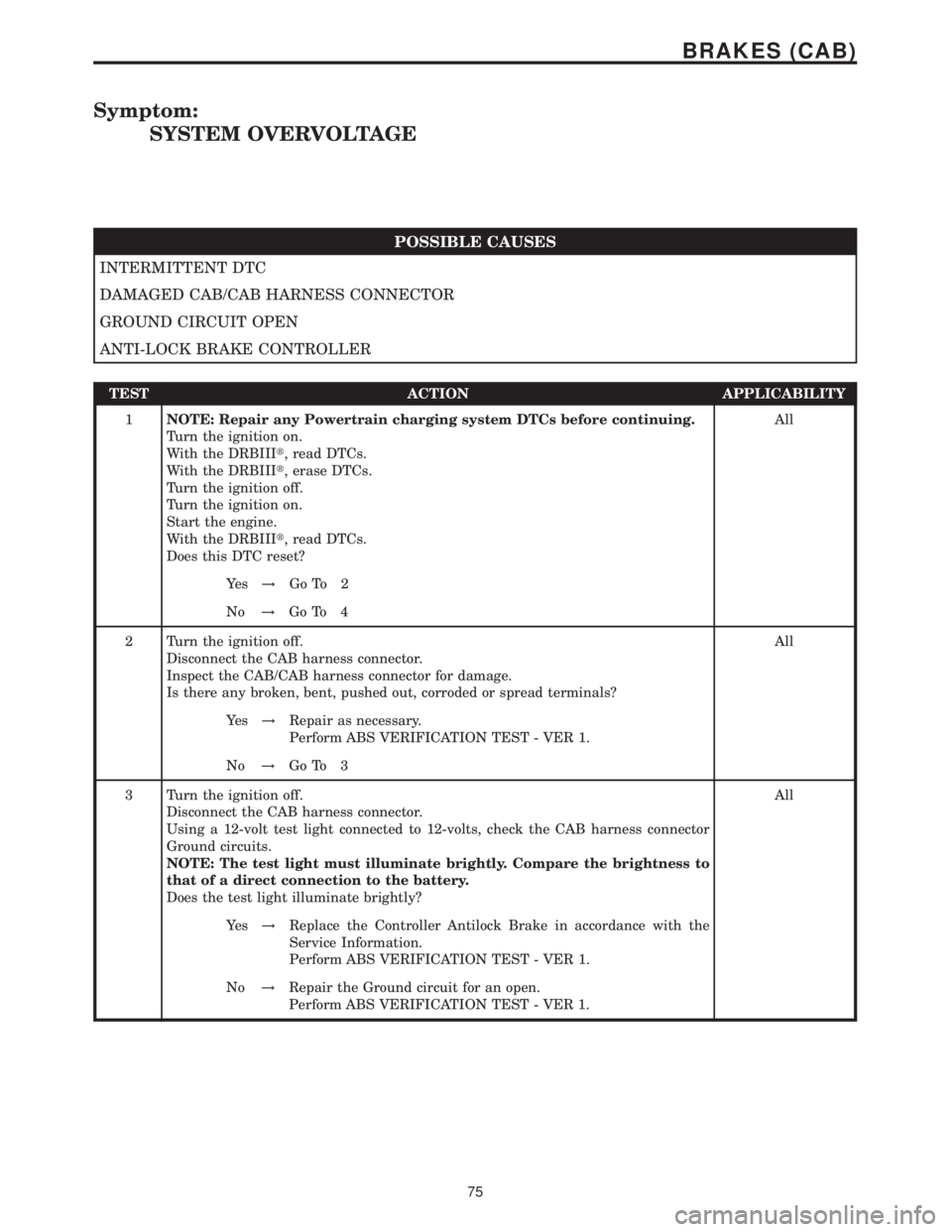
Symptom:
SYSTEM OVERVOLTAGE
POSSIBLE CAUSES
INTERMITTENT DTC
DAMAGED CAB/CAB HARNESS CONNECTOR
GROUND CIRCUIT OPEN
ANTI-LOCK BRAKE CONTROLLER
TEST ACTION APPLICABILITY
1NOTE: Repair any Powertrain charging system DTCs before continuing.
Turn the ignition on.
With the DRBIIIt, read DTCs.
With the DRBIIIt, erase DTCs.
Turn the ignition off.
Turn the ignition on.
Start the engine.
With the DRBIIIt, read DTCs.
Does this DTC reset?All
Ye s!Go To 2
No!Go To 4
2 Turn the ignition off.
Disconnect the CAB harness connector.
Inspect the CAB/CAB harness connector for damage.
Is there any broken, bent, pushed out, corroded or spread terminals?All
Ye s!Repair as necessary.
Perform ABS VERIFICATION TEST - VER 1.
No!Go To 3
3 Turn the ignition off.
Disconnect the CAB harness connector.
Using a 12-volt test light connected to 12-volts, check the CAB harness connector
Ground circuits.
NOTE: The test light must illuminate brightly. Compare the brightness to
that of a direct connection to the battery.
Does the test light illuminate brightly?All
Ye s!Replace the Controller Antilock Brake in accordance with the
Service Information.
Perform ABS VERIFICATION TEST - VER 1.
No!Repair the Ground circuit for an open.
Perform ABS VERIFICATION TEST - VER 1.
75
BRAKES (CAB)
Page 397 of 2305
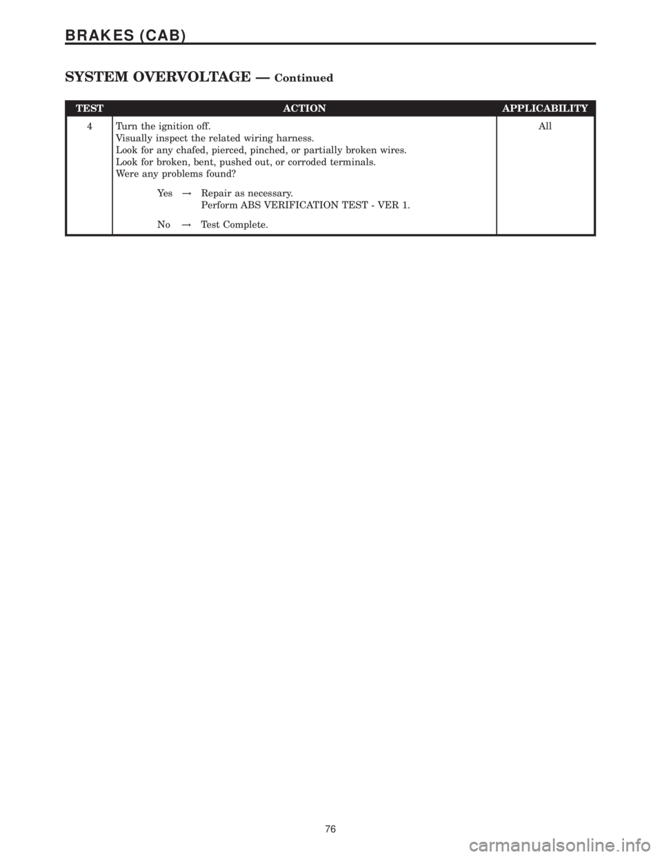
TEST ACTION APPLICABILITY
4 Turn the ignition off.
Visually inspect the related wiring harness.
Look for any chafed, pierced, pinched, or partially broken wires.
Look for broken, bent, pushed out, or corroded terminals.
Were any problems found?All
Ye s!Repair as necessary.
Perform ABS VERIFICATION TEST - VER 1.
No!Test Complete.
76
BRAKES (CAB)
SYSTEM OVERVOLTAGE ÐContinued
Page 398 of 2305
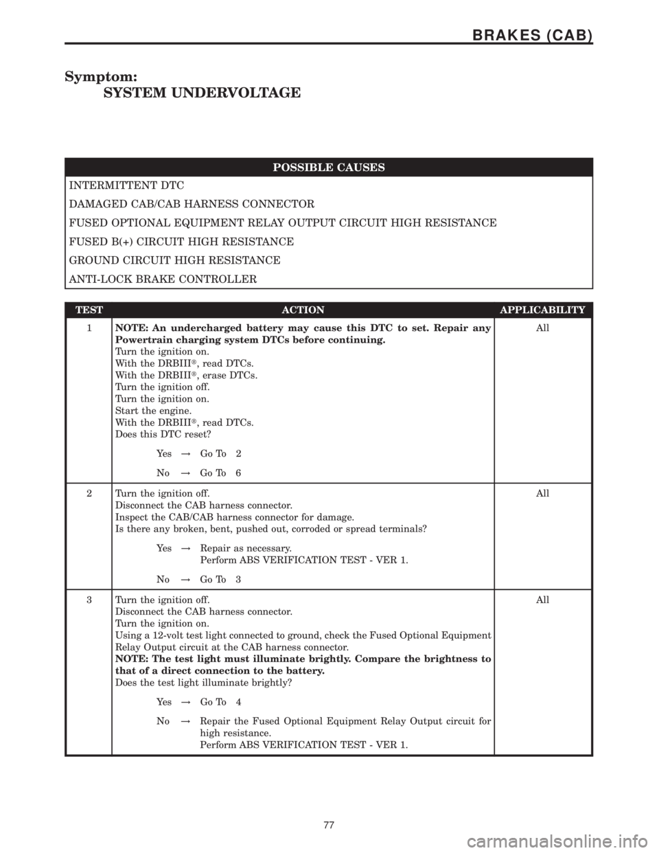
Symptom:
SYSTEM UNDERVOLTAGE
POSSIBLE CAUSES
INTERMITTENT DTC
DAMAGED CAB/CAB HARNESS CONNECTOR
FUSED OPTIONAL EQUIPMENT RELAY OUTPUT CIRCUIT HIGH RESISTANCE
FUSED B(+) CIRCUIT HIGH RESISTANCE
GROUND CIRCUIT HIGH RESISTANCE
ANTI-LOCK BRAKE CONTROLLER
TEST ACTION APPLICABILITY
1NOTE: An undercharged battery may cause this DTC to set. Repair any
Powertrain charging system DTCs before continuing.
Turn the ignition on.
With the DRBIIIt, read DTCs.
With the DRBIIIt, erase DTCs.
Turn the ignition off.
Turn the ignition on.
Start the engine.
With the DRBIIIt, read DTCs.
Does this DTC reset?All
Ye s!Go To 2
No!Go To 6
2 Turn the ignition off.
Disconnect the CAB harness connector.
Inspect the CAB/CAB harness connector for damage.
Is there any broken, bent, pushed out, corroded or spread terminals?All
Ye s!Repair as necessary.
Perform ABS VERIFICATION TEST - VER 1.
No!Go To 3
3 Turn the ignition off.
Disconnect the CAB harness connector.
Turn the ignition on.
Using a 12-volt test light connected to ground, check the Fused Optional Equipment
Relay Output circuit at the CAB harness connector.
NOTE: The test light must illuminate brightly. Compare the brightness to
that of a direct connection to the battery.
Does the test light illuminate brightly?All
Ye s!Go To 4
No!Repair the Fused Optional Equipment Relay Output circuit for
high resistance.
Perform ABS VERIFICATION TEST - VER 1.
77
BRAKES (CAB)
Page 399 of 2305
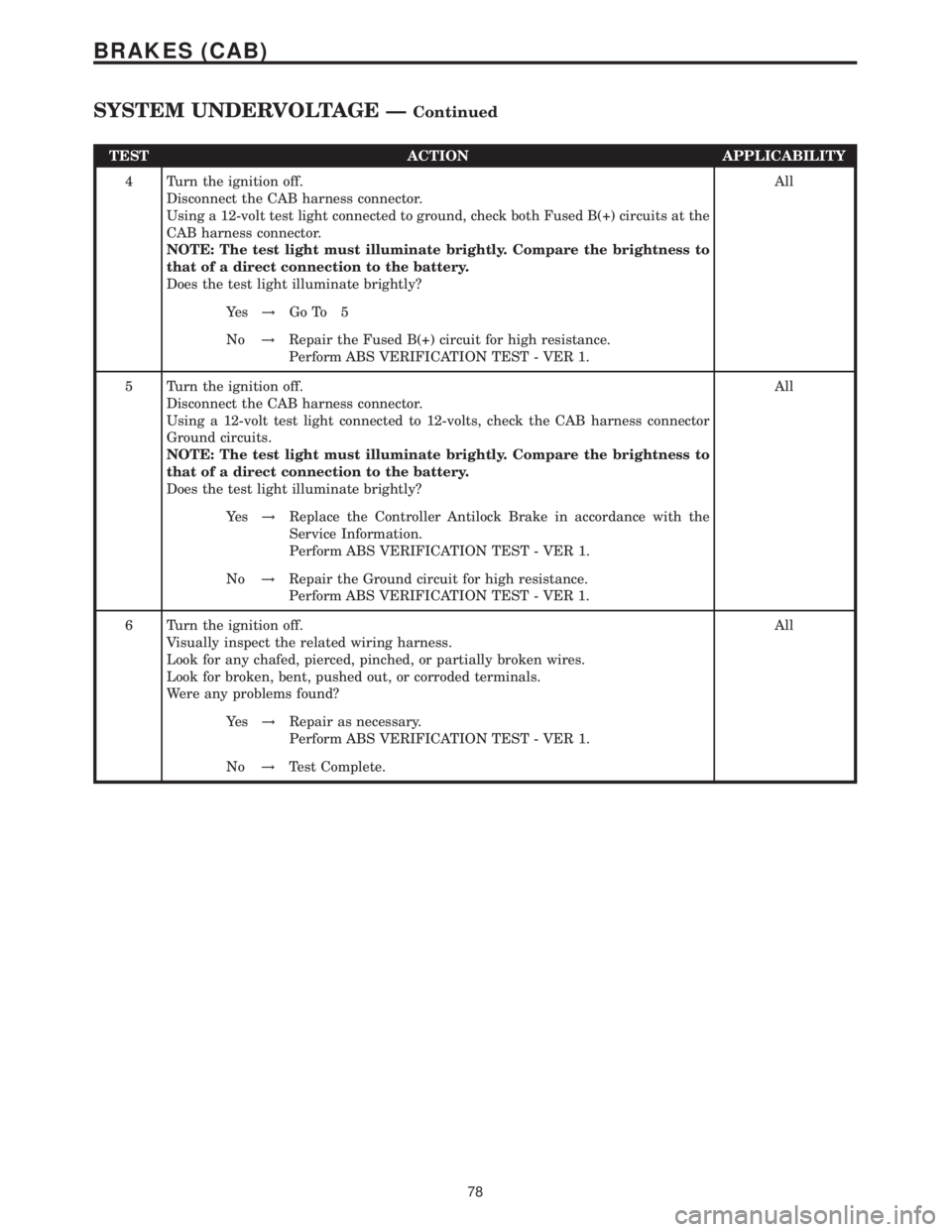
TEST ACTION APPLICABILITY
4 Turn the ignition off.
Disconnect the CAB harness connector.
Using a 12-volt test light connected to ground, check both Fused B(+) circuits at the
CAB harness connector.
NOTE: The test light must illuminate brightly. Compare the brightness to
that of a direct connection to the battery.
Does the test light illuminate brightly?All
Ye s!Go To 5
No!Repair the Fused B(+) circuit for high resistance.
Perform ABS VERIFICATION TEST - VER 1.
5 Turn the ignition off.
Disconnect the CAB harness connector.
Using a 12-volt test light connected to 12-volts, check the CAB harness connector
Ground circuits.
NOTE: The test light must illuminate brightly. Compare the brightness to
that of a direct connection to the battery.
Does the test light illuminate brightly?All
Ye s!Replace the Controller Antilock Brake in accordance with the
Service Information.
Perform ABS VERIFICATION TEST - VER 1.
No!Repair the Ground circuit for high resistance.
Perform ABS VERIFICATION TEST - VER 1.
6 Turn the ignition off.
Visually inspect the related wiring harness.
Look for any chafed, pierced, pinched, or partially broken wires.
Look for broken, bent, pushed out, or corroded terminals.
Were any problems found?All
Ye s!Repair as necessary.
Perform ABS VERIFICATION TEST - VER 1.
No!Test Complete.
78
BRAKES (CAB)
SYSTEM UNDERVOLTAGE ÐContinued
Page 400 of 2305
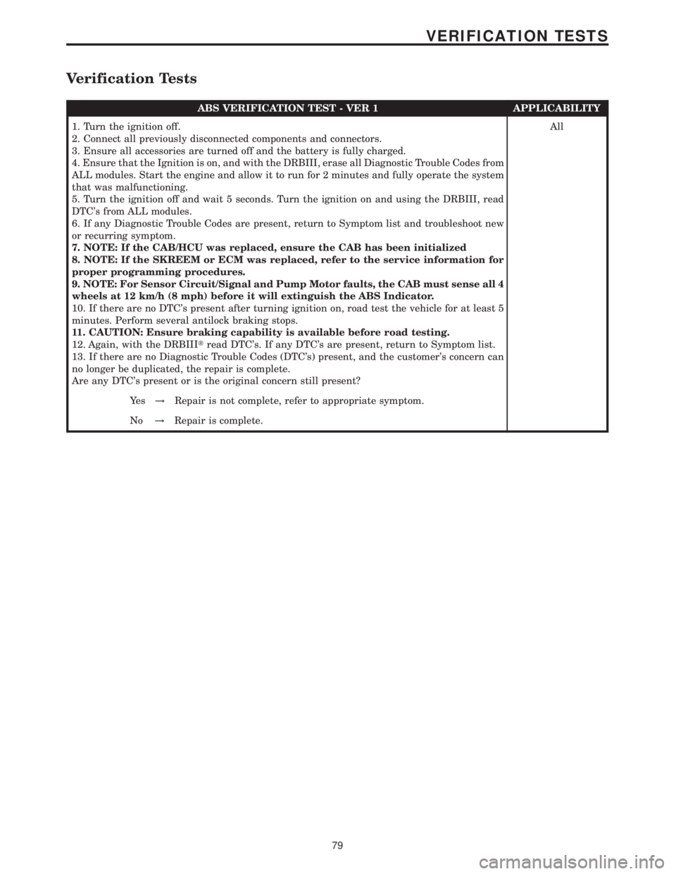
Verification Tests
ABS VERIFICATION TEST - VER 1 APPLICABILITY
1. Turn the ignition off.
2. Connect all previously disconnected components and connectors.
3. Ensure all accessories are turned off and the battery is fully charged.
4. Ensure that the Ignition is on, and with the DRBIII, erase all Diagnostic Trouble Codes from
ALL modules. Start the engine and allow it to run for 2 minutes and fully operate the system
that was malfunctioning.
5. Turn the ignition off and wait 5 seconds. Turn the ignition on and using the DRBIII, read
DTC's from ALL modules.
6. If any Diagnostic Trouble Codes are present, return to Symptom list and troubleshoot new
or recurring symptom.
7. NOTE: If the CAB/HCU was replaced, ensure the CAB has been initialized
8. NOTE: If the SKREEM or ECM was replaced, refer to the service information for
proper programming procedures.
9. NOTE: For Sensor Circuit/Signal and Pump Motor faults, the CAB must sense all 4
wheels at 12 km/h (8 mph) before it will extinguish the ABS Indicator.
10. If there are no DTC's present after turning ignition on, road test the vehicle for at least 5
minutes. Perform several antilock braking stops.
11. CAUTION: Ensure braking capability is available before road testing.
12. Again, with the DRBIIItread DTC's. If any DTC's are present, return to Symptom list.
13. If there are no Diagnostic Trouble Codes (DTC's) present, and the customer's concern can
no longer be duplicated, the repair is complete.
Are any DTC's present or is the original concern still present?All
Ye s!Repair is not complete, refer to appropriate symptom.
No!Repair is complete.
79
VERIFICATION TESTS