MINI COOPER 2003 Repair Manual
Manufacturer: MINI, Model Year: 2003, Model line: COOPER, Model: MINI COOPER 2003Pages: 148, PDF Size: 3.17 MB
Page 61 of 148

59
OVERVIEW REPAIRS OPERATIONCONTROLS DATA INDEX
FUEL GAUGE COOLANT TEMPERATURE GAUGE In the navigation system
Please also comply with the instruc-
tions in the previous section.<
If the indicator light 1 changes from orange
to red, there are approx. 2.1 gallons /
8 liters of fuel in the tank.
Low temperatureThe needle is at the bottom or on the right
of the range.
The engine is still cold. Drive at moderate
engine and vehicle speeds.Center positionNormal operating temperature of the
engine.High temperatureAs soon as there is a deviation from the
center position upwards or to the left:
Drive moderately and at low engine speed.
If necessary, switch off the engine and
allow it to cool down.
Checking coolant level, see page 96.
1 Red indicator lamp When you switch on the ignition, warning
lamp 1 comes on briefly to confirm that the
system is operational.
Lights up while driving:
Engine is too hot. Switch off the engine
immediately and allow it to cool down.Navigation system option
Coolant temperature warning
lamp in tachometer lights up while
driving:
Engine is too hot. Switch off the engine
immediately and allow it to cool down.
ba.book Seite 59 Montag, 5. August 2002 8:09 20
ProCarManuals.com
Page 62 of 148

60
SERVICE INTERVAL DISPLAY CLOCK COMPUTER
*
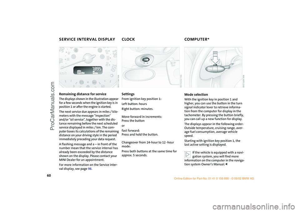
Remaining distance for service
The displays shown in the illustration appear
for a few seconds when the ignition key is in
position 1 or after the engine is started.
The next service due appears in miles / kilo-
meters with the message "inspection"
and/or "oil service", together with the dis-
tance remaining before the next scheduled
service displayed in miles / km. The com-
puter bases its calculations of the remaining
distance on your driving style in the period
immediately preceding your data request.
A flashing message and a – in front of the
number mean that the service interval has
already been exceeded by the distance
shown on the display. Please contact your
MINI Dealer for an appointment.
For more information on the Service inter-
val display, see page 98.
SettingsFrom ignition key position 1:
Left button: hours
Right button: minutes.
Move forward in increments:
Press the button
or
fast forward:
Press and hold the button.
Changeover from 24-hour to 12 -hour
mode:
Press both buttons at the same time for
approx. 5 seconds.
Mode selectionWith the ignition key in position 1 and
higher, you can use the button in the turn
signal indicator lever to retrieve informa-
tion from the computer for display in the
tachometer. By pressing the button briefly,
you can call up a new function for display.
The displays appear in the following order:
Outside temperature, cruising range, aver-
age fuel consumption, average vehicle
speed.
Starting with ignition key position 1, the
last active setting is displayed.
If the vehicle is equipped with a navi-
gation system, you will find more
information on the computer in the naviga-
tion system Owner‘s Manual.<
ba.book Seite 60 Montag, 5. August 2002 8:09 20
ProCarManuals.com
Page 63 of 148

61
OVERVIEW REPAIRS OPERATIONCONTROLS DATA INDEX
COMPUTER
*
Outside temperature
If the vehicle is equipped with a tachome-
ter, but not with a computer, the tempera-
ture is always displayed.
You can have the units 6 or 7 set
by your MINI Dealer.<
Range The computer bases its calculations for the
cruising range on the driving style and on
the remaining fuel in the tank.
If the range displayed is less than
35 miles / 50 km be sure to refuel,
otherwise engine functions are not guaran-
teed and damage could occur.<
Average speed –
Average fuel consumption Press the button in the turn signal indicator
lever for a longer period.
The displayed average speed value and
consumption value are recalculated.
Any time spent when the vehicle is station-
ary and the engine is shut off is ignored for
the calculation.
You can have other units set by your
MINI Dealer.<
ba.book Seite 61 Montag, 5. August 2002 8:09 20
ProCarManuals.com
Page 64 of 148

62
AUTOMATIC STABILITY CONTROL PLUS TRACTION (ASC+T)
*
The concept
This system optimizes vehicle stability and
traction, especially when just starting off,
when accelerating or when cornering.
ASC+T recognizes the danger present in
traction loss and will increase driving sta-
bility and traction by reducing the engine's
output and, if necessary, by applying the
brakes to the front wheels. ASC+T is opera-
tional each time you start the engine.
The laws of physics cannot be
repealed, even with ASC+T. An appro-
priate driving style always remains the
responsibility of the driver. Avoid using the
additional safety margin provided by the
system as an excuse for taking unnecessary
risks.
Do not make any modifications to the
ASC+T system. Allow only authorized tech-
nicians to perform service procedures on
the ASC+T.<
Indicator lamp
The indicator lamp on the instru-
ment cluster will go out shortly
after the ignition has been
switched on, see pages 16, 17.
If the indicator lamp flashes:
ASC+T controls the drive and braking
forces.
If the indicator lamp fails to go out
after the engine is started, or if it
comes on during normal driving and stays
on:
The system is defective or was turned off
using the button.
The described stabilizing operations are no
longer available.
You can, however, drive the vehicle nor-
mally without ASC+T.
In the event of a malfunction, please see
your MINI Dealer, see pages 16, 17.<
Switch off the ASC+TBriefly press the switch.
The indicator lamp stays lit.
When driving with snow chains or to "rock
free" in snow, it can be helpful to switch off
the ASC+T for a brief period.
To maintain vehicle stability, always
drive with the ASC+T switched on
whenever possible.
ba.book Seite 62 Montag, 5. August 2002 8:09 20
ProCarManuals.com
Page 65 of 148

63
OVERVIEW REPAIRS OPERATIONCONTROLS DATA INDEX
DYNAMIC STABILITY CONTROL (DSC)
*
The concept
This system maintains driving stability
even in critical driving situations.
The system optimizes vehicle stability dur-
ing acceleration and when starting from a
full stop, as well as optimizing traction. In
addition, it recognizes unstable vehicle
conditions, such as understeering or over-
steering, and, as far as is possible within
the laws of physics, helps keep the vehicle
on a steady course by reducing the rpms
and by brake applications to the individual
wheels.
The DSC is operational every time you start
the engine. DSC contains the functions
Antilock Brake System (ABS), Electronic
Brake Force Distribution (EBD), and ASC+T.
The laws of physics cannot be
repealed, even with DSC. An appro-
priate driving style always remains the
responsibility of the driver. We therefore
urge you to avoid using the additional
safety margin of the system as an excuse
for taking risks.
Do not make any modifications to the DSC
system. Allow only authorized technicians
to perform service procedures on the
DSC.<
Indicator lamp
The indicator lamp on the instru-
ment cluster will go out shortly
after the ignition has been
switched on, see pages 16, 17.
If the indicator lamp flashes:
DSC controls the drive and braking forces.
If the indicator lamp fails to go out
after the engine is started, or if it
comes on during normal driving and stays
on:
The system is defective or was turned off
using the button.
The described stabilizing operations are no
longer available.
The vehicle will remain completely opera-
tional, however, without DSC.
In the event of a malfunction, please see
your MINI Dealer, see pages 16, 17.<
To switch off the DSCBriefly press the switch.
The indicator lamp stays lit.
When driving with snow chains, it may be
effective to switch off the DSC for a brief
period.
To maintain stability, always drive
with the DSC switched on whenever
possible.
ba.book Seite 63 Montag, 5. August 2002 8:09 20
ProCarManuals.com
Page 66 of 148

64
FLAT TIRE MONITORThe conceptThe tire inflation pressure is determined
from the signals of the ABS sensors.
The system provides an alert whenever the
tire inflation pressure drops below the
pressure in any other tire. RequirementSo that the system can "familiarize" itself
with the correct inflation pressure, please
do the following:
1. Check the tire inflation pressure in all
tires
2. Compare them with the inflation pres-
sure table, see page 86, and adjust the
pressures if necessary
3. Initialize the system.
Check the tire inflation pressure reg-
ularly and correct it if necessary, see
page 85.<
Flat tire
The indicator lamp in the instru-
ment cluster informs you by flash-
ing when the tire inflation pressure
of a tire deviates from the "learned" values.
In addition, an acoustic signal is sounded.
>Vehicles with Run Flat tires, see notes on
pages 85, 88, 116
>Vehicles with normal tires, see notes on
pages 85, 112.
The Flat Tire Monitor cannot alert you
to severe and sudden tire damage
caused by external factors. Another factor
which the Flat Tire Monitor does not recog-
nize is the balanced and very gradual pres-
sure loss that takes place in all tires over an
extended period of time.<
MalfunctionsAs long as there is still a malfunction, the
yellow indicator lamp on the instrument
cluster will stay lit up.
The indicator lamp also lights up in the
event of a system malfunction.
Please contact your MINI Dealer in these
cases.
ba.book Seite 64 Montag, 5. August 2002 8:09 20
ProCarManuals.com
Page 67 of 148

65
OVERVIEW REPAIRS OPERATIONCONTROLS DATA INDEX
FLAT TIRE MONITORInitializing the systemOnly initialize the system if the inflation
pressure has been corrected or changed,
e.g. after a tire change.
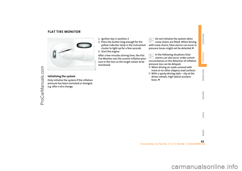
1. Ignition key in position 2
2. Press the button long enough for the
yellow indicator lamp in the instrument
cluster to light up for a few seconds
3. Start the engine.
After a few minutes driving time, the Flat
Tire Monitor sets the current inflation pres-
sure in the tires as the target values to be
monitored.Do not initialize the system when
snow chains are fitted. When driving
with snow chains, false alarms can occur or
pressure losses might not be detected.<
In the following situations false
alarms can also occur under certain
circumstances or the detection of inflation
pressure loss can be delayed:
>When driving on roads covered with
snow or on other slippery road surfaces
>With a sporty driving style – slip at the
driven wheels, high lateral accelera-
tions.<
ba.book Seite 65 Montag, 5. August 2002 8:09 20
ProCarManuals.com
Page 68 of 148

66
PARK DISTANCE CONTROL (PDC)*The conceptThe PDC assists you when you back into a
parking space. A signal tone tells you the
current distance to an object behind your
vehicle. To do this, four ultrasonic sensors
in the rear bumper measure the distance to
the nearest object.
The sensors on each side have a range of
approx. 2 ft / 60 cm, the middle sensors
one of approx. 5 ft / 1.5 m.
The system starts to operate automatically
about one second after you select reverse
with the ignition key in position 2.
Wait for this one second before you
drive backwards.<
PDC is deactivated when you shift away
from Reverse.
You can have a signal tone set by your
MINI Dealer as a confirmation that
PDC has been activated.<
Acoustical signalsThe distance to an object is indicated by a
tone sounding at intervals. As the distance
between vehicle and object decreases, the
intervals between the tones become
shorter. A continuous tone indicates the
presence of an object less than 8 in / 20 cm
away.
The warning signal is canceled after
approx. three seconds if the distance to the
object remains constant during this time,
for instance if you are moving parallel to a
wall.
System malfunctions will be indicated by a
continuous high-pitched tone when the
system is activated the first time. Please
have your MINI Dealer resolve the problem.Volume controlThe volume of the Park Distance Control
signal can be adjusted from level 1 – soft –
to level 6 – loud.
The volume can be set by your MINI
Dealer.<
Even with PDC, final responsibility for
estimating the distance between the
vehicle and any objects always remains
with the driver.
Even when sensors are involved, there is a
blind spot in which objects cannot be de-
tected. Recognition of some objects can be
beyond the limits of physical ultrasonic
measurement, for example with towing
bars or hitches or with thin or wedge-
shaped objects. Moreover, low objects that
have already been detected – such as a curb
edge – can disappear out of the range of
the sensors before a continuous tone
sounds.
Loud sources of sound outside and inside
your vehicle can drown the PDC signal
tone.<
Keep the sensors clean and free of ice
or snow in order to ensure that they
will continue to operate effectively.
Do not apply high pressure spray to the
sensors for a prolonged period of time.
Always maintain a distance which is
greater than 4 in / 10 cm.<
ba.book Seite 66 Montag, 5. August 2002 8:09 20
ProCarManuals.com
Page 69 of 148

67
OVERVIEW REPAIRS OPERATIONCONTROLS DATA INDEX
AIR CONDITIONING SYSTEM
*
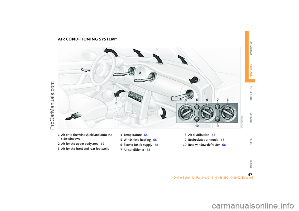
1Air onto the windshield and onto the
side windows
2Air for the upper body area69
3Air for the front and rear footwells4Temperature68
5Windshield heating68
6Blower for air supply68
7Air conditioner688Air distribution68
9Recirculated air mode68
10 Rear window defroster68
ba.book Seite 67 Montag, 5. August 2002 8:09 20
ProCarManuals.com
Page 70 of 148

68
AIR CONDITIONING SYSTEM
*
Air supply
You can select blower speeds
from 1 to 4. Position 0: fan is
turned off. The button for recir-
culated air mode fully blocks the
supply of air from outside.
Heating and ventilation operate as of
position 1.
Temperature
Turn to the right – red – to
increase the temperature of the
passenger compartment.
Rapid heating: turn to the
extreme right. Then select a pleasant inte-
rior temperature.
Air distribution
Air distribution in upper body
region , upper body region
and footwell , footwell ,
footwell and windows , and
windows .
All intermediate positions are possible, see
illustration and overview on page 67.
Rear window defroster
Rear window defroster switched
on:
Indicator lamp lights up.
As long as the indicator lamp is lit, the
heating operates at high power output –
rapid defrosting.
Indicator lamp goes out.
The heating continues to run with reduced
power output and then switches itself off
automatically.
Windshield heating*
Windshield heating switched on:
Indicator lamp lights up.
As long as the indicator lamp is
lit, the heating operates at high power out-
put – rapid defrosting.
Indicator lamp goes out.
The heating continues to run with reduced
power output and then switches itself off
automatically.
Air conditioning
Air conditioner switched on:
Indicator lamp lights up.
The air is cooled and dehumidi-
fied and – depending on the temperature
setting – rewarmed.
After the engine start, the windshield may
fog over briefly.
When the air conditioner is operat-
ing, condensation is formed which
then exits under the vehicle. Traces of con-
densed water on the ground are therefore
normal.<
Recirculated air mode
Supply of outside air into the
vehicle is blocked:
Indicator lamp lights up.
The air within the vehicle is recirculated.
Do not run the recirculated air mode
for longer than approx. 30 minutes,
as otherwise the air quality in the interior
will deteriorate.<
If the windows fog up in the recircu-
lated air mode, turn the recirculated
air mode off and if necessary increase the
air supply.<
ba.book Seite 68 Montag, 5. August 2002 8:09 20
ProCarManuals.com