engine coolant MITSUBISHI 3000GT 1991 User Guide
[x] Cancel search | Manufacturer: MITSUBISHI, Model Year: 1991, Model line: 3000GT, Model: MITSUBISHI 3000GT 1991Pages: 1146, PDF Size: 76.68 MB
Page 65 of 1146
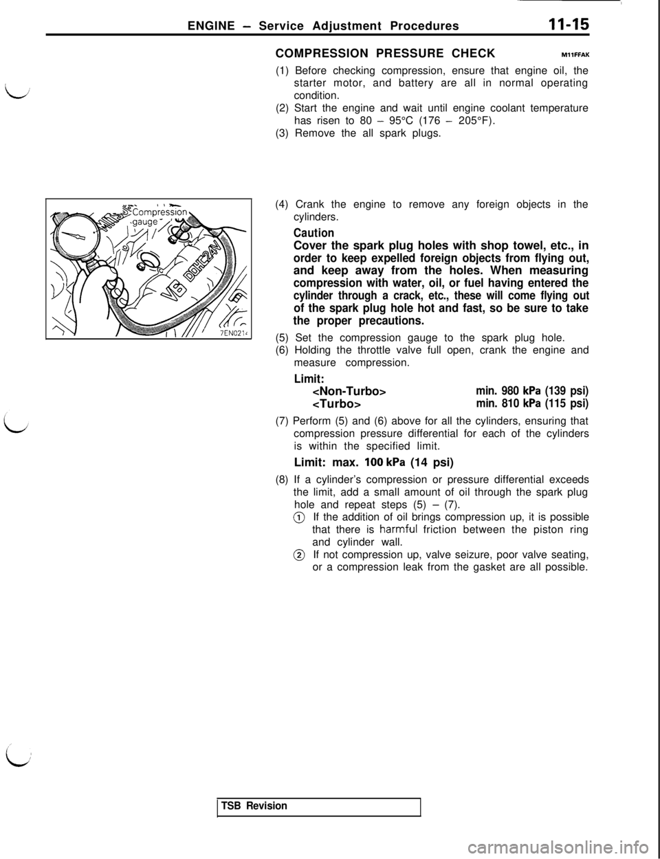
ENGINE - Service Adjustment Procedures11-15COMPRESSION PRESSURE CHECKMllFFAK
(1) Before checking compression, ensure that engine oil, the
starter motor, and battery are all in normal operating
condition.
(2) Start the engine and wait until engine coolant temperature
has risen to 80
- 95°C (176 - 205°F).
(3) Remove the all spark plugs.
(4) Crank the engine to remove any foreign objects in the
cylinders.
CautionCover the spark plug holes with shop towel, etc., in
order to keep expelled foreign objects from flying out,and keep away from the holes. When measuring
compression with water, oil, or fuel having entered the
cylinder through a crack, etc., these will come flying out
of the spark plug hole hot and fast, so be sure to take
the proper precautions.(5) Set the compression gauge to the spark plug hole.
(6) Holding the throttle valve full open, crank the engine and
measure compression.
Limit:
min. 980 kPa (139 psi)
min. 810 kPa (115 psi)(7) Perform (5) and (6) above for all the cylinders, ensuring that
compression pressure differential for each of the cylinders
is within the specified limit.
Limit: max.
100 kPa (14 psi)
(8) If a cylinder’s compression or pressure differential exceeds
the limit, add a small amount of oil through the spark plug
hole and repeat steps (5)
- (7).@If the addition of oil brings compression up, it is possible
that there is
harmf,uI friction between the piston ring
and cylinder wall.@If not compression up, valve seizure, poor valve seating,
or a compression leak from the gasket are all possible.
TSB Revision
Page 66 of 1146
11-16ENGINE - Service Adjustment Procedures
MANIFOLD VACUUM INSPECTION
MllFNAR
(1) The vehicle should be repaired as follows before the
inspection.
lEngine coolant temperature: 80 - 95°C (176 - 205°F)‘dl Lights, electric cooling fan, and accessories: OFF
l Transaxle: Neutral
(P for A/T)l Steering wheel: neutral position
(2) Connect a tachometer. (Refer to P.l l-l 3.)
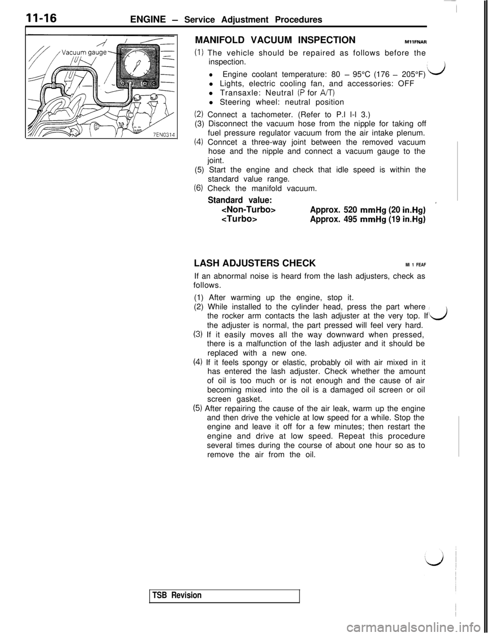
(3) Disconnect the vacuum hose from the nipple for taking off
fuel pressure regulator vacuum from the air intake plenum.
(4) Conncet a three-way joint between the removed vacuum
hose and the nipple and connect a vacuum gauge to the
joint.
(5) Start the engine and check that idle speed is within the
standard value range.
(6) Check the manifold vacuum.
Standard value:
*
Approx. 495 mmHg (19 in.Hg)LASH ADJUSTERS CHECK
Ml 1 FEAFIf an abnormal noise is heard from the lash adjusters, check as
follows.
(1) After warming up the engine, stop it.
(2) While installed to the cylinder head, press the part where
the rocker arm contacts the lash adjuster at the very top. If
the adjuster is normal, the part pressed will feel very hard.
d
(3) If it easily moves all the way downward when pressed,
there is a malfunction of the lash adjuster and it should be
replaced with a new one.
(4) If it feels spongy or elastic, probably oil with air mixed in it
has entered the lash adjuster. Check whether the amount
of oil is too much or is not enough and the cause of air
becoming mixed into the oil is a damaged oil screen or oil
screen gasket.
(5) After repairing the cause of the air leak, warm up the engine
and then drive the vehicle at low speed for a while. Stop the
engine and leave it off for a few minutes; then restart the
engine and drive at low speed. Repeat this procedure
several times during the course of about one hour so as to
remove the air from the oil.
TSB Revision
Page 68 of 1146
II-18ENGINE - Engine Assembly
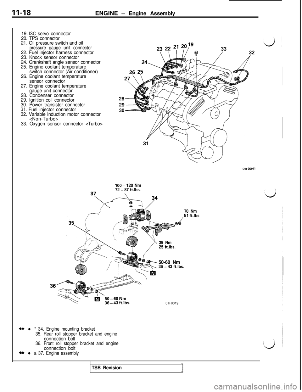
19. ISC servo connector
20. TPS connector
21. Oil pressure switch and oil
pressure gauge unit connector22. Fuel injector harness connector
23. Knock sensor connector
24. Crankshaft angle sensor connector
25. Engine coolant temperature
switch connector (Air conditioner)
26. Engine coolant temperature
sensor connector
27. Engine coolant temperature
gauge unit connector
28. Condenser connector
29. Ignition coil connector
30. Power transistor connector
31. Fuel injector connector
32. Variable induction motor connector
33. Oxygen sensor connector
2930lOO-
120 Nm72 - 87 ft.lbs.
70 Nm
,51 ftlbs
** l * 34. Engine mounting bracket
35. Rear roll stopper bracket and engine
connection bolt36. Front roll stopper bracket and engineconnection bolt** l a 37. Engine assembly35 Nm
25 ft.lbs.
?I,---R
50-60 Nm36 - 43 ftlbs.
OlFOO19
TSB Revision
Page 73 of 1146
ENGINE - Winder Head Gasket11-23
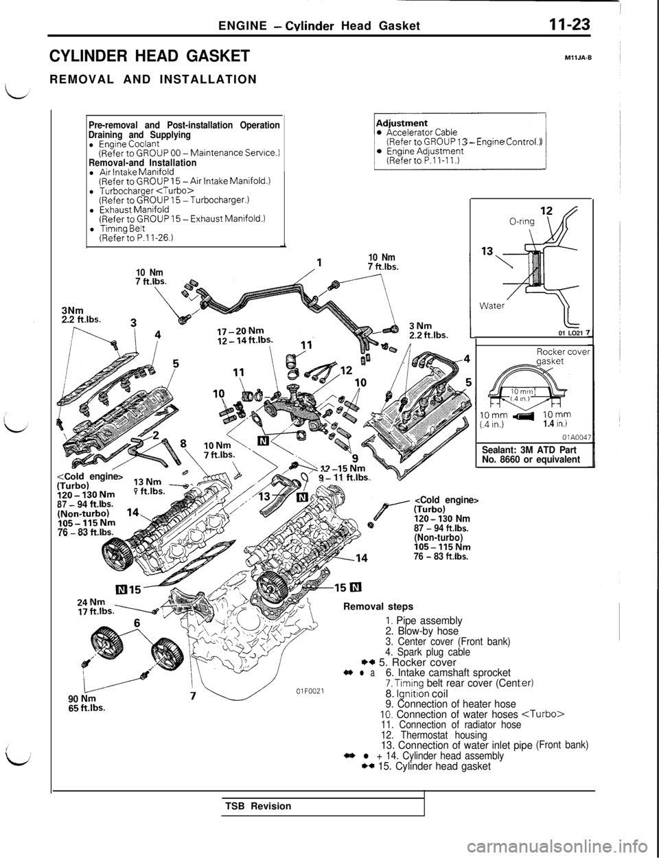
CYLINDER HEAD GASKETREMOVAL AND INSTALLATION
MllJA-6
Pre-removal and Post-installation Operation
Draining and Supplying
l Engine Coolant(Refer to GROUP 00 -Maintenance Service.)Removal-and Installationl Air Intake Manifold(Refer to GROUP 15 -Air intake Manifold.)l Turbocharger
10 Nm3Nm
2.2 klbs.P
~~(Refer to GROUP 13 - Engrne Control.)
10 Nm7 ft.lbs.
7 ft.lbs.\
120-nng
‘3, ;
%
;;
Water01 LO21
7
i2o-IjONmY rt.lDS.
87
- 94 ft.lbs.
76 - 83 ft.lbs.d
I. Pipe assembly
2. Blow-by hose
90
Nm3. Center cover (Front bank)
4. Spark plug cable
HI 5. Rocker cover4* l a
I
6. Intake camshaft sprocket7. Timing belt rear cover (Cent
7.----A//OlFOO218. Ignition coil9. Connection of heater hose10. Connection of water hoses
Rocker coverIOmm
410mm(.4 in.)1.4 in.)
OlA004;
Sealant: 3M ATD Part
No. 8660 or equivalent
.er)
tl-urbo>11. Connection of radiator hose
12. Thermostat housing
13. Connection of water inlet pipe** l + 14. Cylinder head assembly** 15. Cylinder head gasket
(Front bank)TSB Revision
Page 74 of 1146
11-24ENGINE - Cylinder Head Gasket
ldentlfrcatlonmark
01 N009iOlL0472
0111044
JI
j:: 1: :: ::p:i
c1
Q80401Q5 c
Frontbank074930296
- OlL105j8
TSB Revision
5SERVICE POINTS OF REMOVALMllJBBF
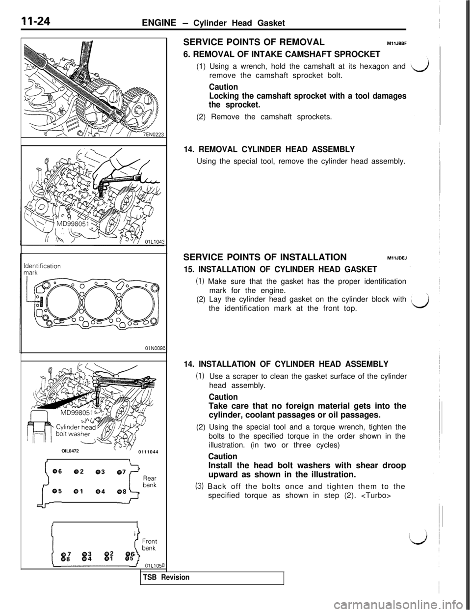
6. REMOVAL OF INTAKE CAMSHAFT SPROCKET
(1) Using a wrench, hold the camshaft at its hexagon and
remove the camshaft sprocket bolt.
Caution
Locking the camshaft sprocket with a tool damages
the sprocket.(2) Remove the camshaft sprockets.
14. REMOVAL CYLINDER HEAD ASSEMBLYUsing the special tool, remove the cylinder head assembly.
SERVICE POINTS OF INSTALLATION
MllJDEJ
15. INSTALLATION OF CYLINDER HEAD GASKET
(1) Make sure that the gasket has the proper identification
mark for the engine.
(2) Lay the cylinder head gasket on the cylinder block with
the identification mark at the front top.
14. INSTALLATION OF CYLINDER HEAD ASSEMBLY
(1)Use a scraper to clean the gasket surface of the cylinder
head assembly.
CautionTake care that no foreign material gets into the
cylinder, coolant passages or oil passages.
(2) Using the special tool and a torque wrench, tighten the
bolts to the specified torque in the order shown in the
illustration. (in two or three cycles)
CautionInstall the head bolt washers with shear droop
upward as shown in the illustration.
(3) Back off the bolts once and tighten them to the
specified torque as shown in step (2).
Page 108 of 1146
13-2
Boost Meter
Components Location........................................................36
Crank Angle Sensor
............................................................72Detonation Sensor................................................................84EGR Control Solenoid Valve
EGR Temperature Sensor
Fuel Pump Operation Check................................................137Fuel Pump Relay No. 2........................................................53Fuel Pump Resistor............................................................53
Idle Position Switch............................................................68Idle Speed Control Servo (Stepper Motor Type)............1 IOIgnition Coil and Power Transistor....................................115Ignition Switch-ST and Inhibitor Switch ................76Ignition Switch-ST
Injectors
94
Oxygen Sensor
Power Steering Oil Pressure Switch................................80Power Supply and Ignition Switch-IG................................41
Purge Control Solenord Valve............................................1 19Release of Residual Pressure from High
Pressure Fuel Hose............................................................137Throttle Position Sensor....................................................65Top Dead Center Sensor....................................................70Variable Induction Control Servo (DC Motor)
SERVICE ADJUSTMENT PROCEDURES............................31
Adjustment of Fixed SAS....................................................35Adjustment of Idle Position Switch and
Throttle Position Sensor (TPS)............................................33Basic Idle Speed Adjustment............................................31Throttle Body (Throttle Valve Area) Cleaning....................33
SPECIAL TOOLS........................................................................8
SPECIFICATIONS
....................................................................6
General Specifications........................................................6Sealant....................................................................................7Service Specifications........................................................7
THROlTLE BODY....................................................................143
TROUBLESHOOTING............................................................9
Check Chart Classified by Problem Symptoms................16Circuit Diagram....................................................................18Engine Warning Light (Malfunction Indicator Light)........11Explanation and Cautions about Harness Check............10Explanation of Troubleshooting Procedures....................9Fuel Tank and Fuel Line........................................................30
Problem Symptoms Table (For Your Information)............17Self-diagnosis........................................................................12)
I
Page 112 of 1146
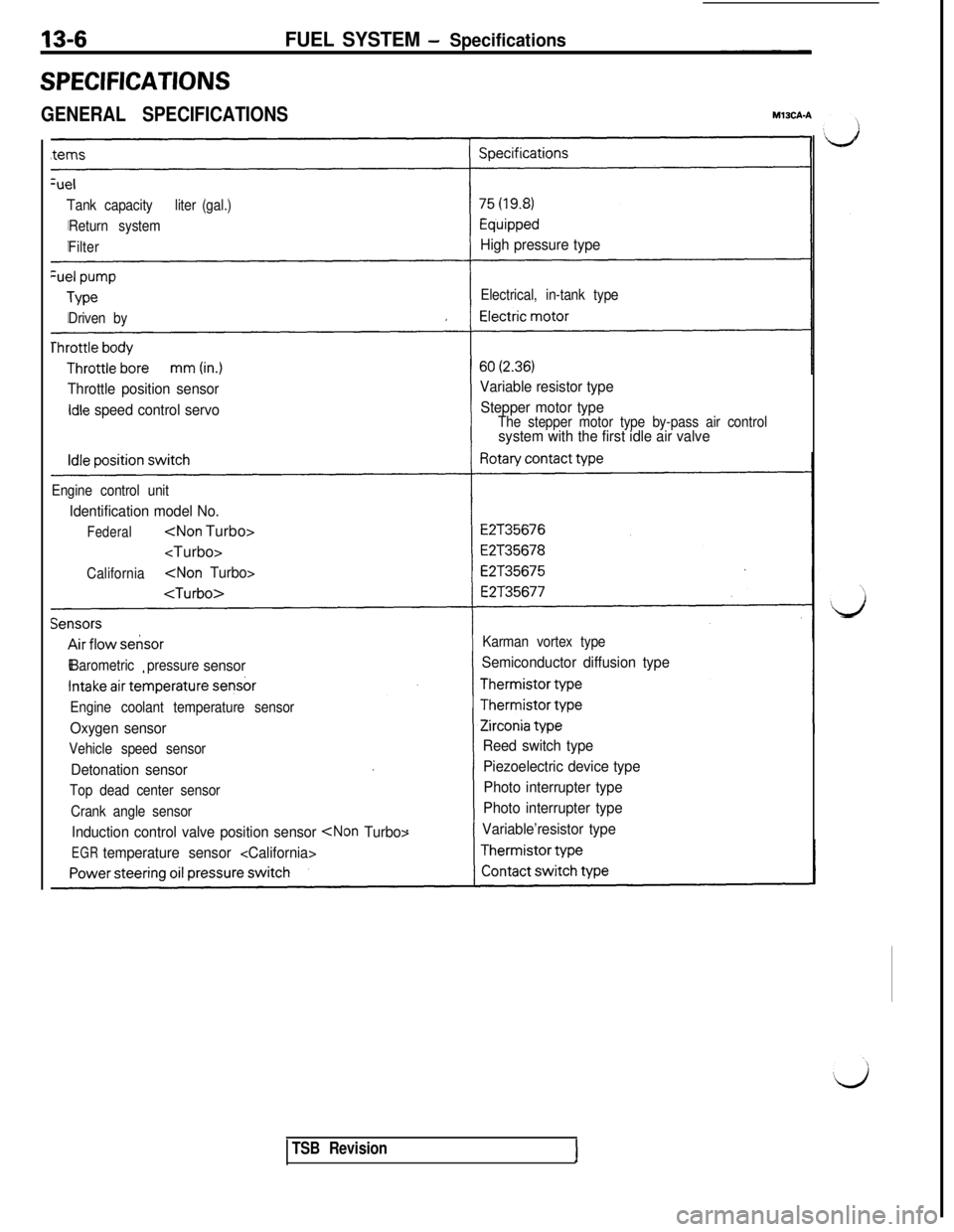
Tank capacityliter (gal.)
Return system
Filter
High pressure type
Electrical, in-tank type
Driven by
Throttle position sensor
idle speed control servoVariable resistor type
Stepper motor typeThe stepper motor type by-pass air controlsystem with the first idle air valve
Engine control unit
Identification model No.
Federal
California
Karman vortex type
Barometric pressure
sensorSemiconductor diffusion type
Engine coolant temperature sensor
Oxygen sensor
Vehicle speed sensor
Detonation sensor
Top dead center sensor
Crank angle sensor
Induction control valve position sensor
EGRtemperature sensor
Piezoelectric device type
Photo interrupter type
Photo interrupter type
Variable’resistor type
13-6FUEL SYSTEM - Specifications
SPECIFICATIONS
GENERAL SPECIFICATIONS
TSB Revision
Page 113 of 1146
FUEL SYSTEM - SDecifications
L
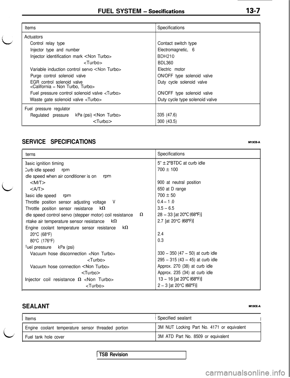
Items
Actuators
Control relay type
Injector type and number
Injector identification mark
Variable induction control servo
Purge control solenoid valve
EGR control solenoid valve
Fuel pressure control solenoid valve
Waste gate solenoid valve
Fuel pressure regulator
Regulated pressure
kPa (psi)
Specifications
Contact switch type
Electromagnetic, 6
BDH210
BDL360
Electric motor
ON/OFF type solenoid valve
Duty cycle solenoid valve
ON/OFF type solenoid valve
Duty cycle type solenoid valve
335 (47.6)
300 (43.5)
SERVICE SPECIFICATIONS
i
ternsSpecifications
3asic ignition timing5” -t 2”BTDC at curb idle
3urb idle speedrpm700 * 100
dle speed when air conditioner is on
rpm
3asic idle speedrpm700 + 50
Throttle position sensor adjusting voltageV0.4- 1 .o
Throttle position sensor resistancek03.5 - 6.5
dle speed control servo (stepper motor) coil resistance028 - 33 [at 20°C (68”F)I
ntake air temperature sensor resistancekfi2.7 [at 20°C (68”F)I
Engine coolant temperature sensor resistancekQ
20°C (68°F)
2.4
80°C (176°F)0.3
%el pressurekPa (psi)
Vacuum hose disconnection
295 - 315 (43 - 45) at curb idle
Vacuum hose connection
Sz
2 - 3 [at 20°C (68”F)I
SEALANTMlXE-A
IItems1 Specified sealantI
/
L
Engine coolant temperature sensor threaded portion3M NUT Locking Part No. 4171 or equivalent
Fuel tank hole cover3M ATD Part No. 8509 or equivalent
1 TSB Revision
Page 117 of 1146
FUEL SYSTEM - Troubleshooting13-11
L
L
Sensor side6FU1215
Malfunctionl
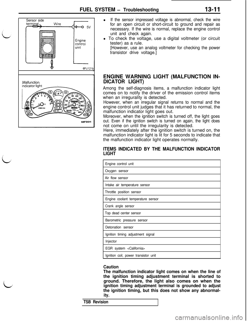
If the sensor impressed voltage is abnormal, check the wire
for an open circuit or short-circuit to ground and repair as
necessary. If the wire is normal, replace the engine control
unit and check again.l To check the voltage, use a digital voltmeter (or circuit
tester) as a rule.
[However, use an analog voltmeter for checking the power
transistor drive voltage.]ENGINE WARNING LIGHT (MALFUNCTION IN-
DICATOR LIGHT)
Among the self-diagnosis items, a malfunction indicator lightcomes on to notify the driver of the emission control items
when an irregurality is detected.
However, when an irregular signal returns to normal and theengine control unit judges that it has returned to normal, the
malfunction indicator light goes out.
Moreover, when the ignition switch is turned off, the light goes
out. Even if the ignition switch is turned on again, the light doesnot come on until the irregularity is detected.
Here, immediately after the ignition switch is turned on, the
malfunction indicator light is lit for 5 seconds to indicate that
the malfunction indicator light operates normally.
ITEMS INDICATED BY THE MALFUNCTION INDICATOR
LIGHT
Engine control unit
Oxygen sensor
Air flow sensor
Intake air temperature sensor
Throttle position sensor
Engine coolant temperature sensor
Crank angle sensor
Top dead center sensor
Barometric pressure sensor
Detonation sensor
Ignition timing adjustment signal
Injector
EGR system
Ignition coil, power transistor unit
Caution
The malfunction indicator light comes on when the line ofthe ignition timing adjustment terminal is shorted to
ground. Therefore, the light also comes on when the
ignition timing adjustment terminal is grounded to adjust
the ignition timing, but this does not show any abnormal-
ity.
TSB Revision
Page 119 of 1146
FUEL SYSTEM - Troubleshootinn
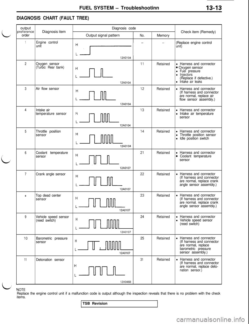
DIAGNOSISCHART (FAULT TREE)
i
L
Foutput
Diagnosis codeIreferenceDiagnosis item
Check item (Remedy)orderOutput signal patternNo.Memory
1Engine controlunit
:r- -
(Replace engine controlunit)
12A0104
2Oxygen sensorRetainedl Harness and connector(Turbo: Rear bank)
Cnn I’
0 Oxygen sensorl Fuel pressurel Injectors(Replace if defective.)
12A0104l Intake air leaks
3Air flow sensor
:n ‘*
Retainedl Harness and connector
(If harness and connector
are normal, replace air
flow sensor assembly.)
12A0104
4Intake airRetainedl Harness and connector
temperature sensorH
Ln I3
l Intake air temperature
sensor
12A0104
5Throttle position
sensor
:n I4
Retainedl Harness and connectorl Throttle position sensorl Idle position switch
12AO104
6Coolant temperature
:nn 21
Retainedl Harness and connector
sensor0 Coolant temperature
sensor12A0107
7Crank angle sensor
:nn 22
Retainedl Harness and connector
(If harness and connector
are normal, replace crank
angle sensor assembly.)
12A01078
Top dead centerRetainedl Harness and connector
sensor
:nn 23
(If harness and connector
are normal. replace crank
angle sensor assembly.)
12A0107
9Vehicle speed sensor24Retainedl Harness and connector
(reed switch)H
UInnnn
l Vehicle speed sensor
(reed switch)
L12A0107
10Barometric pressure25Retainedl Harness and connector
sensorHu I
nnluln
(If harness and connector
are normal, replace
Lbarometric pressure
12A0107sensor assembly.)
11Detonation sensor31Retainedl Harness and connector
:-r-uuuL
(If harness and connector
are normal, replace deto-
nation sensor.)
L-NOTE
12A0468
Replace the engine control unit if a malfunction code is output although the inspection reveals that there is no problem with the check
items.TSB Revision