relay MITSUBISHI 3000GT 1991 User Guide
[x] Cancel search | Manufacturer: MITSUBISHI, Model Year: 1991, Model line: 3000GT, Model: MITSUBISHI 3000GT 1991Pages: 1146, PDF Size: 76.68 MB
Page 132 of 1146
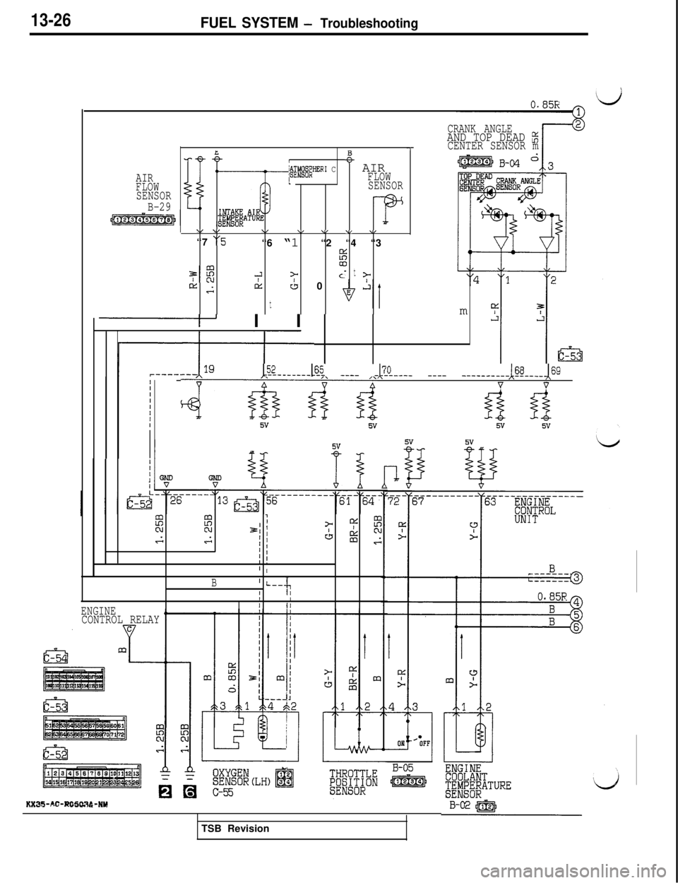
13-26FUEL SYSTEM - Troubleshooting
AIR
FLOW
SENSOR
B-29
LB-eI~@.@JER’ C+- AIRIFLOW
SENSOR
\/ v\/\/ \/ \I \,“7
“5“6 “1 “2 “4 “3
%
7:
00-3>t
Ac- z-rtis
t
CL 0
I I I
iIIIIIIII
III1I
~ZL---&i ____ -&L--- ____ --------&----&9
4&&d vv
CRANK ANGLEAND TOP DEAD z-7CENTER SENSOR mm
2E?7IN21 )= 4:EGGI ’CL g
) 1G
I !’ I
B’ L--l‘;rII
ENGINEIII
CONTROL RELAY
5vii
KX35-AC-RO5tX36-NYTSB Revision
Page 133 of 1146
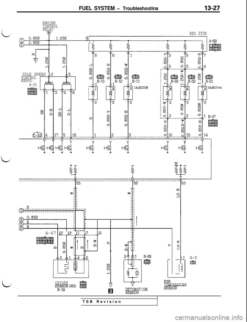
FUEL SYSTEM - Troubleshootina
ENGINECONTROLRELAY
RES
Q0.65R1.25R4,1n RKD1I T1
STOR
e.&I
IDLE SPEED /\2CONTROL,.
SERVO
B-35
YY Y YY Y
TOR
mI
III4IIIIIIIL---wI IA-67 ,,2-,,8--,,1-,,?_--,,lOI II I
r----1I II I5
c;IImn‘3
A-Z
&I
-
:1lI-II
OXYGENS;K;R(RH)TEMPERATURETSB Revision
Page 134 of 1146
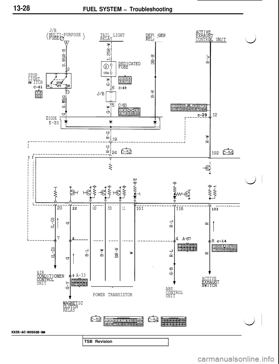
13-28FUEL SYSTEM - Troubleshooting
J/B
(MULTI-PURPOSEFUSE@>TAIL LIGHTRELAYDEF(RELfjGERKixCONTR
m
ONC-69'(3I
if2-
L&ia3
dd
I0_-w1DIODE II
3
d
STOP
LIGHT
SW ITCHC-6112
El34c-29
1r--------'
fII
--__---_-__------___------~~--- \1,--Iy----------------------------Jd
71
z?124 t&r-----------------------------7;I IIV
I---
w
Sk
w,t
>
JI
v
----_10
.----
5
cb-----
3
-.---
!xI
%
:------_22
6-------
J
1
&I
8 A-33
11
.----
3
- -----------
r
103
c
I
128 c-14
pER!Eq?
v
.-----_-_-----_
AIR
E;;F#ONER
UNITACTIVEisiii%!iTc
ABS
CONTROLUNIT
Y
POWER TRANSISTOR
FlffiWRELAYKX35-AC-R0503B-NY
TSB Revision
I
Page 135 of 1146
![MITSUBISHI 3000GT 1991 User Guide FUEL SYSTEM - Troubleshooting13-29
ENGINE
CONTROL
RELAYF
1 7=2
c----IIIIIIII2,(2Io FUEL
) SE
PRESSURE
SOLENOID
VALVE
IfII
I
I
I
I
J
]i#&B,D i
A-20
1
WASTE
GATE
SOLENOIDVALVE
/
7 EGRi ~XE~~OID
I
; A-21 MITSUBISHI 3000GT 1991 User Guide FUEL SYSTEM - Troubleshooting13-29
ENGINE
CONTROL
RELAYF
1 7=2
c----IIIIIIII2,(2Io FUEL
) SE
PRESSURE
SOLENOID
VALVE
IfII
I
I
I
I
J
]i#&B,D i
A-20
1
WASTE
GATE
SOLENOIDVALVE
/
7 EGRi ~XE~~OID
I
; A-21](/img/19/57085/w960_57085-134.png)
FUEL SYSTEM - Troubleshooting13-29
ENGINE
CONTROL
RELAYF
1 7=2
c----IIIIIIII2,(2Io FUEL
) SE
PRESSURE
SOLENOID
VALVE
IfII
I
I
I
I
J
]i#&B,D i
A-20
1
WASTE
GATE
SOLENOIDVALVE
/
7 EGRi ~XE~~OID
I
; A-21
L
1 A-70
j A-72
f ENGINEj jXICI$ROL
I
-------13s
3.------
s
10
/\1
>
J
c
”-_-
1 A-18
3P
~;~E&DIAGNOSIS #Fjhl;;ON
CONNECTORADJUSTMENT
EFfq&@gCONNECTOR
d
Efpggggg]
I B-OS
ENGINE
COOLANT
Q&;EEATURE ,,'I/\FOR AIR)/@ICONDITIONEROFF --xOlJ
POWER STEERING;tK;BESSURETSB Revision
Page 147 of 1146
FUEL SYSTEM - On-vehicle Inspection of MPI Components13-41
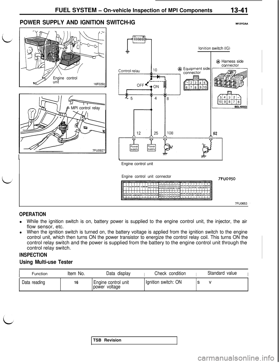
POWER SUPPLY AND IGNITION SWITCH-IG
Engine control
unit
16FO29:
Q-i=++=
iA MPI control relay
ml3Yuu
lcmition switch (IG)
@ Harness sideccmnector
62
I
Engine control unit
Engine control unit connector7FUO950
OPERATIONl
While the ignition switch is on, battery power is supplied to the engine control unit, the injector, the airflow sensor, etc.
lWhen the ignition switch is turned on, the battery voltage is applied from the ignition switch to the engine
control unit, which then turns ON the power transistor to energize the control relay coil. This turns ON thecontrol relay switch and the power is supplied from the battery to the engine control unit through the
control relay switch.
INSPECTION
Using Multi-use Tester
IFunctionItem No.Data displayICheck conditionIStandard valueI
Data reading16Engine control unit
power voltageIgnition switch: ONsv
TSB Revision
Page 148 of 1146
IS-42FUEL SYSTEM - On-vehicle Inspection of MPI Components
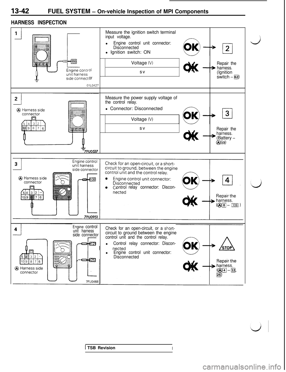
HARNESS INSPECTION
Measure the ignition switch terminalinput voltage.l
Engine control unit connector:
Disconnectedl Ignition switch: ON
01
orOlLO427Voltage
(V)svRepair the
harness.
(Ignitionswitch -@I
Measure the power supply voltage ofthe control relay.l Connector: Disconnected
Voltage
(V)sv
Repair the
harness.
(Battery -
@IIN
ontrolrelay connector: Discon-
Engine controlunit harnessCheck for an open-circuit, or a short-
side connectorcircuit to ground between the enginecontrol unit and the control relay.l
Control relay connector: Discon-l
Engine control unit connector:
Disconnected
1 TSB RevisionI
Page 149 of 1146
FUEL SYSTEM - On-vehicle Inspection of MPI Components13-43OlLO521
01 LO220
011022:
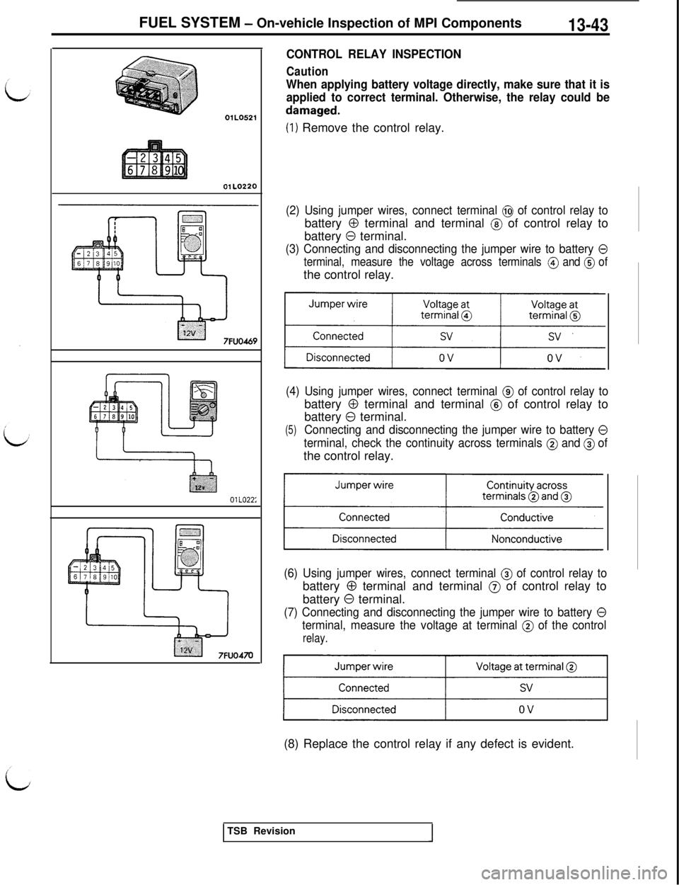
CONTROL RELAY INSPECTION
Caution
When applying battery voltage directly, make sure that it is
applied to correct terminal. Otherwise, the relay could be
damaged.
(1) Remove the control relay.
(2) Using jumper wires, connect terminal @ of control relay tobattery
0 terminal and terminal @ of control relay to
battery
0 terminal.
(3) Connecting and disconnecting the jumper wire to battery 0
terminal, measure the voltage across terminals @ and @ ofthe control relay.
(4) Using jumper wires, connect terminal @ of control relay tobattery
0 terminal and terminal @ of control relay to
battery
0 terminal.
(5)Connecting and disconnecting the jumper wire to battery 0
terminal, check the continuity across terminals @ and @ ofthe control relay.
(6) Using jumper wires, connect terminal @ of control relay tobattery
0 terminal and terminal @ of control relay to
battery
0 terminal.
(7) Connecting and disconnecting the jumper wire to battery 0
terminal, measure the voltage at terminal @ of the control
relay.(8) Replace the control relay if any defect is evident.
TSB Revision
Page 151 of 1146
FUEL SYSTEM -On-vehicle Inspection of MPI Components13-45
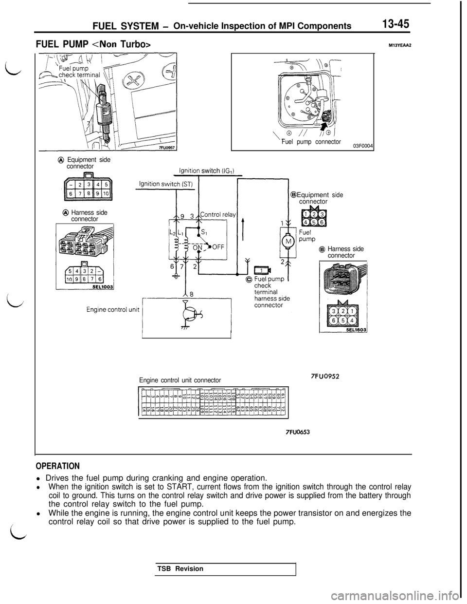
FUEL PUMP
@ Equipment side
connector
@ Harness side
connector
lqnition switch (IG,i
LL--- /A&
\“// //@JFuel pump connector
Engine control unit connectorEquipment
connectorside
@ Harness side
connector
7FUO653
7FUO952
M13YEAA2
OPERATIONl Drives the fuel pump during cranking and engine operation.
lWhen the ignition switch is set to START, current flows from the ignition switch through the control relay
coil to ground. This turns on the control relay switch and drive power is supplied from the battery throughthe control relay switch to the fuel pump.
lWhile the engine is running, the engine control unit keeps the power transistor on and energizes the
icontrol relay coil so that drive power is supplied to the fuel pump.
LTSB Revision
Page 153 of 1146
FUEL SYSTEM - On-vehicle inspection of MPI Components
@ Harness side
connector6
1
@ Harness side
connector
77FUO475
-
Engine controlunit harnessside connector
Q Harness side
-1
=7FUO476
9 Harnessside
connec-
tor
@ Harness side connector
7FUO956
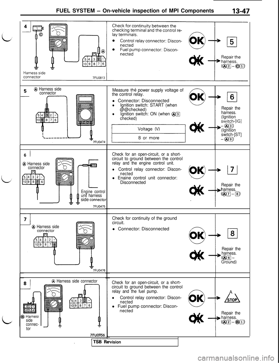
Measure th& power supply voltage of
the control relay.l Connector: Disconnected
OK
lIgnition switch: START (when0
@@checked)lIgnition switch: ON (when @@
checked)
cl6
t
Repair the
harness.
(Ignition
switch-[IGI
- @El)
(Ignition
switch-[ST]
- @El)
Check for an open-circuit, or a short-
circuit to ground between the controlrelay and the engine control unit.
lControl relay connector: Discon-nectedl Enaine control unit connector:
Disconnected
Repair the
harness.
@El-lg
Check for continuity of the ground
circuit.l Connector: Disconnected
Repair the
harness.
L%n~)
Check for an open-circuit, or a short-circuit to ground between the controlrelay and the fuel pump.A
lControl relay connector: Discon-nected(OK)+ Adl Fuel pump connector:
Discon-netted
Repair the
harness.
@I@-@g)
I
vision
Page 154 of 1146
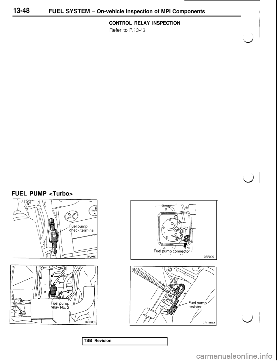
13-48FUEL SYSTEM - On-vehicle Inspection of MPI Components
CONTROL RELAY INSPECTIONRefer to
P.13-43.FUEL PUMP
\/I ,,03FOOO
TSB Revision