ECU MITSUBISHI 3000GT 1991 Owner's Guide
[x] Cancel search | Manufacturer: MITSUBISHI, Model Year: 1991, Model line: 3000GT, Model: MITSUBISHI 3000GT 1991Pages: 1146, PDF Size: 76.68 MB
Page 304 of 1146
14-10COOLING - Radiator
r-----I
113
EY
4 :
2 :
i.-.-..i
0312161908
Ionnector04FOOO8
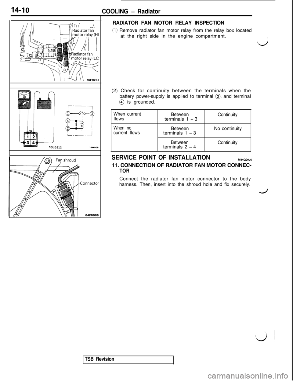
RADIATOR FAN MOTOR RELAY INSPECTION
(1) Remove radiator fan motor relay from the relay box located
at the right side in the engine compartment.
Ll(2) Check for continuity between the terminals when the
battery power-supply is applied to terminal
0, and terminal@ is grounded.
When current
flowsBetweenterminals 1
- 3Continuity
When nocurrent flowsBetweenterminals 1 - 3No continuity
Betweenterminals 2 - 4Continuity
SERVICE POINT OF INSTALLATIONM14QDAH
11. CONNECTION OF RADIATOR FAN MOTOR CONNEC-
TORConnect the radiator fan motor connector to the body
harness. Then, insert into the shroud hole and fix securely.
TSB Revision
Page 322 of 1146
15-12INTAKE AND EXHAUST - lntercooier
SERVICE POINT OF REMOVALMlSTSAC
13. REMOVAL OF ENGINE OIL COOLERIDisconnect the hose from the engine oil cooler and remove
the engine oil cooler only.
IL)
INSPECTIONMISTCAB
lCheck the intercooler fins for bending, damage, or foreign
matter.
lCheck the intercooler hoses for cracking, damage, or wear.
Air Intake hose B
Air hose
05FOO21
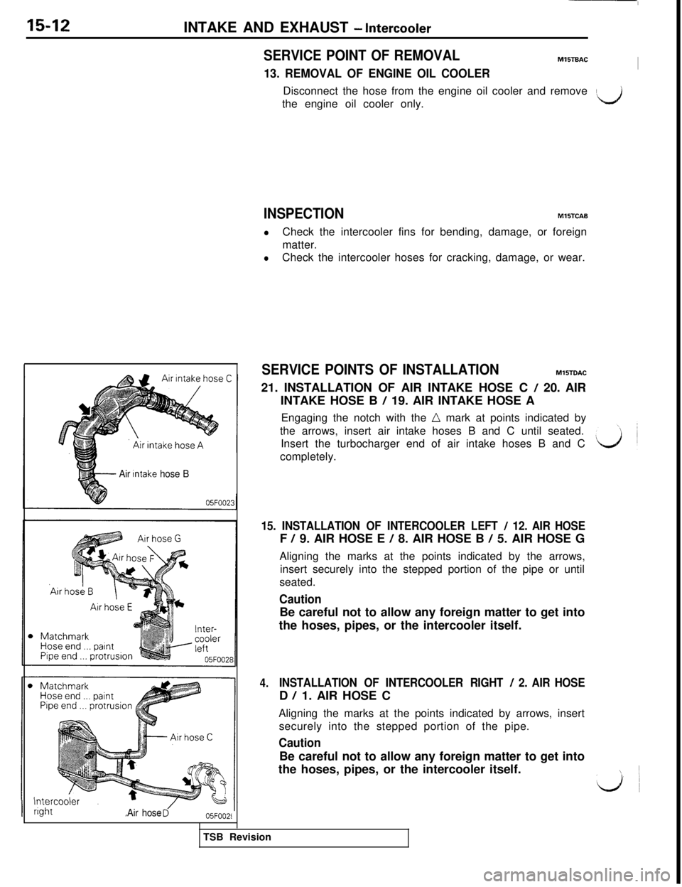
SERVICE POINTS OF INSTALLATIONMlSTDAC
21. INSTALLATION OF AIR INTAKE HOSE C
/ 20. AIR
INTAKE HOSE B
/ 19. AIR INTAKE HOSE A
Engaging the notch with the
n mark at points indicated by
the arrows, insert air intake hoses B and C until seated.
Insert the turbocharger end of air intake hoses B and C
completely.
15. INSTALLATION OF INTERCOOLER LEFT / 12. AIR HOSEF
/ 9. AIR HOSE E / 8. AIR HOSE B / 5. AIR HOSE G
Aligning the marks at the points indicated by the arrows,
insert securely into the stepped portion of the pipe or until
seated.
CautionBe careful not to allow any foreign matter to get into
the hoses, pipes, or the intercooler itself.
4.INSTALLATION OF INTERCOOLER RIGHT / 2. AIR HOSED
/ 1. AIR HOSE C
Aligning the marks at the points indicated by arrows, insert
securely into the stepped portion of the pipe.
CautionBe careful not to allow any foreign matter to get into
the hoses, pipes, or the intercooler itself.
1 ~
LJ~TSB Revision
Page 330 of 1146
15-20INTAKE AND EXHAUST - Turbocharger (Front)
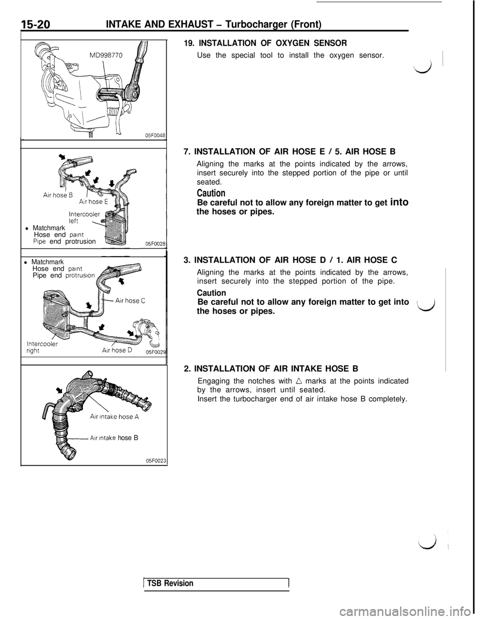
19. INSTALLATION OF OXYGEN SENSORUse the special tool to install the oxygen sensor.
I;,iI-
i=x---b05F004E
l MatchmarkHose end paintPipe end protrusion05F002F
l MatchmarkHose end paintPipe end protrusion
Intercoolerright
J
Air Intake hose B
05FOO237. INSTALLATION OF AIR HOSE E
/ 5. AIR HOSE B
Aligning the marks at the points indicated by the arrows,
insert securely into the stepped portion of the pipe or until
seated.
CautionBe careful not to allow any foreign matter to get into
the hoses or pipes.
3. INSTALLATION OF AIR HOSE D
/ 1. AIR HOSE C
Aligning the marks at the points indicated by the arrows,
insert securely into the stepped portion of the pipe.
CautionBe careful not to allow any foreign matter to get into
the hoses or pipes.
LJ2. INSTALLATION OF AIR INTAKE HOSE B
Engaging the notches with
LL marks at the points indicated
by the arrows, insert until seated.
Insert the turbocharger end of air intake hose B completely.
[ TSB RevisionI
Page 333 of 1146
INTAKE AND EXHAUST - Turbocharger (Rear)15-23
Air intake hose A
Air intake hose BHose end
paint
3
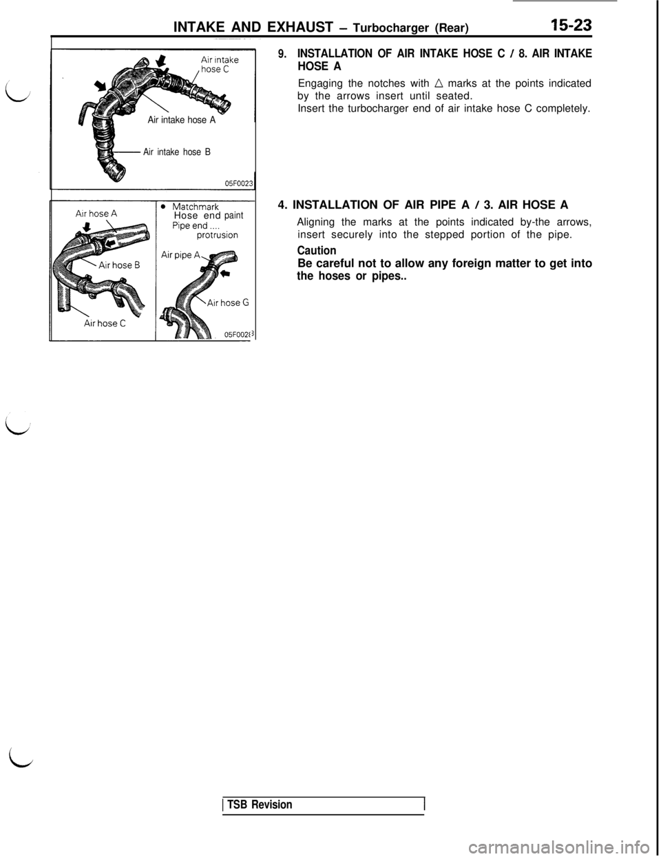
9.INSTALLATION OF AIR INTAKE HOSE C / 8. AIR INTAKE
HOSE AEngaging the notches with
n marks at the points indicated
by the arrows insert until seated.
Insert the turbocharger end of air intake hose C completely.
4. INSTALLATION OF AIR PIPE A
/ 3. AIR HOSE A
Aligning the marks at the points indicated by-the arrows,
insert securely into the stepped portion of the pipe.
CautionBe careful not to allow any foreign matter to get into
the hoses or pipes..
1 TSB Revision
id
Page 363 of 1146
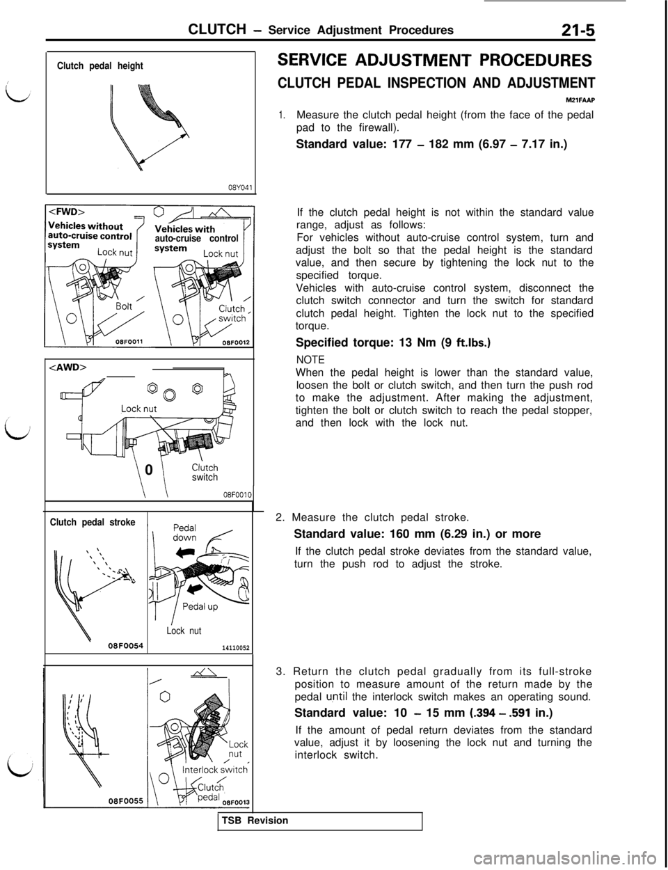
CLUTCH - Service Adjustment Procedures21-5
Clutch pedal height
08YO41
auto-cruise control
\ \ 0Cl;tchswitch
\ \08F0010
Clutch pedal stroke
Lock nut
08F005414110052
SERVICE ADJUSTMENT PROCEDURES
CLUTCH PEDAL INSPECTION AND ADJUSTMENTMZlFAAP
1.Measure the clutch pedal height (from the face of the pedal
pad to the firewall).
Standard value: 177
- 182 mm (6.97 - 7.17 in.)
If the clutch pedal height is not within the standard value
range, adjust as follows:
For vehicles without auto-cruise control system, turn and
adjust the bolt so that the pedal height is the standard
value, and then secure by tightening the lock nut to the
specified torque.
Vehicles with auto-cruise control system, disconnect the
clutch switch connector and turn the switch for standard
clutch pedal height. Tighten the lock nut to the specified
torque.
Specified torque: 13 Nm (9
ft.lbs.)
NOTEWhen the pedal height is lower than the standard value,
loosen the bolt or clutch switch, and then turn the push rod
to make the adjustment. After making the adjustment,
tighten the bolt or clutch switch to reach the pedal stopper,
and then lock with the lock nut.
2. Measure the clutch pedal stroke.
Standard value: 160 mm (6.29 in.) or more
If the clutch pedal stroke deviates from the standard value,
turn the push rod to adjust the stroke.
3. Return the clutch pedal gradually from its full-stroke
position to measure amount of the return made by the
pedal
u,ntil the interlock switch makes an operating sound.
Standard value: 10
- 15 mm (.394 - .591 in.)
If the amount of pedal return deviates from the standard
value, adjust it by loosening the lock nut and turning the
interlock switch.
TSB Revision
Page 370 of 1146
21-12CLUTCH - Clutch ControlOBFOOBf
!J
03FOOE
- Air intake hose B05FOO23
Air Intake
hose C
aAir intake hose A
Air hose CAir hose AI
05FOOZE
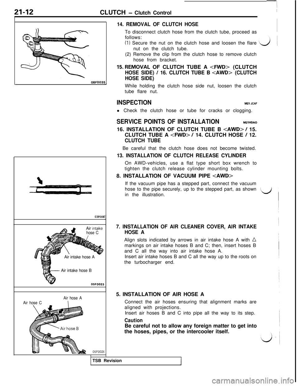
14. REMOVAL OF CLUTCH HOSETo disconnect clutch hose from the clutch tube, proceed as
follows:
(I) Secure the nut on the clutch hose and loosen the flare
nut on the clutch tube.
(2) Remove the clip from the clutch hose to remove clutch
hose from bracket.
15.REMOVAL OF CLUTCH TUBE A
HOSE SIDE) / 16. CLUTCH TUBE B
HOSE SIDE)While holding the clutch hose side nut, loosen the clutch
tube flare nut.
INSPECTIONM21 JCAFl Check the clutch hose or tube for cracks or clogging.
SERVICE POINTS OF INSTALLATIONM2lHDAO
16. INSTALLATION OF CLUTCH TUBE B
CLUTCH TUBE A
CLUTCH TUBEBe careful that the clutch hose does not become twisted.
13. INSTALLATION OF CLUTCH RELEASE CYLINDEROn AWD-vehicles, use a flat type short box wrench to
tighten the clutch release cylinder mounting bolts.
8. INSTALLATION OF VACUUM PIPE
hose to the pipe securely, up to the stepped part, as shown
in the illustration.
7. INSTALLATION OF AIR CLEANER COVER, AIR INTAKE
HOSE AAlign slots indicated by arrows in air intake hose A with
nmarkings on air intake hoses B and C; then, insert hoses B
and C all the way into air intake hose A.
Insert air intake hoses B and C all the way up to the roots on
the turbocharger end.
5. INSTALLATION OF AIR HOSE A
Connect the air hoses ensuring that alignment marks are
aligned with projections.
Insert air hoses B and C into pipe all the way to its step.
CautionBe careful not to allow any foreign matter to get into
the hoses, pipes, or the intercooler itself.
TSB Revision
Page 389 of 1146
MANUAL TRANSAXLE
110*u011009FO12
SERVICE ADJUSTMENT PROCEDURES
MZZFBAEl
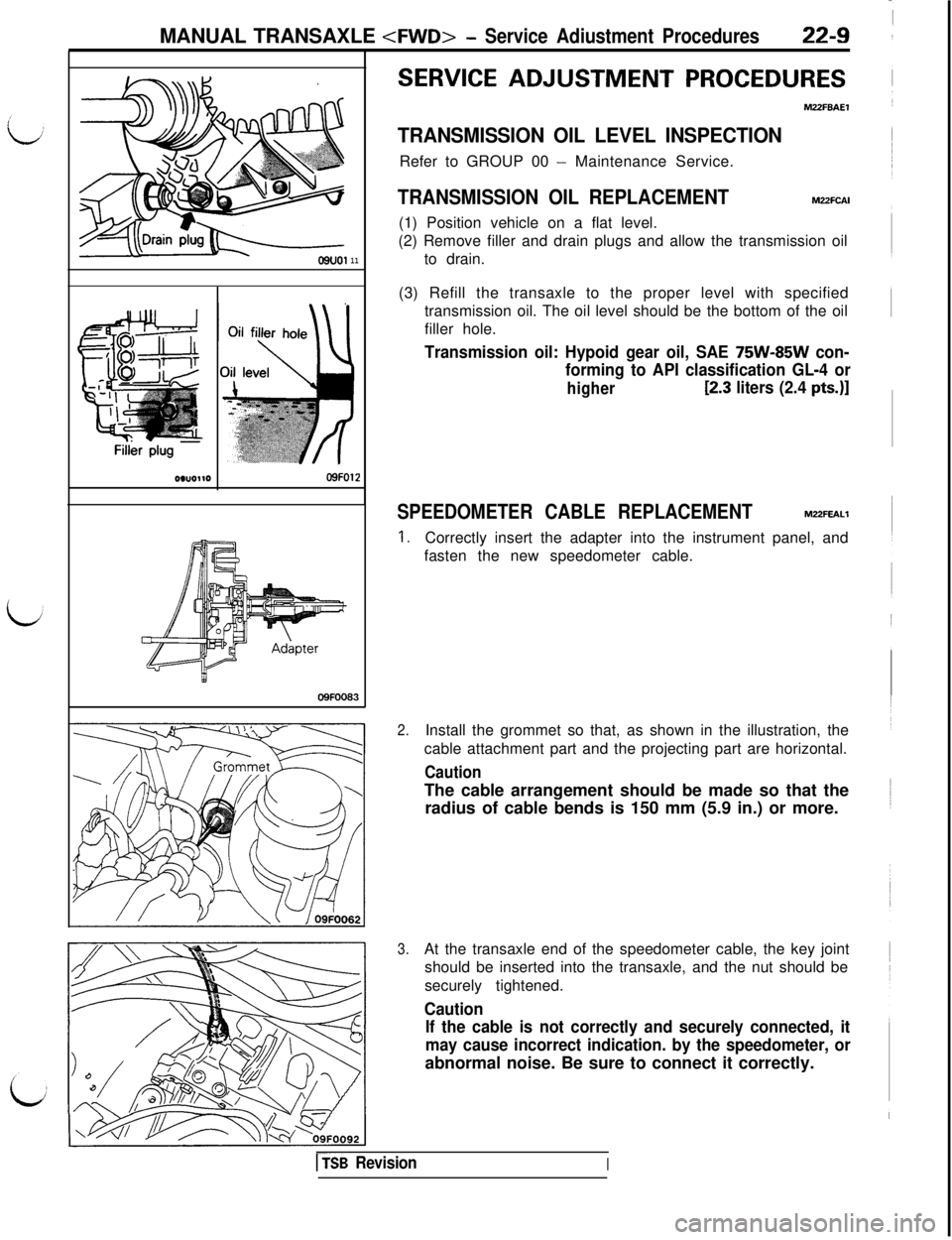
TRANSMISSION OIL LEVEL INSPECTIONRefer to GROUP 00
- Maintenance Service.
TRANSMISSION OIL REPLACEMENTM22FCAI(1) Position vehicle on a flat level.
(2) Remove filler and drain plugs and allow the transmission oil
to drain.
(3) Refill the transaxle to the proper level with specified
transmission oil. The oil level should be the bottom of the oil
filler hole.
Transmission oil: Hypoid gear oil, SAE 75W-85W con-
forming to API classification GL-4 or
higherC2.3 liters (2.4 pts.)]
SPEEDOMETER CABLE REPLACEMENTMUFEALl
1.Correctly insert the adapter into the instrument panel, and
fasten the new speedometer cable.
2.Install the grommet so that, as shown in the illustration, the
cable attachment part and the projecting part are horizontal.
CautionThe cable arrangement should be made so that the
radius of cable bends is 150 mm (5.9 in.) or more.
3.At the transaxle end of the speedometer cable, the key joint
should be inserted into the transaxle, and the nut should be
securely tightened.
Caution
If the cable is not correctly and securely connected, it
may cause incorrect indication. by the speedometer, orabnormal noise. Be sure to connect it correctly.
DSB RevisionI
Page 395 of 1146
MANUAL TRANSAXLE
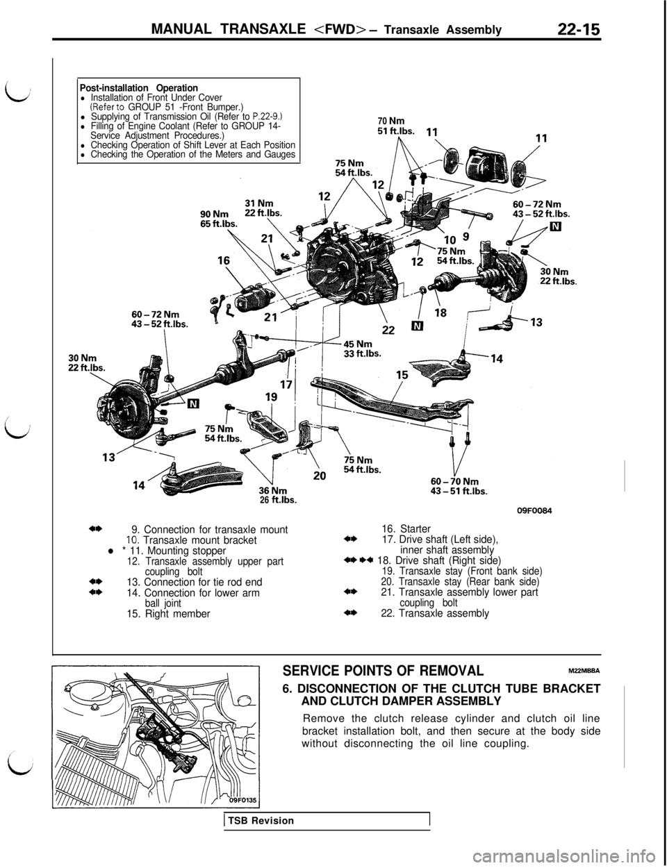
idPost-installation Operationl Installation of Front Under Cover(Referto GROUP 51 -Front Bumper.)l Supplying of Transmission Oil (Refer to P.22-9.)l Filling of Engine Coolant (Refer to GROUP 14-
Service Adjustment Procedures.)70 Nm
l Checking Operation of Shift Lever at Each Positionl Checking the Operation of the Meters and Gauges26
ft.lbs.09FOO84
4*9. Connection for transaxle mount16. Starter10. Transaxle mount bracket4*17. Drive shaft (Left side),
l * 11. Mounting stopperinner shaft assembly12. Transaxle assembly upper part+* ** 18. Drive shaft (Right side)
coupling bolt19. Transaxle stay (Front bank side)4*13. Connection for tie rod end20. Transaxle stay (Rear bank side)4*14. Connection for lower arm4*21. Transaxle assembly lower part
ball jointcoupling bolt15. Right member4*22. Transaxle assembly
SERVICE POINTS OF REMOVALMZZMBBA6. DISCONNECTION OF THE CLUTCH TUBE BRACKET
AND CLUTCH DAMPER ASSEMBLY
Remove the clutch release cylinder and clutch oil line
bracket installation bolt, and then secure at the body side
without disconnecting the oil line coupling.
1 TSB Revision
Page 435 of 1146
MANUAL TRANSAXLE
03FOO
Air‘mtakehose A Air intake
hose C
Air intake hose B05FOO2:
Air hose A
05FOOZE
8
INSPECTIONM22JCAFZ
lCheck the transaxle control cable assembly for function and
for damage.l Check the boot for damage.
lCheck each bushing for wear or abrasion, sticking, impeded
action, and damage.
SERVICE POINTS OF INSTALLATIONM22JDAM5.
CdNNECTlON OF TRANSAXLE CONTROL CABLE
ASSEMBLY (SHIFT LEVER ASSEMBLY SIDE)Refer to
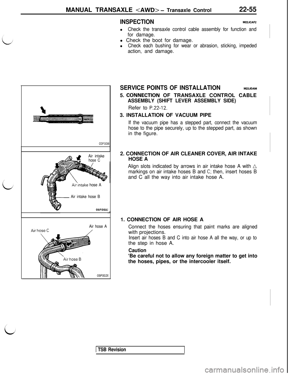
P.22-12.3. INSTALLATION OF VACUUM PIPE
If the vacuum pipe has a stepped part, connect the vacuum
hose to the pipe securely, up to the stepped part, as shownin the figure.
2. CONNECTION OF AIR CLEANER COVER, AIR INTAKE
HOSE A
Align slots indicated by arrows in air intake hose A with n
markings on air intake hoses B and C; then, insert hoses Band C all the way into air intake hose A.
1. CONNECTION OF AIR HOSE A
Connect the hoses ensuring that paint marks are alignedwith projections.
Insert air hoses B and C into air hose A all the way, or up tothe step in hose A.
Caution‘Be careful not to allow any foreign matter to get into
the hoses, pipes, or the intercooler itself.
1 TSB Revision
Page 438 of 1146
22-58
MANUAL TRANSAXLE
SERVICE POINTS OF REMOVALMPMBBB11. REMOVAL OF CLUTCH RELEASE CYLINDER
/ 12.
CONNECTION OF TRANSAXLE MOUNT
Refer to
PZ-15.‘L-J
18. DISCONNECTION OF TIE ROD END / 19. LOWER ARM
BALL JOINTRefer to
P.22-16.
23. REMOVAL OF DRIVE SHAFT (LEFT SIDE), INNER SHAFTASSEMBLY
/ 24. DRIVE SHAFT (RIGHT SIDE) / 27.
TRANSAXLE ASSEMBLY LOWER COUPLING BOLT / 28.
TRANSAXLE ASSEMBLYRefer to
P.22-16.
SERVICE POINTS OF INSTALLATIONM22MDAU24. INSTALLATION OF DRIVE SHAFT (RIGHT SIDE)
/ 15.
MOUNTING STOPPERRefer to
P.22-17.
03FOOE
Air intake hose B
05FOO23
Air hose A
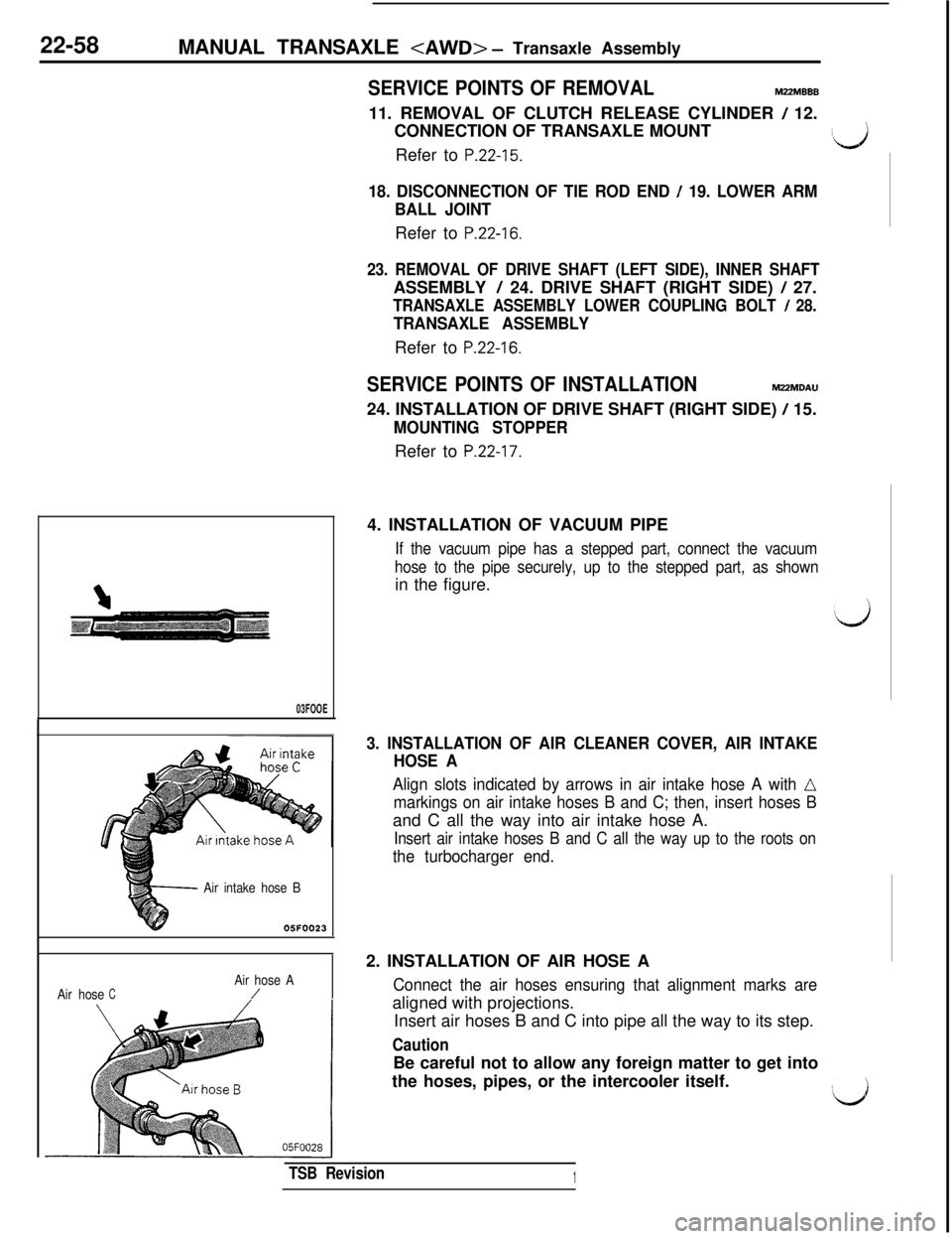
Air hoseC/4. INSTALLATION OF VACUUM PIPE
If the vacuum pipe has a stepped part, connect the vacuum
hose to the pipe securely, up to the stepped part, as shownin the figure.
3. INSTALLATION OF AIR CLEANER COVER, AIR INTAKE
HOSE A
Align slots indicated by arrows in air intake hose A with LI
markings on air intake hoses B and C; then, insert hoses Band C all the way into air intake hose A.
Insert air intake hoses B and C all the way up to the roots on
the turbocharger end.2. INSTALLATION OF AIR HOSE A
Connect the air hoses ensuring that alignment marks arealigned with projections.
Insert air hoses B and C into pipe all the way to its step.
CautionBe careful not to allow any foreign matter to get into
the hoses, pipes, or the intercooler itself.
#L.&J
TSB Revision1