engine MITSUBISHI 380 2005 Owners Manual
[x] Cancel search | Manufacturer: MITSUBISHI, Model Year: 2005, Model line: 380, Model: MITSUBISHI 380 2005Pages: 1500, PDF Size: 47.87 MB
Page 951 of 1500
THERMOSTAT
ENGINE COOLING14-36
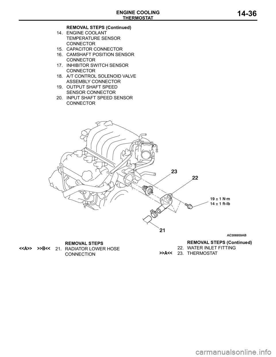
14. ENGINE COOLANT
TEMPERATURE SENSOR
CONNECTOR
15. CAPACITOR CONNECTOR
16. CAMSHAFT POSITION SENSOR
CONNECTOR
17. INHIBITOR SWITCH SENSOR
CONNECTOR
18. A/T CONTROL SOLENOID VALVE
ASSEMBLY CONNECTOR
19. OUTPUT SHAFT SPEED
SENSOR CONNECTOR
20. INPUT SHAFT SPEED SENSOR
CONNECTOR REMOVAL STEPS (Continued)
REMOVAL STEPS
<> >>B<<21. RADIATOR LOWER HOSE
CONNECTION22. WATER INLET FITTING>>A<<23. THERMOSTATREMOVAL STEPS (Continued)
Page 952 of 1500
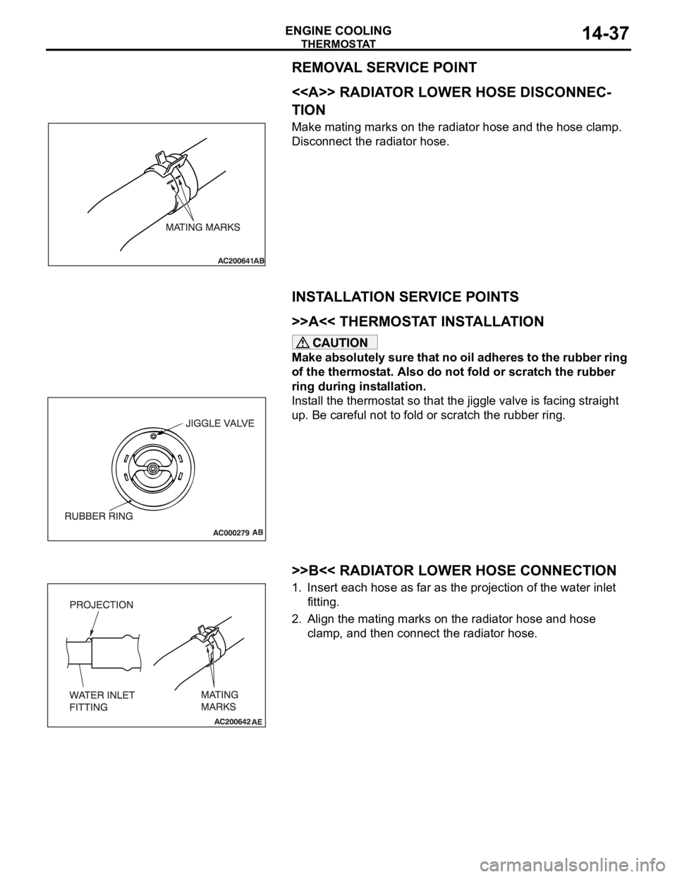
Page 953 of 1500
THERMOSTAT
ENGINE COOLING14-38
INSPECTIONM1141002500450.
Thermostat Check
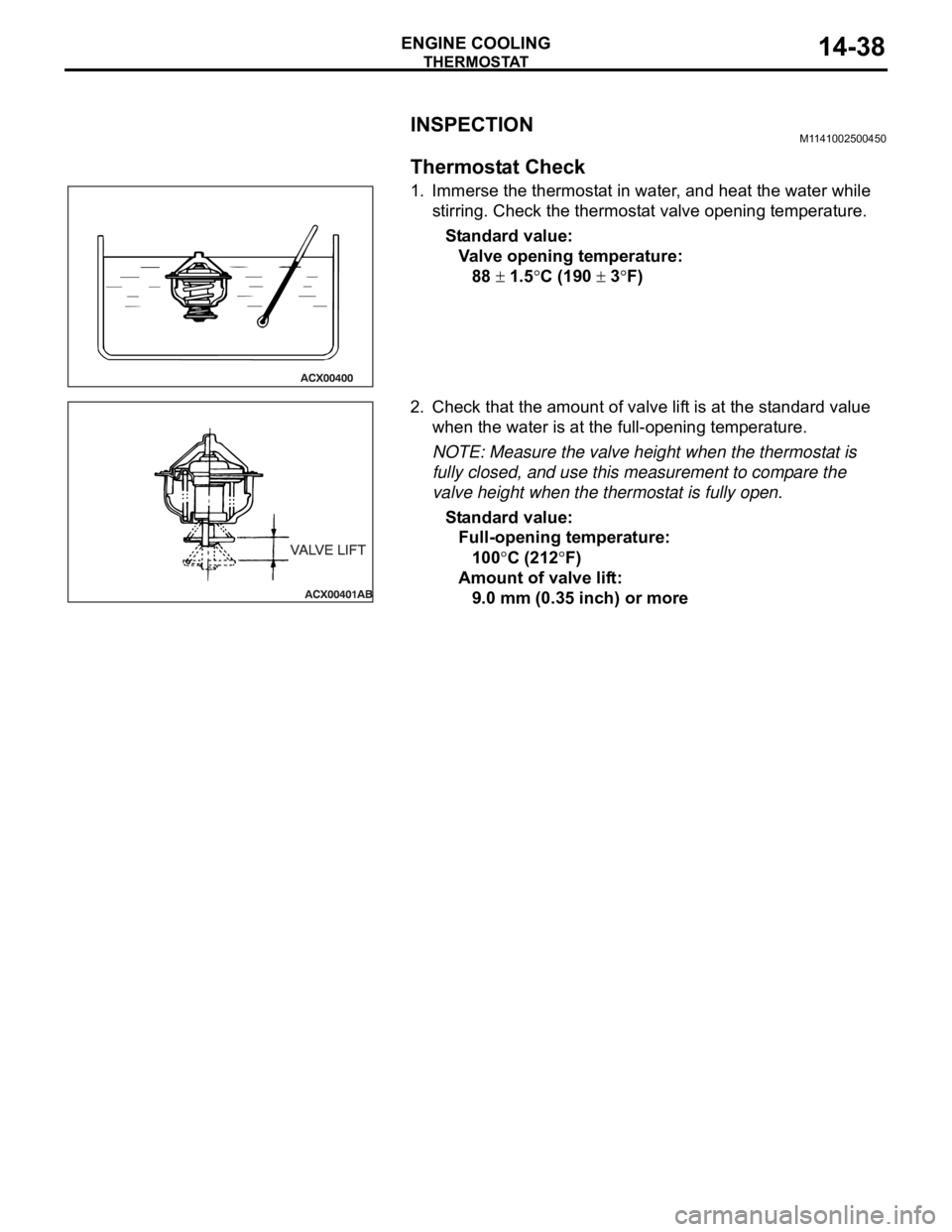
1. Immerse the thermostat in water, and heat the water while
stirring. Check the thermostat valve opening temperature.
Standard value:
Valve opening temperature:
88
1.5C (190 3F)
2. Check that the amount of valve lift is at the standard value
when the water is at the full-opening temperature.
NOTE: Measure the valve height when the thermostat is
fully closed, and use this measurement to compare the
valve height when the thermostat is fully open.
Standard value:
Full-opening temperature:
100
C (212F)
Amount of valve lift:
9.0 mm (0.35 inch) or more
Page 954 of 1500
WATE R P U M P
ENGINE COOLING14-39
WAT E R P U M P
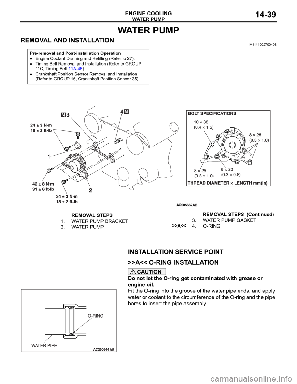
REMOVAL AND INSTALLATIONM1141002700498
INSTALLATION SERVICE POINT
.
>>A<< O-RING INSTALLATION
Do not let the O-ring get contaminated with grease or
engine oil.
Fit the O-ring into the groove of the water pipe ends, and apply
water or coolant to the circumference of the O-ring and the pipe
bores to insert the pipe assembly.
Pre-removal and Post-installation Operation
Engine Coolant Draining and Refilling (Refer to 27).
Timing Belt Removal and Installation (Refer to GROUP
11C, Timing Belt 11A-46).
Crankshaft Position Sensor Removal and Installation
(Refer to GROUP 16, Crankshaft Position Sensor 35).
REMOVAL STEPS
1. WATER PUMP BRACKET
2. WATER PUMP3. WATER PUMP GASKET
>>A<<4. O-RINGREMOVAL STEPS (Continued)
Page 955 of 1500
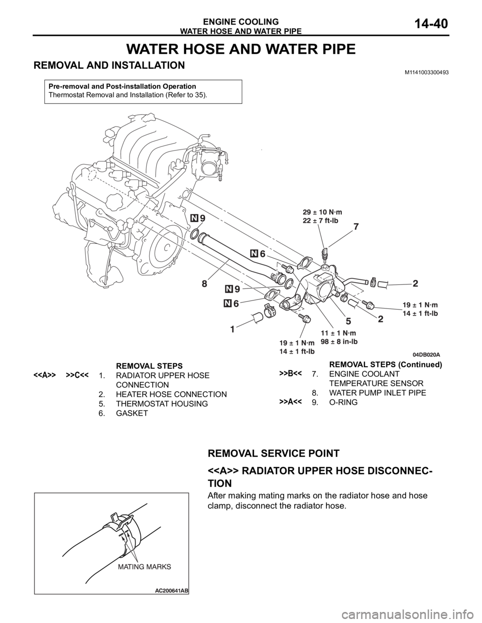
WATER HOSE AND WATER PIPE
ENGINE COOLING14-40
WATER HOSE AND WATER PIPE
REMOVAL AND INSTALLATIONM1141003300493
REMOVAL SERVICE POINT
.
<> RADIATOR UPPER HOSE DISCONNEC-
TION
After making mating marks on the radiator hose and hose
clamp, disconnect the radiator hose.
Pre-removal and Post-installation Operation
Thermostat Removal and Installation (Refer to 35).
REMOVAL STEPS
<> >>C<<1. RADIATOR UPPER HOSE
CONNECTION
2. HEATER HOSE CONNECTION
5. THERMOSTAT HOUSING
6. GASKET>>B<<7. ENGINE COOLANT
TEMPERATURE SENSOR
8. WATER PUMP INLET PIPE
>>A<<9. O-RINGREMOVAL STEPS (Continued)
Page 956 of 1500
WATER HOSE AND WATER PIPE
ENGINE COOLING14-41
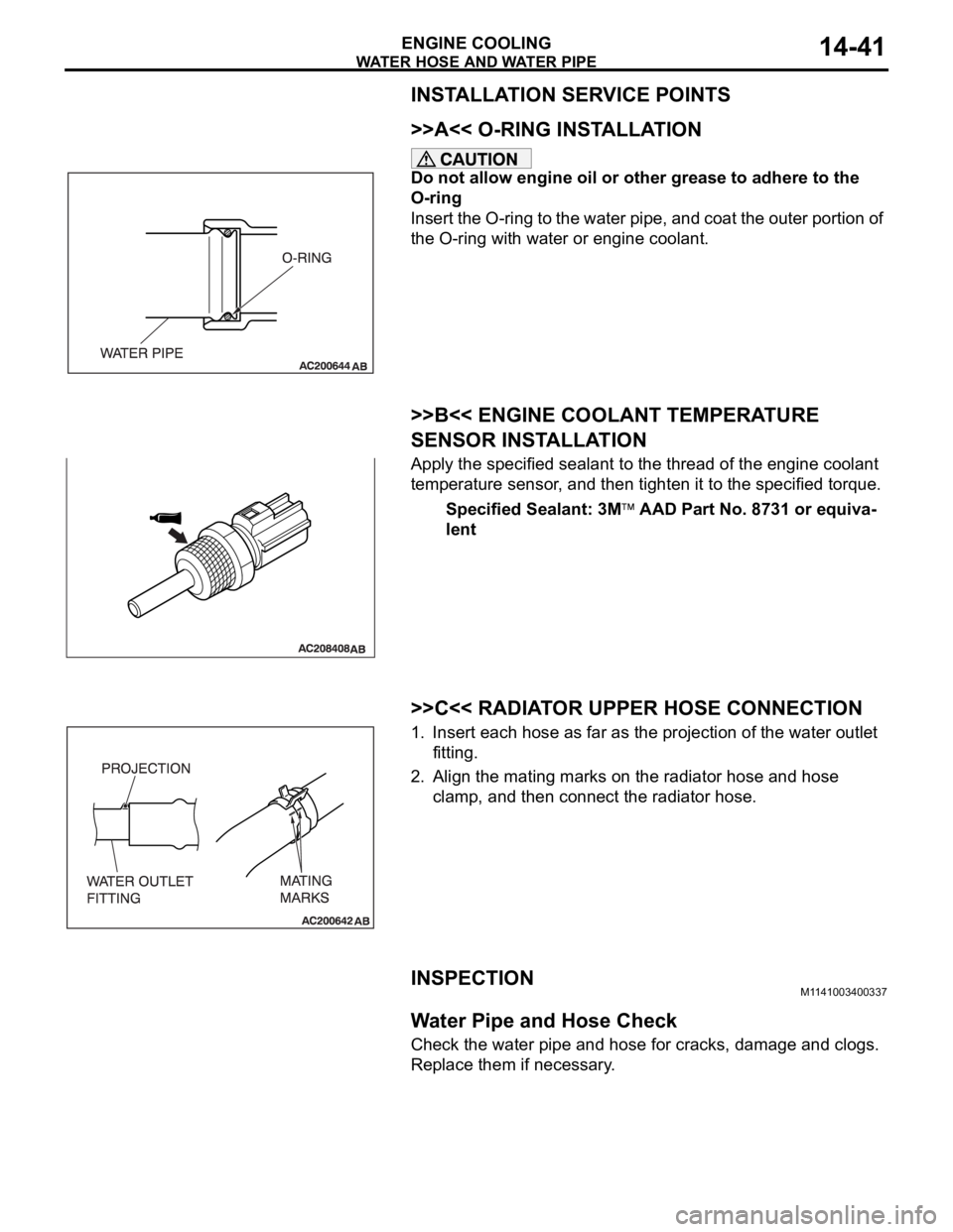
INSTALLATION SERVICE POINTS
.
>>A<< O-RING INSTALLATION
Do not allow engine oil or other grease to adhere to the
O-ring
Insert the O-ring to the water pipe, and coat the outer portion of
the O-ring with water or engine coolant.
.
>>B<< ENGINE COOLANT TEMPERATURE
SENSOR INSTALLATION
Apply the specified sealant to the thread of the engine coolant
temperature sensor, and then tighten it to the specified torque.
Specified Sealant: 3M
AAD Part No. 8731 or equiva-
lent
.
>>C<< RADIATOR UPPER HOSE CONNECTION
1. Insert each hose as far as the projection of the water outlet
fitting.
2. Align the mating marks on the radiator hose and hose
clamp, and then connect the radiator hose.
INSPECTIONM1141003400337.
Water Pipe and Hose Check
Check the water pipe and hose for cracks, damage and clogs.
Replace them if necessary.
Page 957 of 1500

SPECIFICATIONS
ENGINE COOLING14-42
SPECIFICATIONS
FASTENER TIGHTENING SPECIFICATIONSM1141005000346
ITEM SPECIFICATION
Cylinder block drain plug 39
5 Nm (29 3 ft-lb)
Radiator
Front end structure bar bolt M8
10 11 2 Nm (98 17 in-lb)
M8
20 22 4 Nm (16 3 ft-lb)
Thermostat
Control harness bolt 5.0
1.0 Nm (44 9 in-lb)
Grounding bolt M6 9.0
2.0 Nm (80 17 in-lb)
M8 22
4 Nm (16 3 ft-lb)
Water inlet fitting bolt 19
1 Nm (14 1 ft-lb)
Water hose and water pipe
Engine coolant temperature sensor 29
10 Nm
Thermostat housing bolt 19
1 Nm (14 1 ft-lb)
Water pump inlet pipe 11
1 Nm (98 8 ft-lb)
Water pump
Water pump bolt M8 42
8 Nm (31 6 ft-lb)
M10 24
3 Nm (18 2 ft-lb)
Water pump bracket bolt 24
3 Nm (18 2 ft-lb)
Page 958 of 1500

SPECIFICATIONS
ENGINE COOLING14-43
SERVICE SPECIFICATIONM1141000300449
CAPACITIESM1141005100138
SEALANTSM1141000500368
ITEM STANDARD VALUE LIMIT
Fan Controller V A/C OFF 1 or less -
A/C ON Repeat
8.2
2.6
System voltage
2.6-
High-pressure valve opening pressure of radiator cap kPa (psi) 93
123 (14 18) Minimum 83 (12)
Thermostat Valve opening temperature
of thermostat
C (F)3.8L Engine 88
1.5 (190 3)
-
Full-opening temperature
of thermostat
C (F)3.8L Engine 100 (212)
-
Valve lift mm (in) 3.8L Engine 9.0 (0.35) or more
-
ITEM
QUANTITY dm3 (qt)
Long life antifreeze coolant or an equivalent 3.8L Engine 8.7 (9.2)
ITEM SPECIFIED SEALANT
Cylinder block drain plug 3M
AAD Part No.8731 or equivalent
Engine coolant temperature sensor
Page 959 of 1500

SPECIFICATIONS
ENGINE COOLING14-44
Page 961 of 1500
GENERAL DESCRIPTION
INTAKE AND EXHAUST15-2
GENERAL DESCRIPTIONM1151000100446
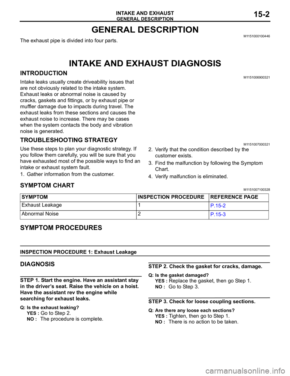
The exhaust pipe is divided into four parts.
INTAKE AND EXHAUST DIAGNOSIS
INTRODUCTIONM1151006900321
Intake leaks usually create driveability issues that
are not obviously related to the intake system.
Exhaust leaks or abnormal noise is caused by
cracks, gaskets and fittings, or by exhaust pipe or
muffler damage due to impacts during travel. The
exhaust leaks from these sections and causes the
exhaust noise to increase. There may be cases
when the system contacts the body and vibration
noise is generated.
TROUBLESHOOTING STRATEGYM1151007000321
Use these steps to plan your diagnostic strategy. If
you follow them carefully, you will be sure that you
have exhausted most of the possible ways to find an
intake or exhaust system fault.
1. Gather information from the customer.2. Verify that the condition described by the
customer exists.
3. Find the malfunction by following the Symptom
Chart.
4. Verify malfunction is eliminated.
SYMPTOM CHARTM1151007100328
SYMPTOM PROCEDURES
INSPECTION PROCEDURE 1: Exhaust Leakage
DIAGNOSIS
STEP 1. Start the engine. Have an assistant stay
in the driver’s seat. Raise the vehicle on a hoist.
Have the assistant rev the engine while
searching for exhaust leaks.
Q: Is the exhaust leaking?
YES :
Go to Step 2.
NO : The procedure is complete.
STEP 2. Check the gasket for cracks, damage.
Q: Is the gasket damaged?
YES :
Replace the gasket, then go Step 1.
NO : Go to Step 3.
STEP 3. Check for loose coupling sections.
Q: Are there any loose each sections?
YES :
Tighten, then go to Step 1.
NO : There is no action to be taken. SYMPTOM INSPECTION PROCEDURE REFERENCE PAGE
Exhaust Leakage 1
P.15-2
Abnormal Noise 2
P.15-3