engine MITSUBISHI 380 2005 Workshop Manual
[x] Cancel search | Manufacturer: MITSUBISHI, Model Year: 2005, Model line: 380, Model: MITSUBISHI 380 2005Pages: 1500, PDF Size: 47.87 MB
Page 962 of 1500
SPECIAL TOOLS
INTAKE AND EXHAUST15-3
INSPECTION PROCEDURE 2: Abnormal Noise
DIAGNOSIS
STEP 1. Start the engine. Have an assistant stay
in the drivers seat. Raise the vehicle on a hoist.
Have the assistant rev the engine while
searching for exhaust leaks.
Q: Is any abnormal noise generated?
YES :
Go to Step 2.
NO : The procedure is complete.
STEP 2. Check for missing parts in the muffler.
Tap the muffler lightly to check for loose baffles,
etc.
Q: Are there any missing parts in the muffler?
YES :
Replace, then go to Step 1.
NO : Go to Step 3.
STEP 3. Check the hanger for cracks.
Q: Is the hanger cracked?
YES :
Replace, then go to Step 1.
NO : Go to Step 4.
STEP 4. Check for interference of the pipes and
muffler with the body.
Q: Are the pipes and muffler interfering with the
body?
YES :
Repair, then go to Step 1.
NO : Go to Step 5.
STEP 5. Check the heat protectors.
Q: Are any heat protectors loose or damaged?
YES :
Tighten or replace, then go to Step 1.
NO : Go to Step 6.
STEP 6. Check the pipes and muffler for damage.
Q: Are the pipes and muffler damaged?
YES :
Replace, then go to Step 1.
NO : There is no action to be taken.
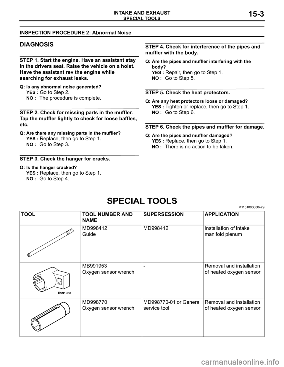
SPECIAL TOOLSM1151000600429
TOOL TOOL NUMBER AND
NAMESUPERSESSION APPLICATION
MD998412
GuideMD998412 Installation of intake
manifold plenum
MB991953
Oxygen sensor wrench- Removal and installation
of heated oxygen sensor
MD998770
Oxygen sensor wrenchMD998770-01 or General
service toolRemoval and installation
of heated oxygen sensor
Page 963 of 1500
AIR CLEANER
INTAKE AND EXHAUST15-4
AIR CLEANER
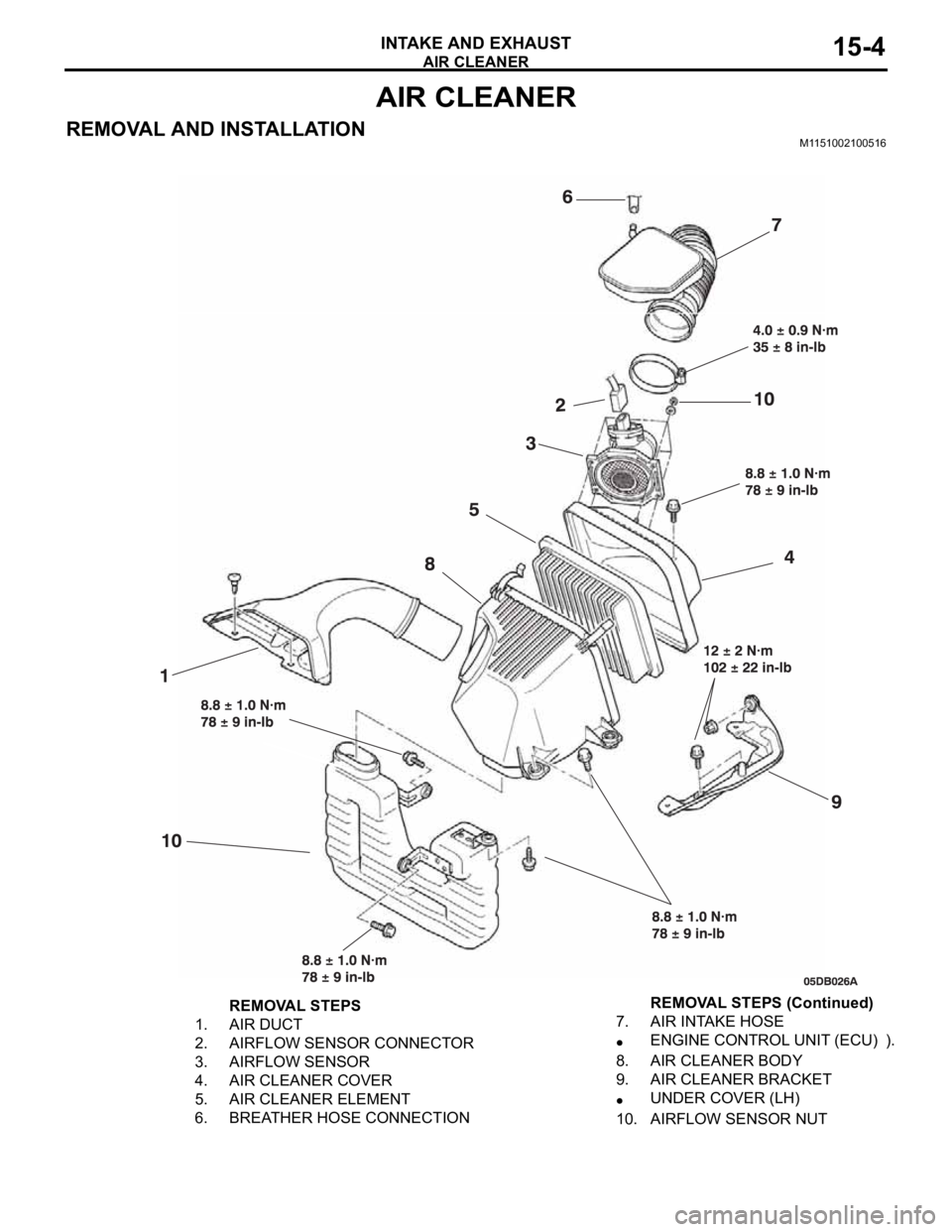
REMOVAL AND INSTALLATIONM1151002100516
REMOVAL STEPS
1. AIR DUCT
2. AIRFLOW SENSOR CONNECTOR
3. AIRFLOW SENSOR
4. AIR CLEANER COVER
5. AIR CLEANER ELEMENT
6. BREATHER HOSE CONNECTION7. AIR INTAKE HOSE
ENGINE CONTROL UNIT (ECU) ).
8. AIR CLEANER BODY
9. AIR CLEANER BRACKET
UNDER COVER (LH)
10. AIRFLOW SENSOR NUTREMOVAL STEPS (Continued)
Page 964 of 1500
INTAKE MANIFOLD PLENUM
INTAKE AND EXHAUST15-5
INTAKE MANIFOLD PLENUM
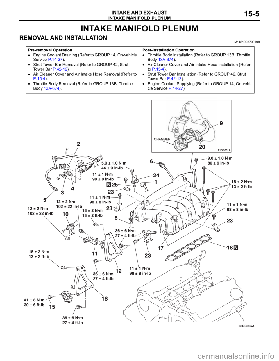
REMOVAL AND INSTALLATION M1151002700198
Pre-removal Operation
Engine Coolant Draining (Refer to GROUP 14, On-vehicle
Service P.14-27).
Strut Tower Bar Removal (Refer to GROUP 42, Strut
To w e r B a r P.42-12).
Air Cleaner Cover and Air Intake Hose Removal (Refer to
P.15-4).
Throttle Body Removal (Refer to GROUP 13B, Throttle
Body 13A-674).Post-installation Operation
Throttle Body Installation (Refer to GROUP 13B, Throttle
Body 13A-674).
Air Cleaner Cover and Air Intake Hose Installation (Refer
to P.15-4).
Strut Tower Bar Installation (Refer to GROUP 42, Strut
Tower Bar P.42-12).
Engine Coolant Supplying (Refer to GROUP 14, On-vehi-
cle Service P.14-27).
Page 966 of 1500
INTAKE MANIFOLD
INTAKE AND EXHAUST15-7
INTAKE MANIFOLD
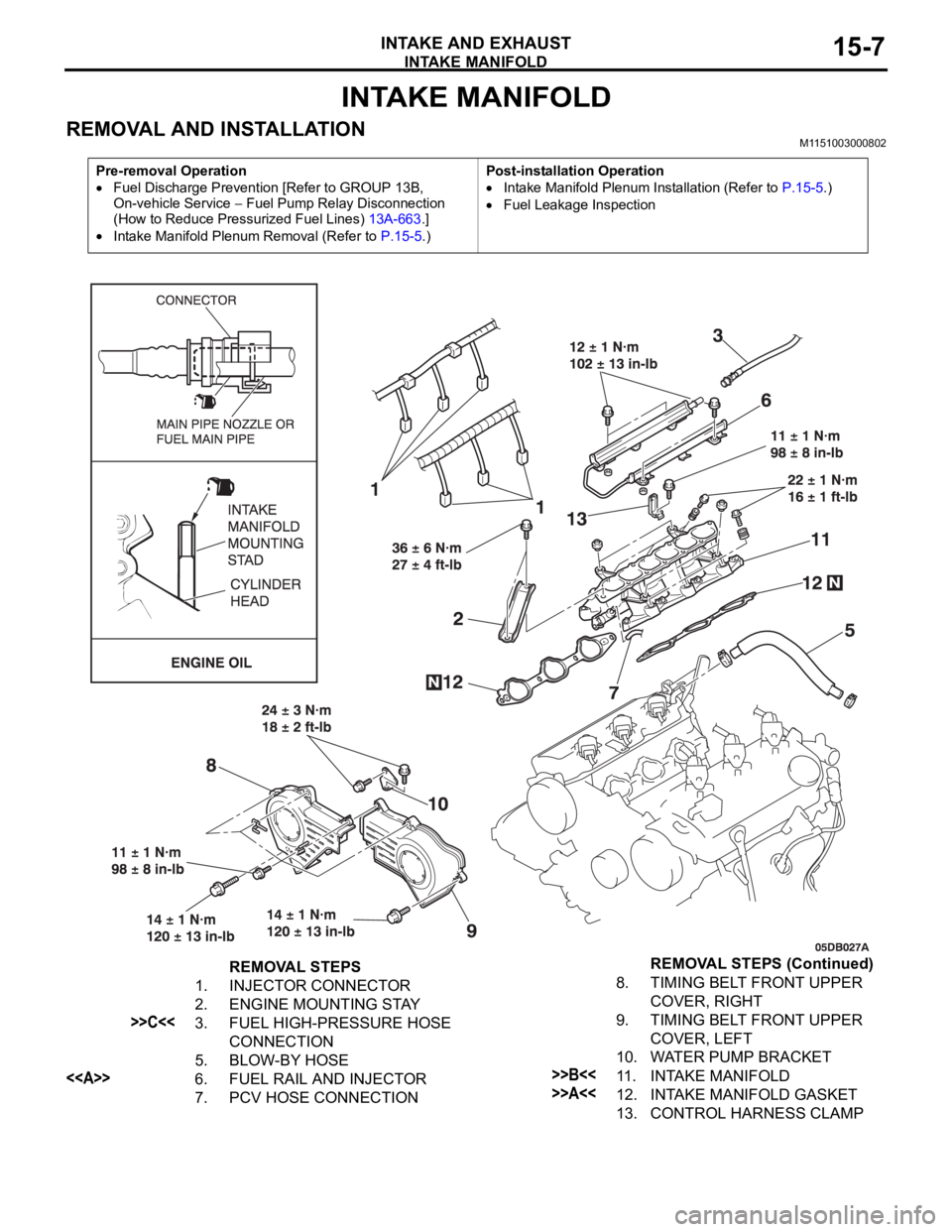
REMOVAL AND INSTALLATION M1151003000802
Pre-removal Operation
Fuel Discharge Prevention [Refer to GROUP 13B,
On-vehicle Service
Fuel Pump Relay Disconnection
(How to Reduce Pressurized Fuel Lines) 13A-663.]
Intake Manifold Plenum Removal (Refer to P.15-5.)Post-installation Operation
Intake Manifold Plenum Installation (Refer to P.15-5.)
Fuel Leakage Inspection
REMOVAL STEPS
1. INJECTOR CONNECTOR
2. ENGINE MOUNTING STAY
>>C<<3. FUEL HIGH-PRESSURE HOSE
CONNECTION
5. BLOW-BY HOSE
<>6. FUEL RAIL AND INJECTOR
7. PCV HOSE CONNECTION8. TIMING BELT FRONT UPPER
COVER, RIGHT
9. TIMING BELT FRONT UPPER
COVER, LEFT
10. WATER PUMP BRACKET>>B<<11. INTAKE MANIFOLD
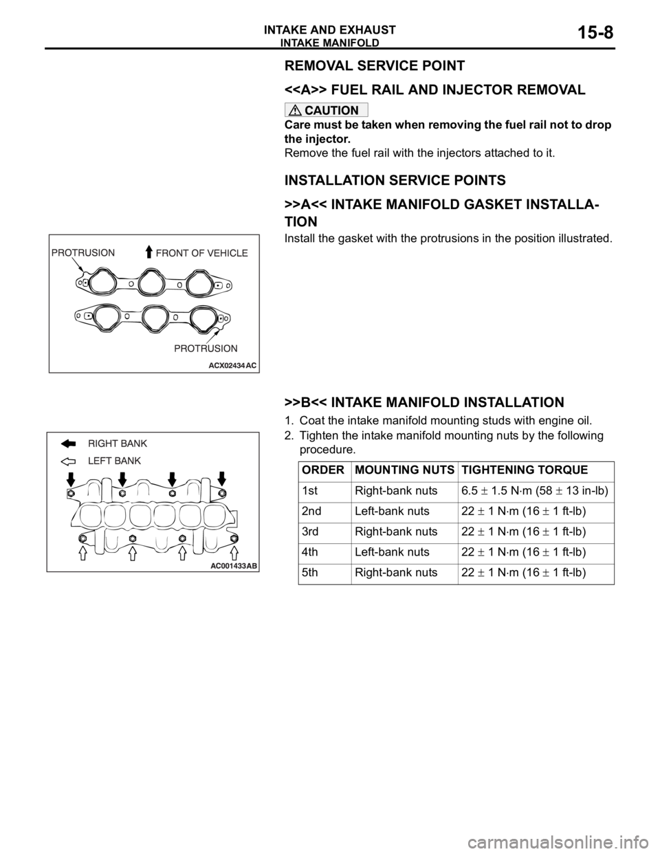
>>A<<12. INTAKE MANIFOLD GASKET
13. CONTROL HARNESS CLAMPREMOVAL STEPS (Continued)
Page 967 of 1500
Page 968 of 1500
INTAKE MANIFOLD
INTAKE AND EXHAUST15-9
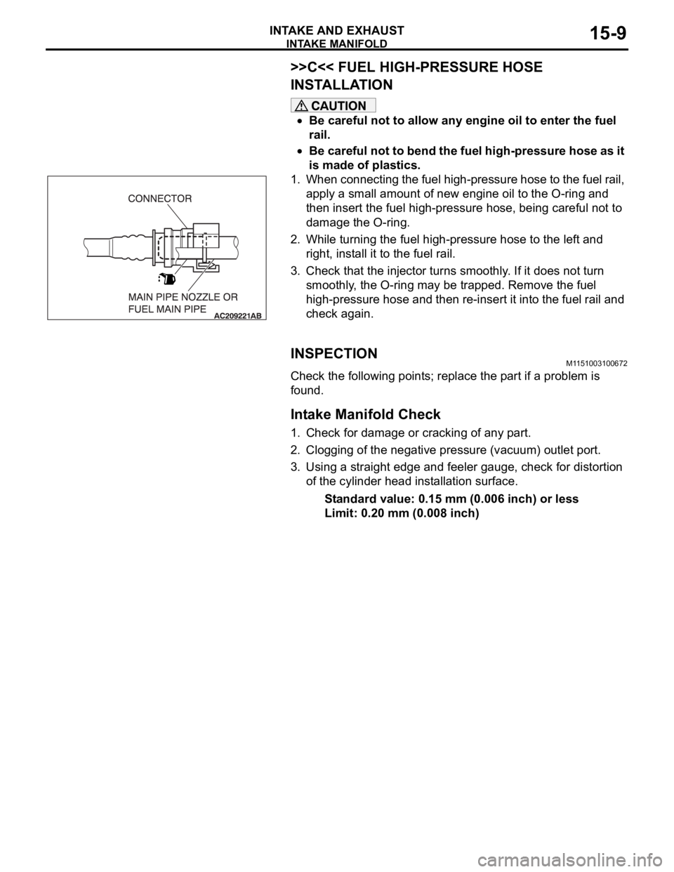
>>C<< FUEL HIGH-PRESSURE HOSE
INSTALLATION
Be careful not to allow any engine oil to enter the fuel
rail.
Be careful not to bend the fuel high-pressure hose as it
is made of plastics.
1. When connecting the fuel high-pressure hose to the fuel rail,
apply a small amount of new engine oil to the O-ring and
then insert the fuel high-pressure hose, being careful not to
damage the O-ring.
2. While turning the fuel high-pressure hose to the left and
right, install it to the fuel rail.
3. Check that the injector turns smoothly. If it does not turn
smoothly, the O-ring may be trapped. Remove the fuel
high-pressure hose and then re-insert it into the fuel rail and
check again.
INSPECTIONM1151003100672
Check the following points; replace the part if a problem is
found.
.
Intake Manifold Check
1. Check for damage or cracking of any part.
2. Clogging of the negative pressure (vacuum) outlet port.
3. Using a straight edge and feeler gauge, check for distortion
of the cylinder head installation surface.
Standard value: 0.15 mm (0.006 inch) or less
Limit: 0.20 mm (0.008 inch)
Page 970 of 1500
EXHAUST MANIFOLD
INTAKE AND EXHAUST15-11
Required Special Tools:
MB991953: Oxygen Sensor WrenchMD998770: Oxygen Sensor Wrench
Pre-removal and Post-installation Operation
Air Cleaner Cover and Air Intake Duct Removal and
Installation (Refer to P.15-4).
Battery Removal and Installation
Under Cover Removal and Installation (Refer to GROUP
51, Under Cover P.51-13).
Front Exhaust Pipe, Center Exhaust Pipe Removal and
Installation (Refer to P.15-14).
Strut Tower Bar Removal and Installation (Refer to
GROUP 42, Strut Tower Bar P.42-12).
Engine Coolant Draining and Refilling (Refer to GROUP
14, On-vehicle Service Engine Coolant Replacement
P.14-27).
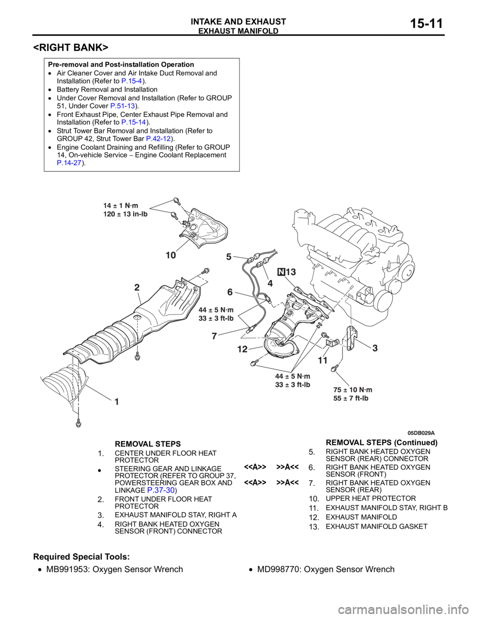
REMOVAL STEPS
1.
CENTER UNDER FLOOR HEAT
PROTECTOR
STEERING GEAR AND LINKAGE
PROTECTOR (REFER TO GROUP 37,
POWERSTEERING GEAR BOX AND
LINKAGE
P.37-30)
2.FRONT UNDER FLOOR HEAT
PROTECTOR
3.EXHAUST MANIFOLD STAY, RIGHT A
4.RIGHT BANK HEATED OXYGEN
SENSOR (FRONT) CONNECTOR
5.RIGHT BANK HEATED OXYGEN
SENSOR (REAR) CONNECTOR
<> >>A<<6.RIGHT BANK HEATED OXYGEN
SENSOR (FRONT)
<> >>A<<7.RIGHT BANK HEATED OXYGEN
SENSOR (REAR)
10.UPPER HEAT PROTECTOR
11 .EXHAUST MANIFOLD STAY, RIGHT B
12.EXHAUST MANIFOLD
13.EXHAUST MANIFOLD GASKET
REMOVAL STEPS (Continued)
Page 975 of 1500

SPECIFICATIONS
INTAKE AND EXHAUST15-16
SPECIFICATIONS
FASTENER TIGHTENING SPECIFICATIONSM1151006800506
ITEMSPECIFICATION
Air cleaner
Air cleaner bolt 8.8
1.0 Nm (78 9 in-lb)
Air cleaner bracket bolt and nut 12
2 Nm (102 22 in-lb)
Air cleaner resonator bolt 8.8
1.0 Nm (78 9 in-lb)
Air intake hose clamp bolt 4.0
0.9 Nm (35 8 in-lb)
Airflow sensor nut 8.0
1.0 Nm
Exhaust manifold
Exhaust manifold nut 44
5 Nm (33 3 ft-lb)
Front exhaust pipe bolt 49
9 Nm (37 6 ft-lb)
Exhaust manifold stay, left A bolt M8 19
3 Nm (14 2 ft-lb)
Exhaust manifold stay, left B bolt M10 44
8 Nm (33 5 ft-lb)
Heat protector bolt 14
1 Nm (120 13 in-lb)
Heated oxygen sensor 44
5 Nm (33 3 ft-lb)
Exhaust manifold
Exhaust manifold nut 44
5 Nm (33 3 ft-lb)
Exhaust manifold stay, right A bolt M12 75
10 Nm (55 7 ft-lb)
Exhaust manifold stay, right B bolt M10 44
5 Nm (33 3 ft-lb)
Heat protector bolt 14
1 Nm (120 13 in-lb)
Heated oxygen sensor 44
5 Nm (33 3 ft-lb)
Exhaust pipe and main muffler
Crossmember stay bolt 45
5 Nm (34 3 ft-lb)
Center exhaust pipe nut 49
9 Nm (37 6 ft-lb)
Front floor backbone brace bolt 22
4 Nm (16 3 ft-lb)
Front no.1 exhaust pipe bolt 35
4 Nm (26 3 ft-lb)
Front no.1 exhaust pipe to front no.2 exhaust pipe bolt 49
4 Nm (37 3 ft-lb)
Front no.1 exhaust pipe to right bank exhaust manifold nut 49
9 Nm (37 6 ft-lb)
Front no.1 exhaust pipe to left bank exhaust manifold bolt 49
9 Nm (37 6 ft-lb)
Hanger bolt 12
2 Nm (107 17 in-lb)
Main muffler bolt 49
4 Nm (37 3 ft-lb)
Heat protector bolt 14
1 Nm (120 13 in-lb)
Intake manifold
Control harness clamp bolt 11
1 Nm (98 8 in-lb)
Engine mounting stay bolt 36
6 Nm (27 4 ft-lb)
Fuel rail and injector bolt 12
1 Nm (102 13 in-lb)
Intake manifold bolt 22
1 Nm (16 1 ft-lb)
Timing belt front upper cover bolt M6 11
1 Nm (98 8 in-lb)
M8 14
1 Nm (120 13 in-lb)
Page 978 of 1500
16-1
GROUP 16
ENGINE
ELECTRICAL
CONTENTS
CHARGING SYSTEM . . . . . . . .
16-2
GENERAL DESCRIPTION . . . . . .
16-2
CHARGING SYSTEM DIAGNOSIS16-3
SPECIAL TOOL . . . . . . . . . . . . . . .16-6
ON-VEHICLE SERVICE. . . . . . . . .16-7
ALTERNATOR OUTPUT WIRE VOLTAGE
DROP TEST . . . . . . . . . . . . . . . . . . . . . 16-7
OUTPUT CURRENT TEST . . . . . . . . . . 16-8
REGULATED VOLTAGE TEST . . . . . . . 16-10
WAVE PATTERN CHECK USING AN
OSCILLOSCOPE . . . . . . . . . . . . . . . . . . 16-11
ALTERNATOR ASSEMBLY . . . . .16-14
REMOVAL AND INSTALLATION . . . . . 16-14
DISASSEMBLY AND ASSEMBLY. . . . . 16-15
INSPECTION . . . . . . . . . . . . . . . . . . . . . 16-17
STARTING SYSTEM . . . . . . . . .16-20
GENERAL DESCRIPTION . . . . . .
16-20
STARTING SYSTEM DIAGNOSIS . . . . 16-21
STARTER MOTOR ASSEMBLY . .16-23
REMOVAL AND INSTALLATION . . . . . 16-23
INSPECTION . . . . . . . . . . . . . . . . . . . . . 16-24
DISASSEMBLY AND ASSEMBLY. . . . . 16-26
INSPECTION . . . . . . . . . . . . . . . . . . . . . 16-28
IGNITION SYSTEM . . . . . . . . . . . . . .16-30GENERAL DESCRIPTION . . . . . . .
16-30
SPECIAL TOOLS . . . . . . . . . . . . . .16-30
ON-VEHICLE SERVICE . . . . . . . . .16-31
KNOCK CONTROL SYSTEM CHECK . . 16-31
IGNITION COIL CHECK. . . . . . . . . . . . . 16-31
SPARK PLUG TEST . . . . . . . . . . . . . . . 16-32
SPARK PLUG CHECK AND CLEANING16-32
CAMSHAFT POSITION SENSOR CHECK16-32
CRANKSHAFT POSITION SENSOR
CHECK . . . . . . . . . . . . . . . . . . . . . . . . . . 16-32
IGNITION COIL . . . . . . . . . . . . . . . .16-33
REMOVAL AND INSTALLATION . . . . . 16-33
CAMSHAFT POSITION SENSOR .16-34
REMOVAL AND INSTALLATION . . . . . 16-34
CRANKSHAFT POSITION SENSOR16-35
REMOVAL AND INSTALLATION . . . . . 16-35
KNOCK SENSOR . . . . . . . . . . . . . .16-36
REMOVAL AND INSTALLATION . . . . . 16-36
SPECIFICATIONS . . . . . . . . . . 16-38
FASTENER TIGHTENING
SPECIFICATIONS . . . . . . . . . . . . .
16-38
GENERAL SPECIFICATIONS . . . .16-38
SERVICE SPECIFICATIONS . . . . .16-39
Page 979 of 1500
16-2
CHARGING SYSTEM
GENERAL DESCRIPTIONM1161000100629
The charging system charges the battery with the
alternator output to keep the battery charged at a
constant level during varying electrical load.
OPERATION
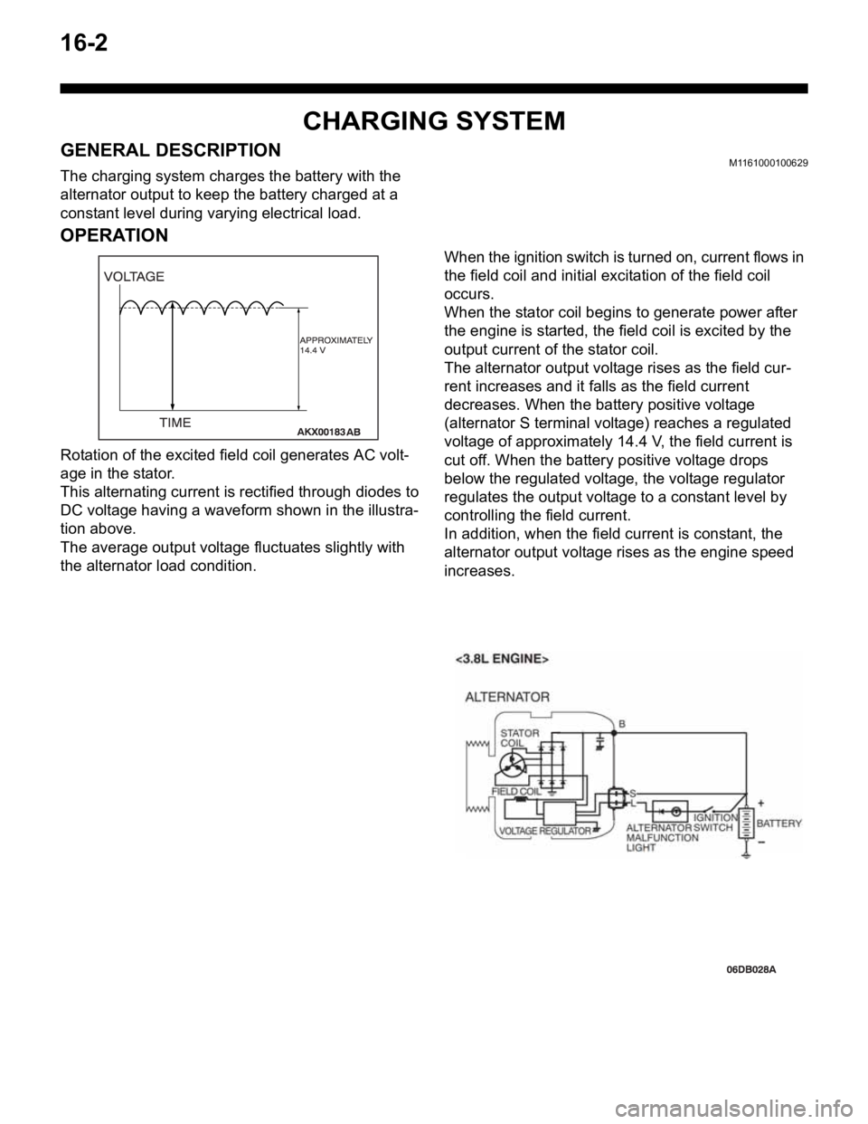
Rotation of the excited field coil generates AC volt-
age in the stator.
This alternating current is rectified through diodes to
DC voltage having a waveform shown in the illustra-
tion above.
The average output voltage fluctuates slightly with
the alternator load condition.When the ignition switch is turned on, current flows in
the field coil and initial excitation of the field coil
occurs.
When the stator coil begins to generate power after
the engine is started, the field coil is excited by the
output current of the stator coil.
The alternator output voltage rises as the field cur-
rent increases and it falls as the field current
decreases. When the battery positive voltage
(alternator S terminal voltage) reaches a regulated
voltage of approximately 14.4 V, the field current is
cut off. When the battery positive voltage drops
below the regulated voltage, the voltage regulator
regulates the output voltage to a constant level by
controlling the field current.
In addition, when the field current is constant, the
alternator output voltage rises as the engine speed
increases.