Ignition MITSUBISHI 380 2005 Workshop Manual
[x] Cancel search | Manufacturer: MITSUBISHI, Model Year: 2005, Model line: 380, Model: MITSUBISHI 380 2005Pages: 1500, PDF Size: 47.87 MB
Page 1099 of 1500
DOOR
BODY42-32
GLASS SLIDING MECHANISM CHECK AND
ADJUSTMENT
M1429000900109
If the window glass automatically starts moving downwards at
the wrong time while it is being raised, carry out the following
adjustment or replacement procedures.
1. Remove the door trim assembly (Refer to GROUP 52A,
Door trim P.52A-14).
2. Remove the waterproof film (Refer to P.42-52).
Insert a cushion or similar object to prevent damage to the
glass if it should fall.
3. Remove the window regulator assembly from the door
window glass, and then raise and lower the door window
glass by hand to check the operation force.
4. If the door window glass does not move up and down
smoothly, check or repair the following points:
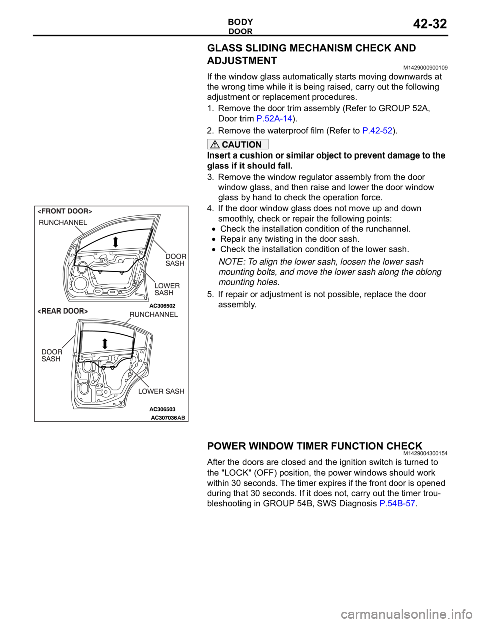
Check the installation condition of the runchannel.
Repair any twisting in the door sash.
Check the installation condition of the lower sash.
NOTE: To align the lower sash, loosen the lower sash
mounting bolts, and move the lower sash along the oblong
mounting holes.
5. If repair or adjustment is not possible, replace the door
assembly.
POWER WINDOW TIMER FUNCTION CHECKM1429004300154
After the doors are closed and the ignition switch is turned to
the "LOCK" (OFF) position, the power windows should work
within 30 seconds. The timer expires if the front door is opened
during that 30 seconds. If it does not, carry out the timer trou-
bleshooting in GROUP 54B, SWS Diagnosis P.54B-57.
Page 1135 of 1500
KEYLESS ENTRY SYSTEM
BODY42-68
If none of the doors is opened or the ignition key
is not inserted in the ignition switch within 30 sec-
onds after the doors are unlocked using the
transmitter, the ETACS-ECU will relock the doors
automatically. This is called "Timer lock function."
This timer lock function prevents accidental
unlocking of doors. The adjustment function
allows you to change the timer lock period from 30 seconds (default setting) to 60, 120 or 180
seconds. For further details on using the
multi-center display (middle grade type) to adjust
the timer lock period, refer to GROUP 54B,
On-vehicle Service P.54B-486.
NOTE: The timer lock period begins when the doors
are unlocked, and ends when the doors is relocked
automatically.
KEYLESS ENTRY SYSTEM DIAGNOSISBGBCJGAI
The keyless entry system is controlled by the Simpli-
fied Wiring System (SWS). Refer to GROUP 54B,
SWS Diagnosis P.54B-57.
SPECIAL TOOLBGBBBGDH
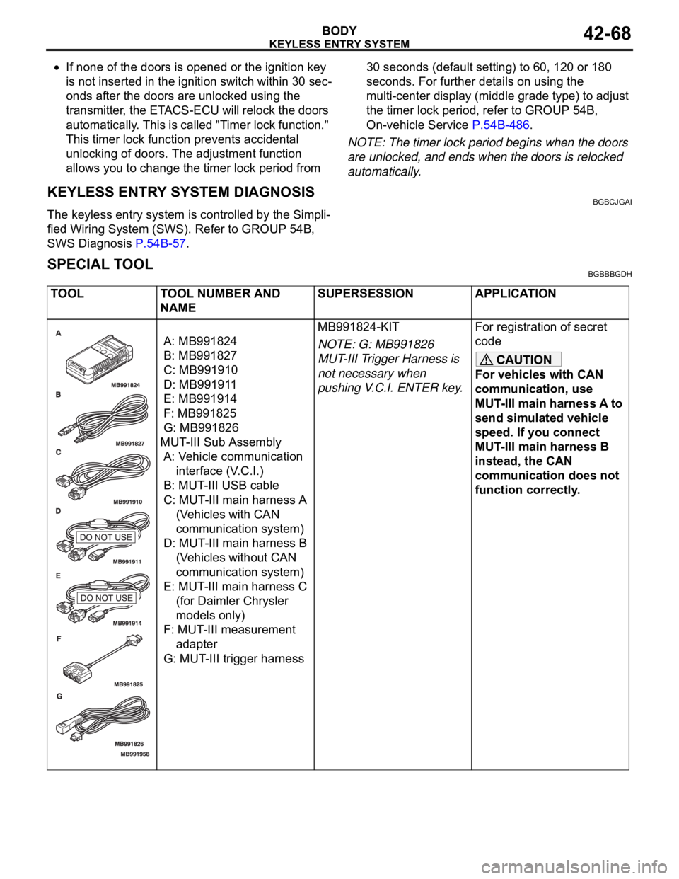
TOOL TOOL NUMBER AND
NAMESUPERSESSION APPLICATION
A: MB991824
B: MB991827
C: MB991910
D: MB991911
E: MB991914
F: MB991825
G: MB991826
MUT-III Sub Assembly
A: Vehicle communication
interface (V.C.I.)
B: MUT-III USB cable
C: MUT-III main harness A
(Vehicles with CAN
communication system)
D: MUT-III main harness B
(Vehicles without CAN
communication system)
E: MUT-III main harness C
(for Daimler Chrysler
models only)
F: MUT-III measurement
adapter
G: MUT-III trigger harnessMB991824-KIT
NOTE: G: MB991826
MUT-III Trigger Harness is
not necessary when
pushing V.C.I. ENTER key.For registration of secret
code
For vehicles with CAN
communication, use
MUT-III main harness A to
send simulated vehicle
speed. If you connect
MUT-III main harness B
instead, the CAN
communication does not
function correctly.
Page 1138 of 1500

KEYLESS ENTRY SYSTEM
BODY42-71
KEYLESS ENTRY SYSTEM INSPECTIONBGBHCDAE
Check the following items. If defective, refer to GROUP 54B,
SWS Diagnosis P.54B-10).
1. Operate the transmitter to check that the doors can be
locked and unlocked.
NOTE: The adjustment function allows you to change the
unlock operation setting as follows. Prior to that check, con-
firm which setting is activated.
.
a. When the unlock button is pressed once, the driver's
door will be unlocked. Then when the button is pressed
once again, all the doors will be opened (initial setting).
b. When the unlock button is pressed only once, all the
doors will be opened.
2. Press the trunk lid button of transmitter twice (press once,
and then press again within 5 seconds) and confirm that the
trunk lid opens.
3. Operate the transmitter to check that the answerback
function works in response to doors locking/unlocking.
NOTE: The adjustment function allows you to change the
hazard answerback setting as follows. Prior to that check,
confirm which setting is activated.
.
a. Turn-signal lights: Flash once when doors are locked,
and twice when unlocked (initial setting)
b. Turn-signal lights: Flash once when doors are locked,
but does not flash when unlocked.
c. Turn-signal lights: Do not flash when doors are locked,
but flash twice when unlocked.
d. Turn-signal lights: Do not flash when doors are locked
and unlocked.
NOTE: The adjustment function allows you to change the
horn answerback setting as follows. Prior to that check, con-
firm which setting is activated.
.
a. Horn: Sounds once when the lock button is pressed.
b. Horn: Sounds once when the lock button is pressed (ini-
tial setting).
c. Horn: Does not sound.
KEYLESS ENTRY SYSTEM TIMER LOCK
FUNCTION INSPECTION
BGBEBDIA
If the doors are not locked within 30 seconds after the unlock
button is pressed, refer to GROUP 54B, SWS Diagnosis
P.54B-10.
NOTE: If either of the doors is opened or the key is inserted in
the ignition switch within that 30-second period, the timer lock
function will be cancelled.
Page 1139 of 1500

KEYLESS ENTRY SYSTEM
BODY42-72
NOTE: The adjustment function allows you to change the timer
lock period from 30 seconds (initial setting) to 60, 120 or 180
seconds. Prior to this inspection, confirm which setting is acti-
vated.
ENABLING/DISABLING THE ANSWERBACK
FUNCTION
BGBDGCGD
When the doors are locked or unlocked by using the transmit-
ter, the dome light will flash/illuminate, the turn-signal lights will
flash (hazard answerback), or the horn will sound (horn
answerback) to inform the driver.
The hazard answerback and horn answerback functions can be
enabled or disabled according to the following procedure:
ENABLING/DISABLING THE HAZARD
ANSWERBACK FUNCTION
.
How to adjust hazard answerback when the trans-
mitter is used to lock doors
1. Remove the ignition key.
2. Push the ”unlock” button and then push the ”lock“ button
within 4 seconds to 10 seconds.
3. Release the ”lock” button within 10 seconds after Step 2 and
then release the “unlock” button. The ETACS-ECU tone
alarm will sound, indicating that the hazard answerback
function can be enabled or disabled when the doors are
locked.
Enable the hazard answerback function when the
doors are locked: The ETACS-ECU tone alarm will
sound once.
Disable the hazard answerback function when the
doors are locked: The ETACS-ECU tone alarm will
sound twice.
.
How to adjust hazard answerback when the
transmitter is used to unlock doors
1. Remove the ignition key.
2. Push the ”unlock” button and then push the ”lock“ button
within 4 seconds to 10 seconds.
3. Release the ”lock” button within 10 seconds after Step 2 and
then release the “unlock” button. The ETACS-ECU tone
alarm will sound, indicating that the hazard answerback
function can be enabled or disabled when the door are
unlocked.
Enable the hazard answerback function when the
doors are unlocked: The ETACS-ECU tone alarm
will sound once.
Disable the hazard answerback function when the
doors are unlocked: The ETACS-ECU tone alarm
will sound twice.
Page 1140 of 1500

KEYLESS ENTRY SYSTEM
BODY42-73
ENABLING/DISABLING THE HORN
ANSWERBACK FUNCTION
.
1. Remove the ignition key.
2. Push the ”unlock” button and then push the ”lock“ button
within 4 seconds to 10 seconds.
3. Release the ”lock” button within 10 seconds after Step 2 and
then release the “unlock” button. The ETACS-ECU tone
alarm will sound, indicating that the horn answerback
function can be enabled or disabled.
Enable the horn answerback function*: The
ETACS-ECU tone alarm will sound once.
Disable the horn answerback function: The
ETACS-ECU tone alarm will sound twice.
Enable the horn answerback function**: The
ETACS-ECU tone alarm will sound three times.
NOTE: .
*: The horn will sound if "LOCK" button is pressed with the
doors locked.
**: The horn will sound if the doors are locked with the key-
less entry system.
HOW TO REGISTER SECRET CODEBGBHCCCB
Required Special Tools:
: MUT-III Sub Assembly
MB991824: Vehicle Communication Interface (V.C.I.)
MB991910: MUT-III Main harness A
Each individual secret code is registered inside the transmitter,
and so it is necessary to resister these codes with the
EEPROM inside the receiver in the following cases.
When the transmitter or ETACS-ECU is replaced
If more transmitters are to be used
If it appears that a problem is occurring because of faulty
registration of a code.
A maximum of four different codes can be stored in the
EEPROM memory (four different transmitters can be used).
When the code for the first transmitter is registered, the previ-
ously registered codes for all transmitters are cleared. There-
fore, if you are using four transmitters or are adding more
transmitters, the codes for all transmitters must be registered at
the same time.
WHEN SPECIAL TOOL MB991824 (V.C.I.) IS USED
.
1. Check that the doors lock normally when the key is used.
2. Insert the ignition key.
Page 1141 of 1500
KEYLESS ENTRY SYSTEM
BODY42-74
To prevent damage to special tool MB991824 (V.C.I.),
always turn the ignition switch to “LOCK” (OFF) position
before connecting or disconnecting special tool MB991824
(V.C.I.).
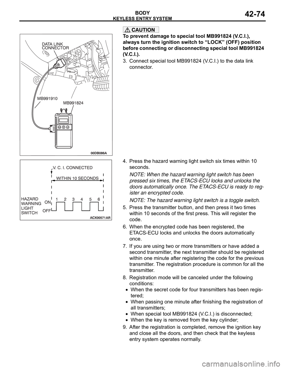
3. Connect special tool MB991824 (V.C.I.) to the data link
connector.
4. Press the hazard warning light switch six times within 10
seconds.
NOTE: When the hazard warning light switch has been
pressed six times, the ETACS-ECU locks and unlocks the
doors automatically once. The ETACS-ECU is ready to reg-
ister an encrypted code.
NOTE: The hazard warning light switch is a toggle switch.
5. Press the transmitter button, and then press it two times
within 10 seconds of the first press. This will register the
code.
6. When the encrypted code has been registered, the
ETACS-ECU locks and unlocks the doors automatically
once.
7. If you are using two or more transmitters or have added a
second transmitter, the next transmitter should be registered
within one minute after registering the code for the previous
transmitter. The registration procedure is common for all the
transmitter.
8. Registration mode will be canceled under the following
conditions:
When the secret code for four transmitters has been regis-
tered;
When passing one minute after finishing the registration of
all transmitters;
When special tool MB991824 (V.C.I.) is disconnected;
When the key is removed from the key cylinder;
9. After the registration is completed, remove the ignition key
and close all the doors, and then check that the keyless
entry system operates normally.
Page 1143 of 1500
SUNROOF ASSEMBLY
BODY42-76
SUNROOF TIMER FUNCTION CHECKM1426004300100
Keep the door closed, turn OFF the ignition switch and check to
see if the sunroof can be operated for 30 seconds after that. If
not, perform troubleshooting (Refer to GROUP 54B, SWS
Diagnosis P.54B-57).
SUNROOF FIT ADJUSTMENTM1426001000285
1. Fully close the roof lid glass.
2. Fully open the sunshade.
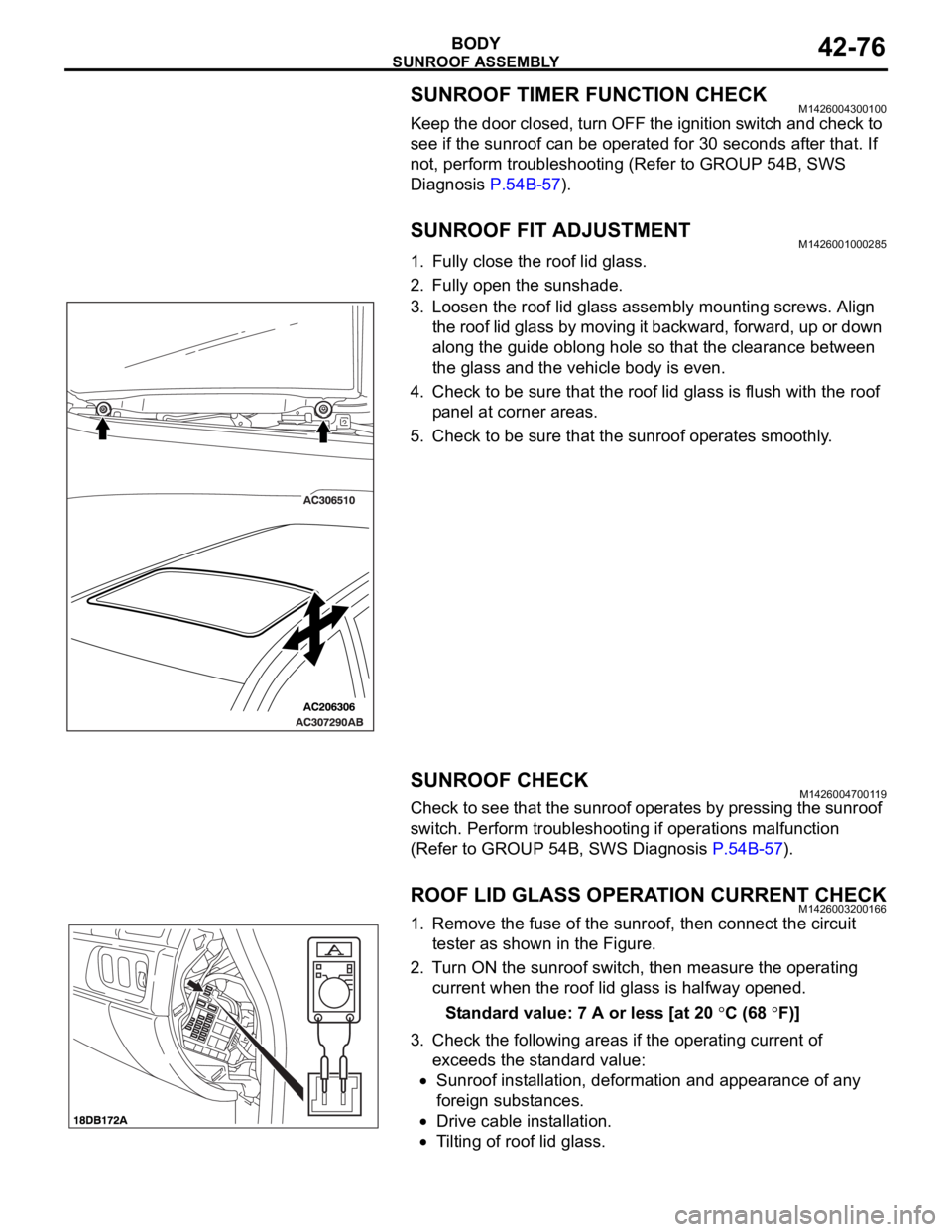
3. Loosen the roof lid glass assembly mounting screws. Align
the roof lid glass by moving it backward, forward, up or down
along the guide oblong hole so that the clearance between
the glass and the vehicle body is even.
4. Check to be sure that the roof lid glass is flush with the roof
panel at corner areas.
5. Check to be sure that the sunroof operates smoothly.
SUNROOF CHECKM1426004700119
Check to see that the sunroof operates by pressing the sunroof
switch. Perform troubleshooting if operations malfunction
(Refer to GROUP 54B, SWS Diagnosis P.54B-57).
ROOF LID GLASS OPERATION CURRENT CHECKM1426003200166
1. Remove the fuse of the sunroof, then connect the circuit
tester as shown in the Figure.
2. Turn ON the sunroof switch, then measure the operating
current when the roof lid glass is halfway opened.
Standard value: 7 A or less [at 20
C (68 F)]
3. Check the following areas if the operating current of
exceeds the standard value:
Sunroof installation, deformation and appearance of any
foreign substances.
Drive cable installation.
Tilting of roof lid glass.
Page 1145 of 1500
SUNROOF ASSEMBLY
BODY42-78
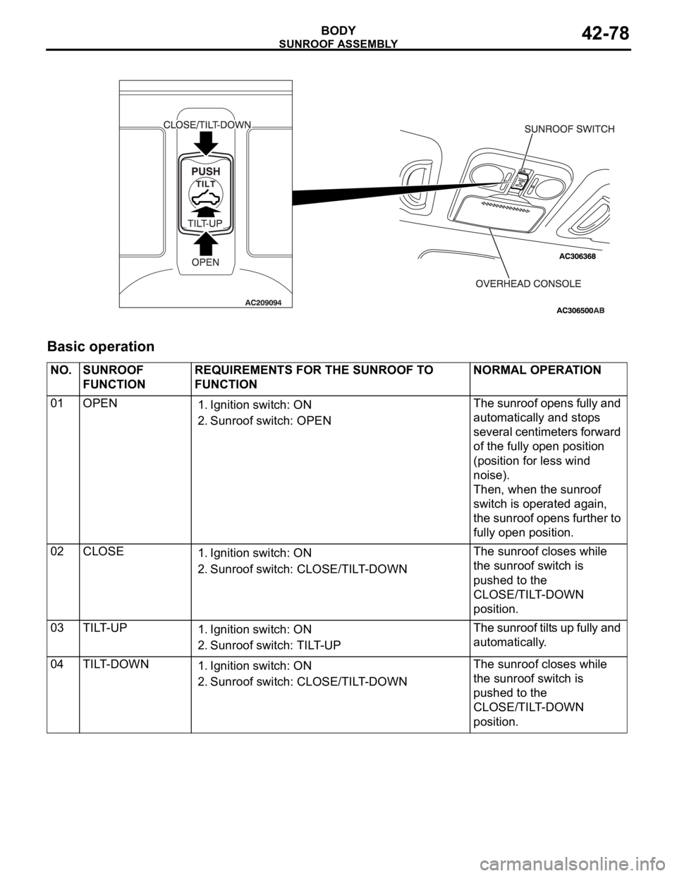
Basic operation
NO. SUNROOF
FUNCTIONREQUIREMENTS FOR THE SUNROOF TO
FUNCTIONNORMAL OPERATION
01 OPEN
1. Ignition switch: ON
2. Sunroof switch: OPENThe sunroof opens fully and
automatically and stops
several centimeters forward
of the fully open position
(position for less wind
noise).
Then, when the sunroof
switch is operated again,
the sunroof opens further to
fully open position.
02 CLOSE
1. Ignition switch: ON
2. Sunroof switch: CLOSE/TILT-DOWN The sunroof closes while
the sunroof switch is
pushed to the
CLOSE/TILT-DOWN
position.
03 TILT-UP
1. Ignition switch: ON
2. Sunroof switch: TILT-UPThe sunroof tilts up fully and
automatically.
04 TILT-DOWN
1. Ignition switch: ON
2. Sunroof switch: CLOSE/TILT-DOWNThe sunroof closes while
the sunroof switch is
pushed to the
CLOSE/TILT-DOWN
position.
Page 1146 of 1500

SUNROOF ASSEMBLY
BODY42-79
Sunroof timer mechanism
In cases except the following, the basic operation
and jam preventing mechanism will be maintained
for thirty seconds after the ignition switch is turned to
the LOCK (OFF) position. (Sunroof timer function)
If you open a door within that period (i.e. a door
switch is on), the sunroof timer function will be
cancelled immediately.
If you turn the ignition switch to the LOCK (OFF)
position while the timer is working, the sunroof
will continue moving until it closes fully, regard-
less of the time-out period. 05 AUTOMATIC
OPERATION
INTERRUPTION
(OPEN)A
1. Ignition switch: ON
2. Sunroof switch: OPEN or TILT-UPThe sunroof stops the
automatic opening
operation.
B
1. Ignition switch: ON
2. Sunroof switch: CLOSE/TILT DOWN (Push
the sunroof switch to the
CLOSE/TILT-DOWN position while the
sunroof is automatically opening and
release the switch within two seconds)The sunroof stops the
automatic opening
operation.
C
1. Ignition switch: ON
2. Sunroof switch: CLOSE/TILT DOWN (Push
the sunroof switch to the
CLOSE/TILT-DOWN position more than
two seconds while the sunroof is
automatically opening)The sunroof stops the
automatic opening
operation, and the sunroof
closes while the sunroof
switch is pushed to the
CLOSE/TILT-DOWN
position.
06 AUTOMATIC
OPERATION
INTERRUPTION
(TILT-UP)1. Ignition switch: ON
2. Sunroof switch: OPEN or TILT-UP, CLOSE/TILT
DOWNThe sunroof stops the
automatic opening
operation. NO. SUNROOF
FUNCTIONREQUIREMENTS FOR THE SUNROOF TO
FUNCTIONNORMAL OPERATION
Page 1179 of 1500
ON-VEHICLE SERVICE
BASIC BRAKE SYSTEM35A-14
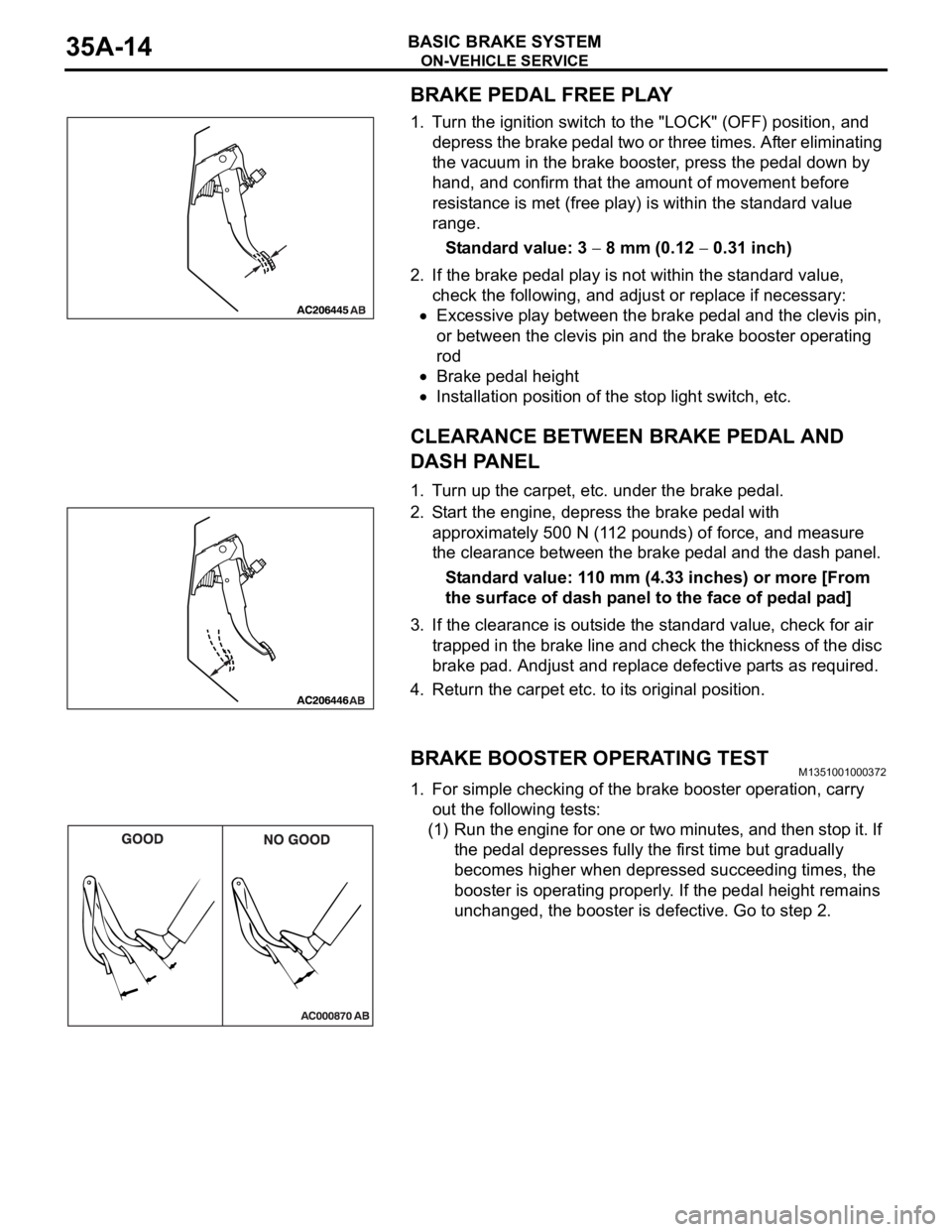
BRAKE PEDAL FREE PLAY
1. Turn the ignition switch to the "LOCK" (OFF) position, and
depress the brake pedal two or three times. After eliminating
the vacuum in the brake booster, press the pedal down by
hand, and confirm that the amount of movement before
resistance is met (free play) is within the standard value
range.
Standard value: 3
8 mm (0.12 0.31 inch)
2. If the brake pedal play is not within the standard value,
check the following, and adjust or replace if necessary:
Excessive play between the brake pedal and the clevis pin,
or between the clevis pin and the brake booster operating
rod
Brake pedal height
Installation position of the stop light switch, etc.
CLEARANCE BETWEEN BRAKE PEDAL AND
DASH PANEL
1. Turn up the carpet, etc. under the brake pedal.
2. Start the engine, depress the brake pedal with
approximately 500 N (112 pounds) of force, and measure
the clearance between the brake pedal and the dash panel.
Standard value: 110 mm (4.33 inches) or more [From
the surface of dash panel to the face of pedal pad]
3. If the clearance is outside the standard value, check for air
trapped in the brake line and check the thickness of the disc
brake pad. Andjust and replace defective parts as required.
4. Return the carpet etc. to its original position.
BRAKE BOOSTER OPERATING TESTM1351001000372
1. For simple checking of the brake booster operation, carry
out the following tests:
(1) Run the engine for one or two minutes, and then stop it. If
the pedal depresses fully the first time but gradually
becomes higher when depressed succeeding times, the
booster is operating properly. If the pedal height remains
unchanged, the booster is defective. Go to step 2.