engine MITSUBISHI ECLIPSE 1990 User Guide
[x] Cancel search | Manufacturer: MITSUBISHI, Model Year: 1990, Model line: ECLIPSE, Model: MITSUBISHI ECLIPSE 1990Pages: 391, PDF Size: 15.27 MB
Page 16 of 391
o-12GENERAL - Vehicle Identification
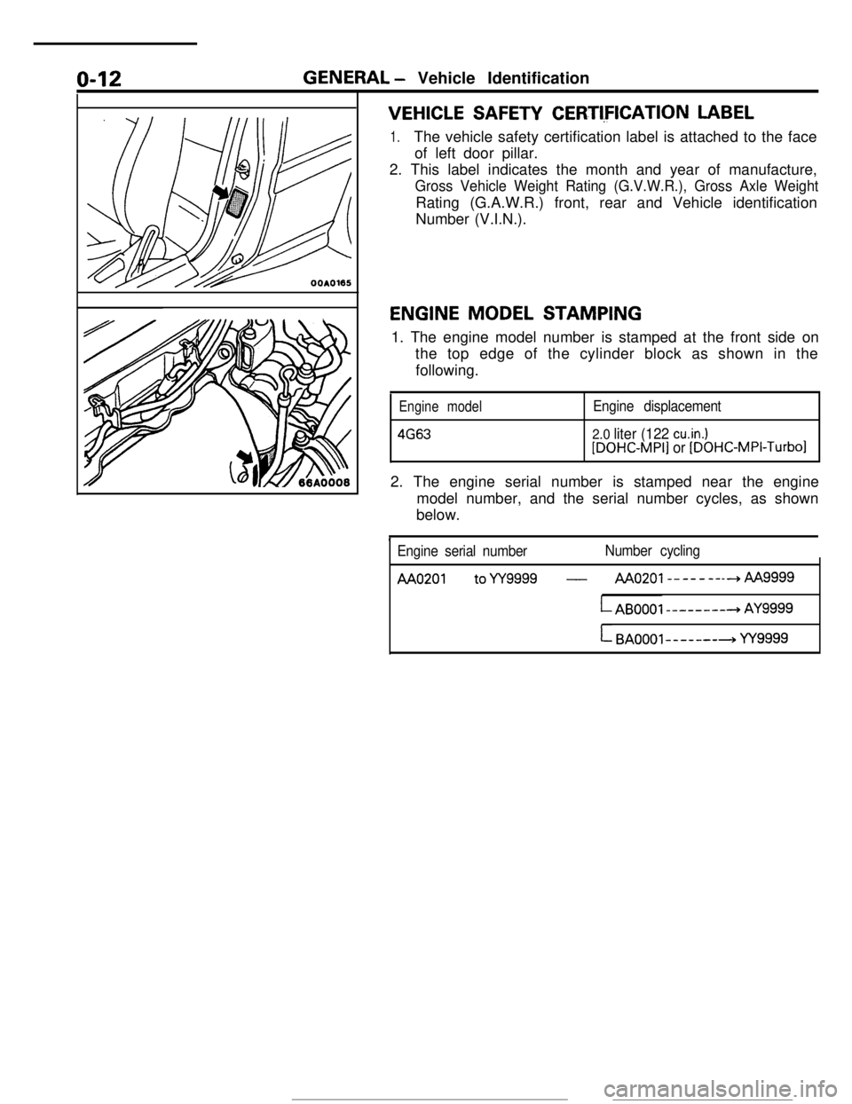
VEHICLE SAFETY CERTI,FICATION LABEL
1.The vehicle safety certification label is attached to the face
of left door pillar.
2. This label indicates the month and year of manufacture,
Gross Vehicle Weight Rating (G.V.W.R.), Gross Axle WeightRating (G.A.W.R.) front, rear and Vehicle identification
Number (V.I.N.).
ENGINE MODEL STAMPING
1. The engine model number is stamped at the front side on
the top edge of the cylinder block as shown in the
following.
Engine model
4663
Engine displacement
2.0 liter (122 cu.in.)[DOHC-MPI] or [DOHC-MPI-Turbo12. The engine serial number is stamped near the engine
model number, and the serial number cycles, as shown
below.
Engine serial numberNumber cycling
AA0201 toYY9999 -AAo201--------hAA
LAB0001 --------+ AY9999
L BAOOOl-------+ YY9999
Page 17 of 391
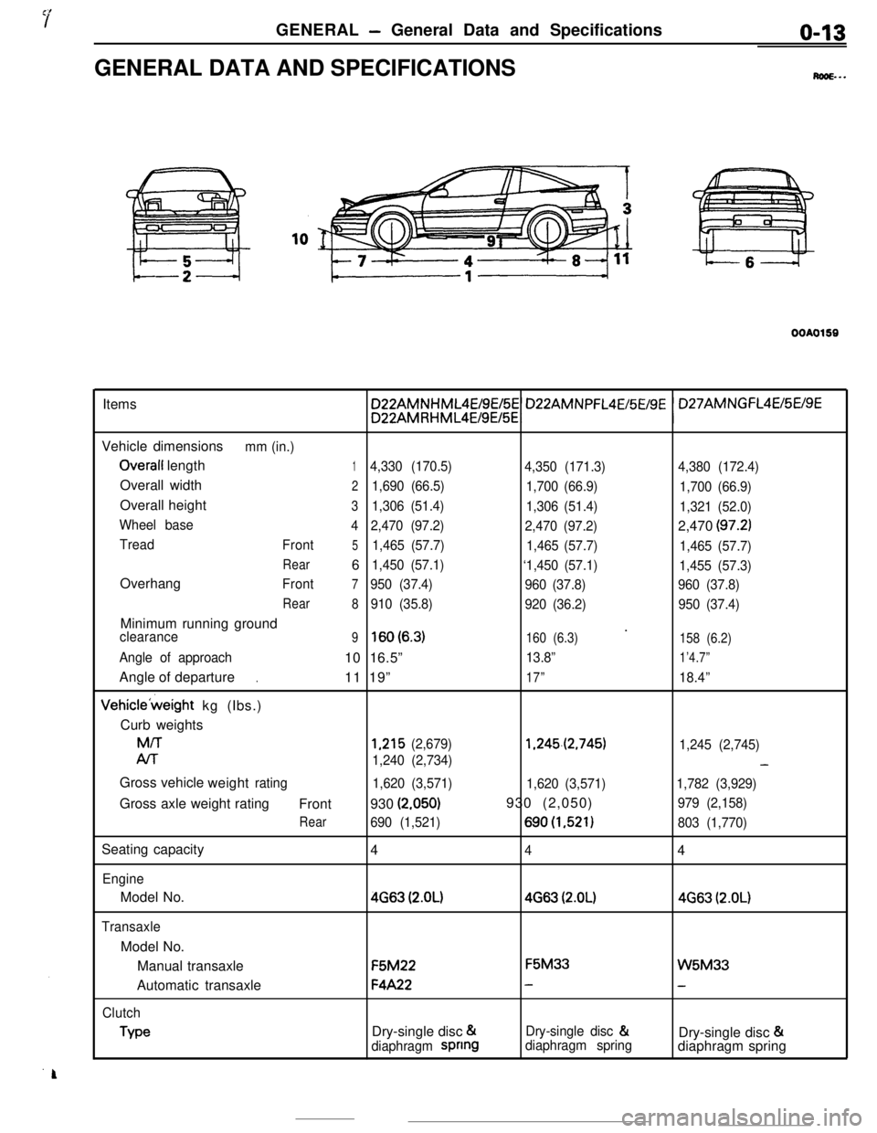
GENERAL - General Data and Specificationso-13GENERAL DATA AND SPECIFICATIONS
M...
OOAO159Items
Vehicle dimensions
mm (in.)
Overall length14,330 (170.5)
4,350 (171.3)4,380 (172.4)Overall width
21,690 (66.5)
1,700 (66.9)
1,700 (66.9)Overall height
31,306 (51.4)
1,306 (51.4)
1,321 (52.0)
Wheel base
42,470 (97.2)
2,470 (97.2)2,470
(97.2)
Tread
Front51,465 (57.7)
1,465 (57.7)
1,465 (57.7)
Rear61,450 (57.1)
‘1,450 (57.1)
1,455 (57.3)Overhang
Front7950 (37.4)
960 (37.8)960 (37.8)
Rear
8910 (35.8)
920 (36.2)950 (37.4)Minimum running ground
’clearance9lsO(6.3)160 (6.3)
158 (6.2)
Angle of approach10 16.5”13.8”1’4.7”Angle of departure
11 19”
17”18.4”.Vehicle’weight kg (Ibs.)
Curb weightsM/T
1,215 (2,679)1.245.(2,745)
1,245 (2,745)
Al-r
1,240 (2,734)-Gross vehicle
weight
rating
1,620 (3,571)
1,620 (3,571)1,782 (3,929)Gross axle weight rating
Front930
(2.050)930 (2,050)979 (2,158)
Rear690 (1,521)690(1,521)803 (1,770)Seating capacity
4
44
EngineModel No.
4663 (2.OL)4663 (2.OL)4663 (2.OL)
TransaxleModel No.
Manual transaxleF5M22F5M33
W5M33Automatic transaxle
F4A22--
Clutch
TypeDry-single disc &Dry-single disc &
Dry-single disc &
diaphragm spnngdiaphragm springdiaphragm spring
Page 18 of 391
o-14GENERAL - General Data and Specifications
tiems
Chassis
TireFront suspension
Type
Rear suspensionType
Brake
TypeFront
RearSteering
Gear type
Gear ratio
Fuel tankCapacity liters (gals.)
P205/55HR16 or
205l55VR 16Independent strut
3-Link
Torsion axleDisc
Disc
Rack and pinion
m
60 (16)
P205/55VR 16 or205155VR16Independent strut
3-Link
Torsion axleDisc
Disc
Rack and pinion
00
60 (16)
P205155VR16 or205155VR16Independent strut
Double wishbone
Disc
Disc
Rack and pinion
co
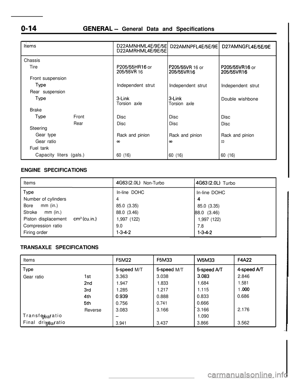
60 (16)ENGINE SPECIFICATIONS
Items
TypeNumber of cylinders
Boremm (in.)Stroke
mm (in.)Piston displacement
Compression ratio
Firing order
cm3 (cu.in.)
4G63 (2.OL) Non-Turbo1 4663 (2.OL) Turbo
In-line DOHC~ In-line DOHC
4‘4
85.0 (3.35)
85.0 (3.35)
88.0 (3.46)88.0 (3.46)
1,997 (122)
1,997 (122)
9.0
7.8l-3-4-2l-3-4-2
TRANSAXLE SPECIFICATIONS
Items
Type
Gear ratioTransfer ratio
gearFinal drive ratio
gear
1st
2nd
3rd4th5th
ReverseF5M22F5M33
W5M33F4A22
5-speed M/T5-speed M/T&speed ArF4-speed AiT
3.3633.038
3.0832.846
1.9471.8331.6841.581
1.2851.2171.1151 .ooo0.9390.8880.8330.686
0.756
0.7410.666
3.0833.166
’3.1662.176
-1.090
3.9413.4373.8663.562
Page 46 of 391
-. ..- ,..__ _. I-., . . . . -. . “-Ix.. ...~‘,.;;&;,-*~;
CLUTCH- Clutch Control6-3
-
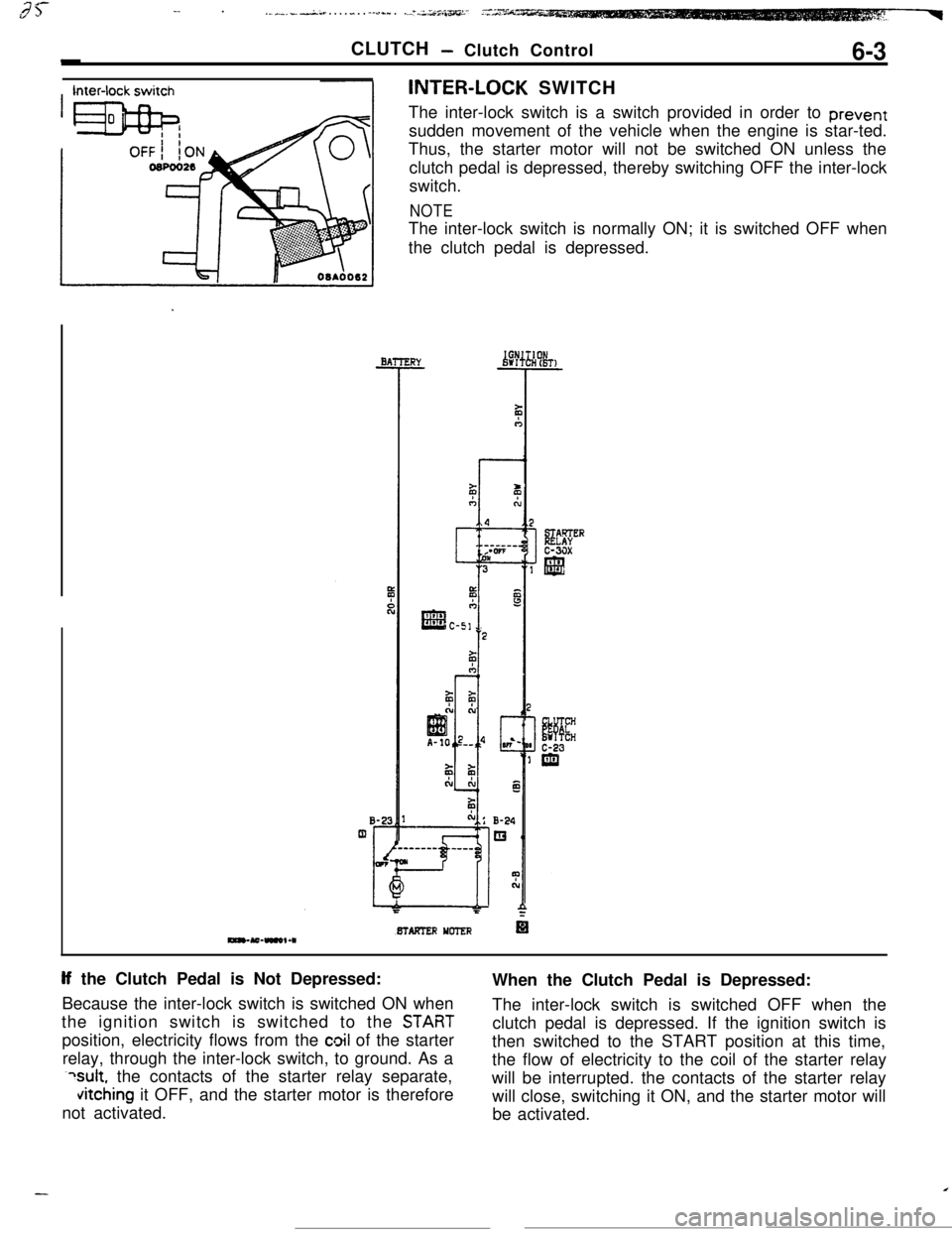
Inter-lock switchINTER-LOCK SWITCH
The inter-lock switch is a switch provided in order to prevent
sudden movement of the vehicle when the engine is star-ted.
BTAFTER YCTER
If the Clutch Pedal is Not Depressed:
Because the inter-lock switch is switched ON when
STABT
position, electricity flows from the cloil of the starter
relay, through the inter-lock switch, to ground. As a
?sult, the contacts of the starter relay separate,
vitching it OFF, and the starter motor is therefore
not activated.
Page 48 of 391
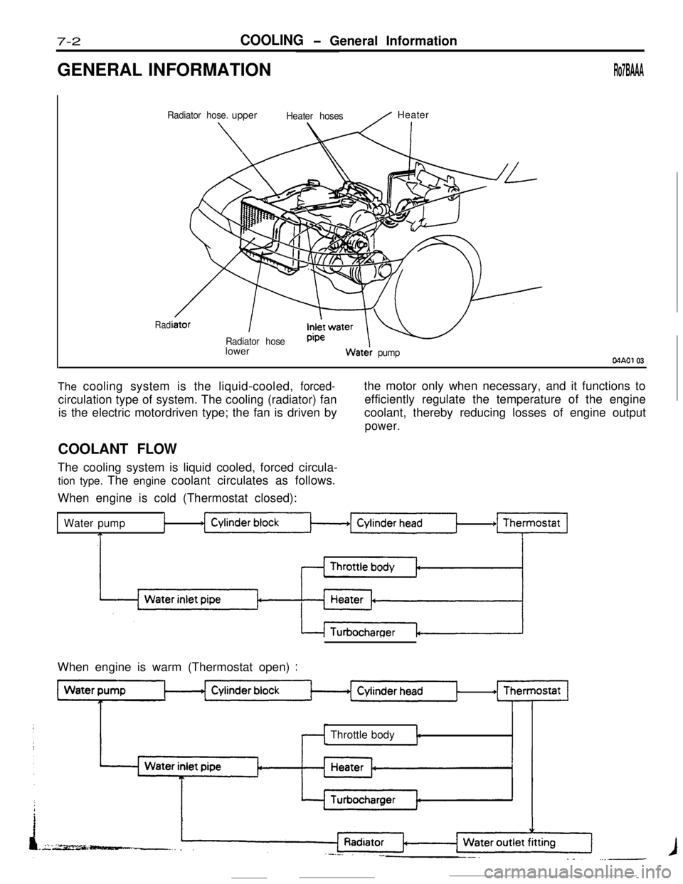
7-2 COOLIN G- General Information
/ Heater
Radi
Watei pumpMAO1 03
The cooling system is the liquid-cooled , forced-
1
T
+m
I
When engine is warm (Thermostat open) :
Throttle bodyt
Page 56 of 391
_--
8-4ELECTRICAL - Fuses / Diagnosis System
61543
2
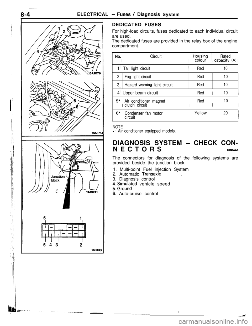
16R133lDEDICATED FUSES
For high-load circuits, fuses dedicated to each individual circuit
are used.
The dedicated fuses are provided in the relay box of the engine
compartment.
No.
I
Circuit
I
H,“d;;-;I
Rated
canacitv (A)I
1 1 Tail light circuitIRedI10I
2Fog light circuitRed10
3,.Hazard warning light circuitRed10
4 ) Upper beam circuitIRedI10I
5’
I
Air conditioner magnet
I
Red
I
10
clutch circuitI
6’Condenser fan motorYellow20
circuitI
NOTEl : Air conditioner equipped models.DIAGNOSIS SYSTEM
- CHECK CON-
NECTORS
nmcwaBThe connectors for diagnosis of the following systems are
provided beside the junction block.
1. Multi-point Fuel injection System
2. Automatic
Transaxle.3. Diagnosis control
z. grm.rlnaFd vehicle speed
6: Auto-cruise control
:..--.-__-.
Page 57 of 391
3i
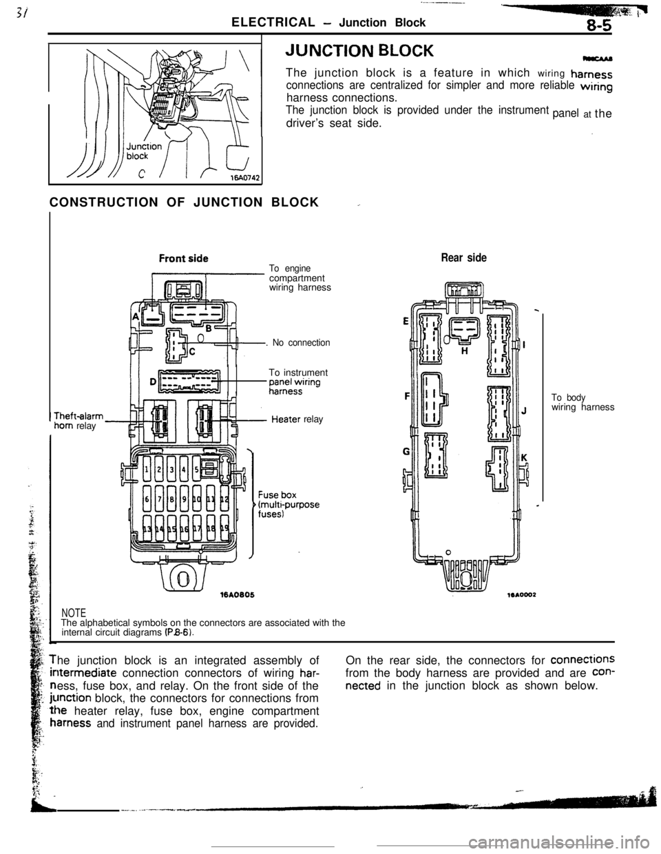
ELECTRICAL - Junction Block8-5JUNCTION
BLOCKThe junction block is a feature in which wiring
hamess
connections are centralized for simpler and more reliable wiringharness connections.
The junction block is provided under the instrumentdriver’s seat side.panelat the
CONSTRUCTION OF JUNCTION BLOCK
_.rheft-alarm
iom relay
To enginecompartment
wiring harness
. No connectionTo instrument
;;;+$ring
.’ ./%A0805relay
Rear side
NOTEThe alphabetical symbols on the connectors are associated with the
internal circuit diagrams
(PB-6).To bodywiring harness
he junction block is an integrated assembly ofltermediate connection connectors of wiring
har-ess, fuse box, and relay. On the front side of the
unction block, the connectors for connections from
le heater relay, fuse box, engine compartment
amess and instrument panel harness are provided.On the rear side, the connectors for connections
from the body harness are provided and are
con-
netted in the junction block as shown below.
Page 59 of 391
ELECTRICAL -Relavs, Control Units and Sensors
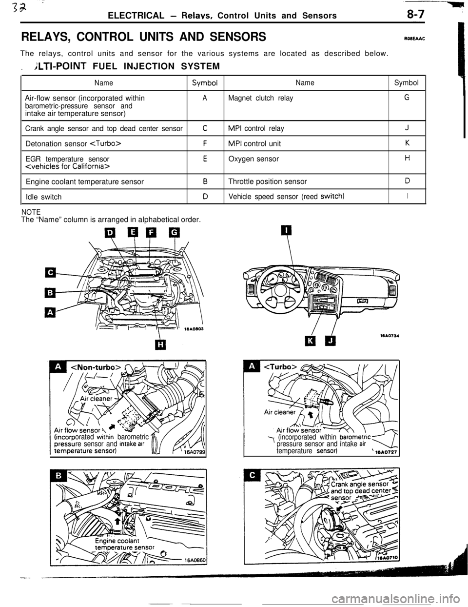
RELAYS, CONTROL UNITS AND SENSORSROBEAACThe relays, control units and sensor for the various systems are located as described below.
.ILTI-POINT FUEL INJECTION SYSTEM
NameSymbolNameSymbolAir-flow sensor (incorporated within
AMagnet clutch relayG
barometric-pressure sensor andintake air temperature sensor)
Crank angle sensor and top dead center sensorCMPI control relayJDetonation sensor
EGR temperature sensorEOxygen sensorH
Engine coolant temperature sensor
BThrottle position sensorDIdle switch
DVehicle speed sensor (reed switch)I
NOTEThe “Name” column is arranged in alphabetical order.
orated within barometric
re sensor and Intake arr7 (incorporated within barometnc kpressure sensor and intake arrtemperature sensor)-4L 1mo721
Page 63 of 391
1ELECTRICAL
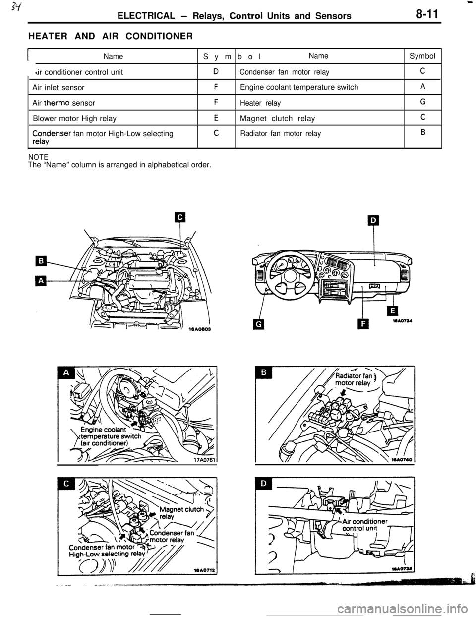
-Relays, Control Units and Sensors8-11HEATER AND AIR CONDITIONER
INameSymbolName
4ir conditioner control unitDCondenser fan motor relayAir inlet sensor
FEngine coolant temperature switch
Air therm0 sensor
FHeater relayBlower motor High relay
EMagnet clutch relay
$x$enser fan motor High-Low selectingCRadiator fan motor relay
NOTEThe “Name” column is arranged in alphabetical order.Symbol
C
A
G
C
B
Page 65 of 391
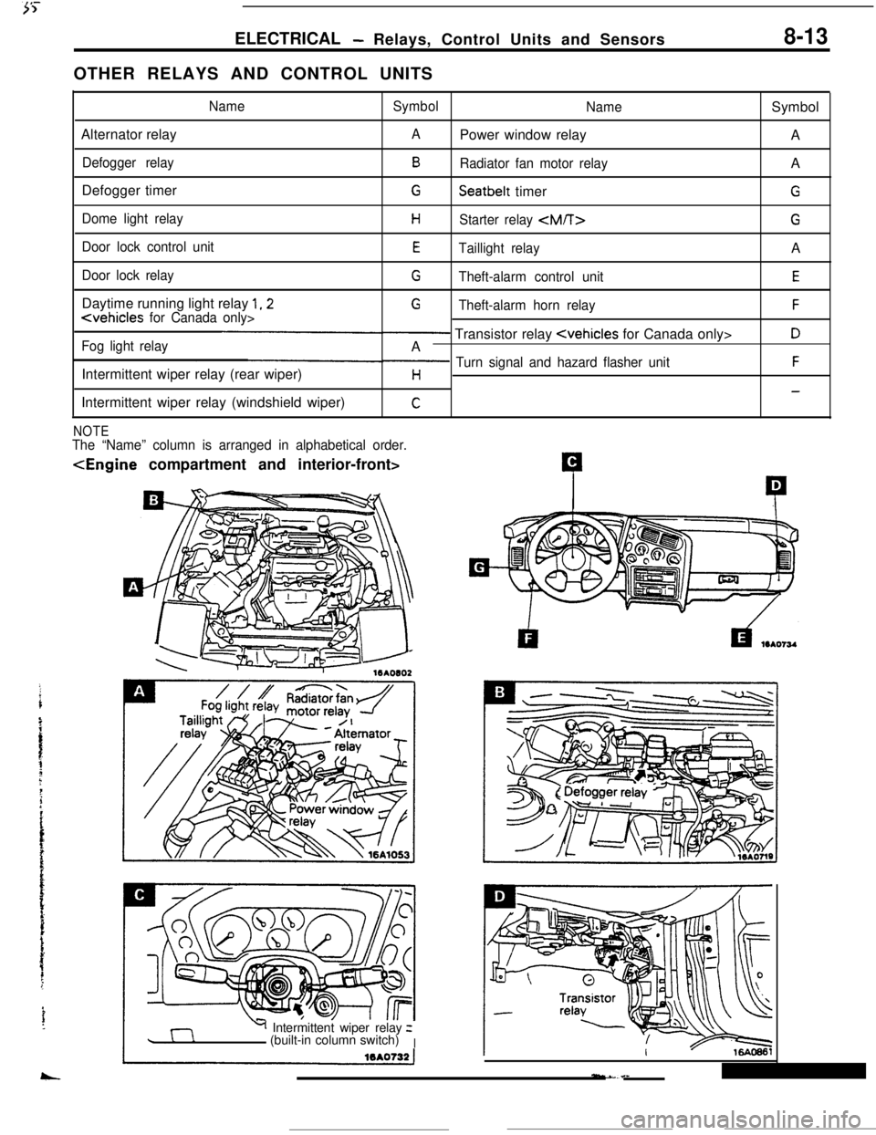
ELECTRICAL- Relays, Control Units and Sensors8-13OTHER RELAYS AND CONTROL UNITS
NameSymbol
NameSymbol
Alternator relay
APower window relay
A
Defogger relayBRadiator fan motor relayA
Defogger timer
GSeatbelt timerG
Dome light relayHStarter relay
Door lock control unitETaillight relayA
Door lock relayGTheft-alarm control unitEDaytime running light relay
1,2G
Fog light relay- Transistor relay
Intermittent wiper relay (rear wiper)
p Turn signal and hazard flasher unitFH-Intermittent wiper relay (windshield wiper)
C
NOTEThe “Name” column is arranged in alphabetical order.
Y Intermittent wiper relayz
(built-in column switch)
I