ESP MITSUBISHI ECLIPSE 1990 Owner's Manual
[x] Cancel search | Manufacturer: MITSUBISHI, Model Year: 1990, Model line: ECLIPSE, Model: MITSUBISHI ECLIPSE 1990Pages: 391, PDF Size: 15.27 MB
Page 159 of 391
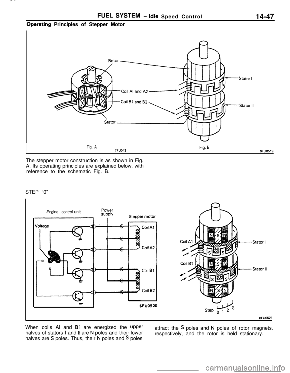
FUEL SYSTEM- Idle Speed Control14-47Operating Principles of Stepper Motor
Stator ICoil Al and
A2 e
Stator II
Fig. A7FUO43Fig. B6FUO519The stepper motor construction is as shown in Fig.
A. Its operating principles are explained below, with
reference to the schematic Fig.
8.STEP “0”
Engine controlunitPower
Coil B 1Coil
B2
I6FU0520
- Stator IStator
II
U
LdStep o 1 23When coils Al and
Bl are energized the upperhalves of stators I and
II are N poles and their lower
halves are
S poles. Thus, their N poles and S polesattract the
S poles and N poles of rotor magnets.
respectively, and the rotor is held stationary.
Page 161 of 391
FUEL SYSTEM -Idle Speed Control14-49
Servo ControlServo control includes feedback control and position
ontrol. In feedback control, the engine control uniti;onstantly calculates the actual idle speed, and if
the
value differs from the target idle speed, the unit
drives the stepper motor to adjust actual speed to
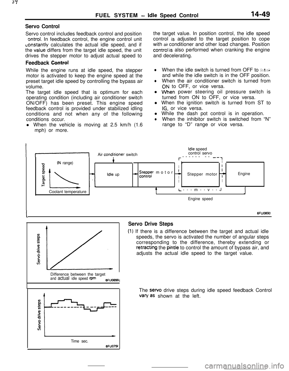
Feedback ControlWhile the engine runs at idle speed, the stepper
motor is activated to keep the engine speed at the
preset target idle speed by controlling the bypass air
volume.
The target idle speed that is optimum for each
operating condition (including air conditioner switch
ON/OFF) has been preset. This engine speed
feedback control is provided under stabilized idling
conditions and not when any of the following
conditions occur.
l When the vehicle is moving at 2.5 km/h (1.6
mph) or more.the target value. In position control, the idle speed
control
is adjusted to the target position to cope
with air conditioner and other load changes. Position
control is also performed when cranking the engine
and decelerating.
lWhen the idle switch is turned from OFF to ON,
and while the idle switch is in the OFF position.
lWhen the air conditioner switch is turned from
ON to OFF, or vice versa.
l When power steering oil pressure switch is
turned from ON to OFF, or vice versa.
l When the ignition switch is turned from ST to
IG, or vice versa.
l While the dash pot control is in operation.
lWhen the inhibitor switch is switched from “N”
range to “D” range or vice versa.
If-1Air conditioner switch
Idle speed
control servo
r------ -- -‘,
(N range)4* I-I
BI
8
IL -L
- !5ysr motor 1I
zIdle upIStepper motor 7Engine
PII2. I.1Coolant temperature
tL.---m--v--JJ
Engine speed
I6Fuo6oo
Servo Drive Steps
(1) If there is a difference between the target and actual idle
speeds, the servo is activated the number of angular steps
corresponding to the difference, thereby extending or
.retracting the pintle to control the amount of bypass air, and
adjusts the actual idle speed to the target value.
Difference between the target
and actual idle speed fpm6FUO699I
Time sec.
c
6FUO76!The sewo drive steps during idle speed feedback Control
van/ as shown at the left.
Page 163 of 391
FUEL SYSTEM -Idle Speed Control14-51
_ 0 (32)80 (175)Coolant temperature “C (“F)6FUO2653
ATarget position during operation
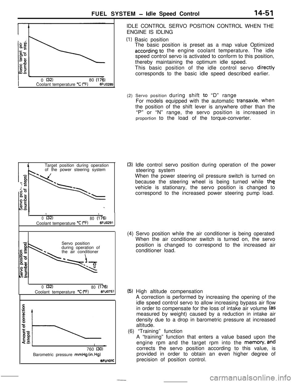
of the power steering systemIDLE CONTROL SERVO POSITION CONTROL WHEN THE
ENGINE IS IDLING
(1) Basic position
The basic position is preset as a map value Optimized
according to the engine coolant temperature. The idle
speed control servo is activated to conform to this position,
thereby maintaining the optimum idle speed.
This basic position of the idle control servo
diiectlycorresponds to the basic idle speed described earlier.
1II
0(32)
80(176)Coolant temperature
“C VW6FUO291Servo position
during operation of
the air conditioner
0(32)
80(176)Coolant temperature “C (“F)6FUO757
1L)760 (30)Barometric pressure mmHg
(in.Hg)BFUlOlC(2) Servo position during shift to “D” range
For models equipped with the automatic
transaxle.when
the position of the shift lever is anywhere other than the
“P” or “N” range, the servo position is increased in
proportion to the load of the torque-converter.
(3) Idle control servo position during operation of the power
steering system
When the power steering oil pressure switch is turned on
because the steering wheel is being turned while
thevehicle is stationary, the servo position is changed to
correspond to the increased power steering pump load.
(4) Servo position while the air conditioner is being operated
When the air conditioner switch is turned on, the servo
position is changed to correspond to the increased air
conditioner load.
(5) High altitude compensation
A correction is performed by increasing the opening of the
idle speed control servo to allow increasing bypass air flow
in order to compensate for the loss of intake air volume
(asmeasured by weight) caused by a reduction in intake air
density due to a drop in barometric pressure at increased
altitude.
(6) “Training” function
A “training” function that enters a value based upon the
engine rpm and the target rpm into the memon/,
andcorrects the servo position according to this value, is
provided in order to obtain an even higher degree of
precision of position control.
Page 164 of 391
--
14-52FUEL SYSTEM - Idle Speed Control
4
Start of deceleration
DLhq ON
position
I*2 to 6
Time sec.6FUO295
II)
0(32180(176)Temperature “C 1°F)6FUO29t
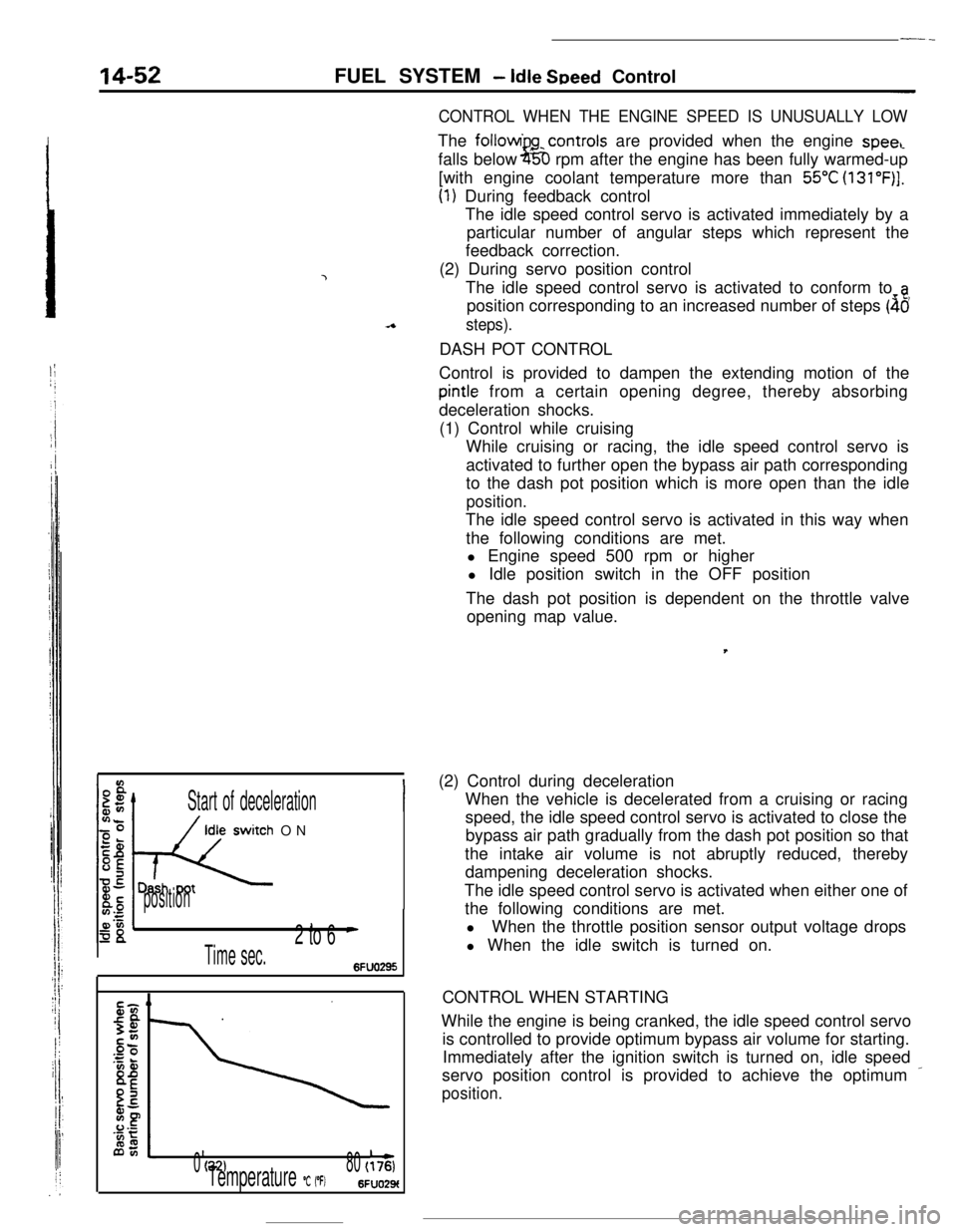
CONTROL WHEN THE ENGINE SPEED IS UNUSUALLY LOWThe followi
gcontrols are provided when the engine speecfalls below
i5;D rpm after the engine has been fully warmed-up
[with engine coolant temperature more than
55°C (131”F)].
(1) During feedback control
The idle speed control servo is activated immediately by a
particular number of angular steps which represent the
feedback correction.
(2) During servo position control
The idle speed control servo is activated to conform to
aposition corresponding to an increased number of steps
(46
steps).DASH POT CONTROL
Control is provided to dampen the extending motion of the
pintle from a certain opening degree, thereby absorbing
deceleration shocks.
(1) Control while cruising
While cruising or racing, the idle speed control servo is
activated to further open the bypass air path corresponding
to the dash pot position which is more open than the idle
position.The idle speed control servo is activated in this way when
the following conditions are met.
l Engine speed 500 rpm or higher
l Idle position switch in the OFF position
The dash pot position is dependent on the throttle valve
opening map value.,
(2) Control during deceleration
When the vehicle is decelerated from a cruising or racing
speed, the idle speed control servo is activated to close the
bypass air path gradually from the dash pot position so that
the intake air volume is not abruptly reduced, thereby
dampening deceleration shocks.
The idle speed control servo is activated when either one of
the following conditions are met.
lWhen the throttle position sensor output voltage drops
l When the idle switch is turned on.
CONTROL WHEN STARTING
While the engine is being cranked, the idle speed control servo
is controlled to provide optimum bypass air volume for starting.
Immediately after the ignition switch is turned on, idle speed
servo position control is provided to achieve the optimum
_
position.
Page 165 of 391
FUEL SYSTEM -Idle Speed Control I Power Supply Control14-53
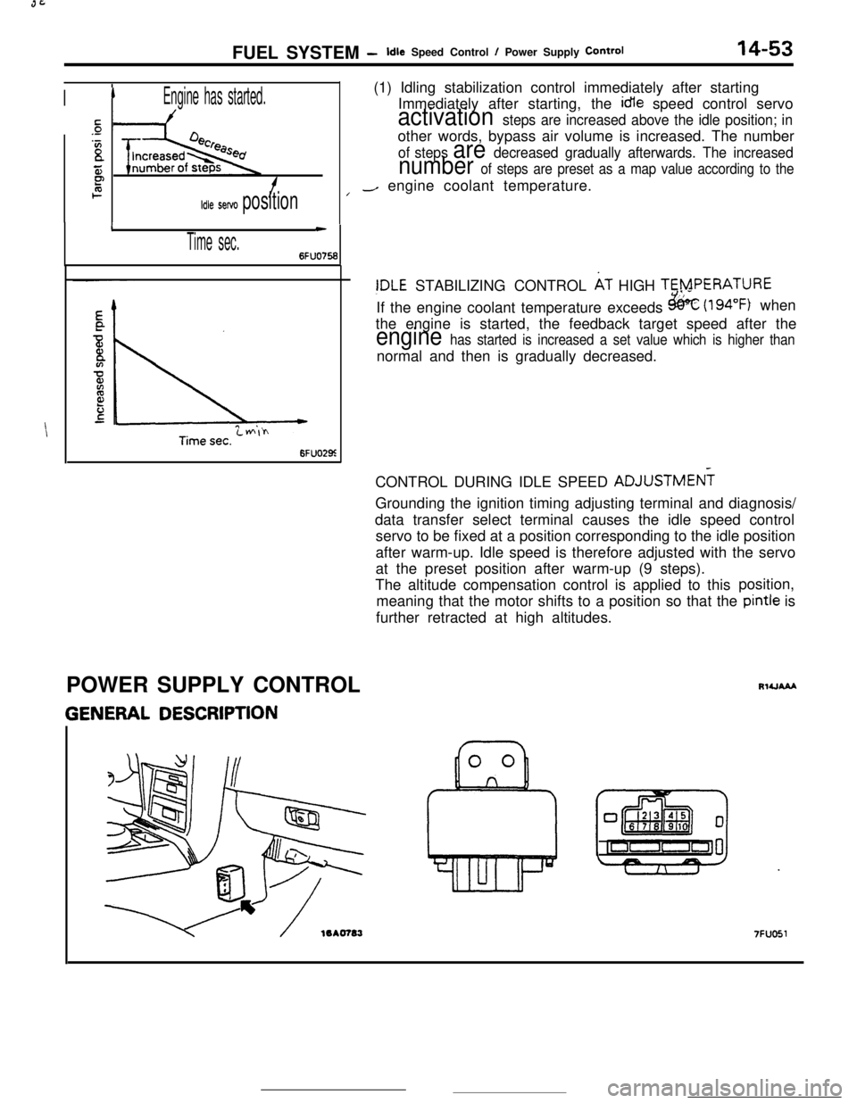
IIEngine has started.(1) Idling stabilization control immediately after starting
Immediately after starting, the idle speed control servo
sactivation steps are increased above the idle position; in.-
‘Bother words, bypass air volume is increased. The numberof steps are decreased gradually afterwards. The increased
55number of steps are preset as a map value according to theP2f/-/ engine coolant temperature.
Idle servo position
I
Time sec.
c
6FUO756
6FUO29z
!DLE STABILIZING CONTROL AT HIGH TERPERATURE
If the engine coolant temperature exceeds
&k (194°F) when
the engine is started, the feedback target speed after the
engine has started is increased a set value which is higher thannormal and then is gradually decreased.
CONTROL DURING IDLE SPEED ADJUSTMEN?
Grounding the ignition timing adjusting terminal and diagnosis/
data transfer select terminal causes the idle speed control
servo to be fixed at a position corresponding to the idle position
after warm-up. Idle speed is therefore adjusted with the servo
at the preset position after warm-up (9 steps).
The altitude compensation control is applied to thisposition,
meaning that the motor shifts to a position so that the pintle is
further retracted at high altitudes.
POWER SUPPLY CONTROL
GENERAL DESCRIPTION
RlUAAA
7FUO51
Page 174 of 391
14-62FUEL SYSTEM - Auto-cruise Control System
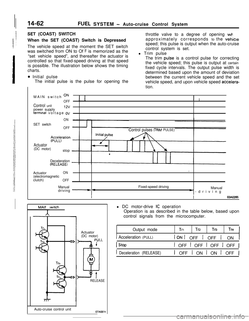
SET (COAST) SWITCH
When the SET (COAST) Switch is Depressed
The vehicle speed at the moment the SET switch
was switched from ON to Of
F is memorized as the
“set vehicle speed”,and thereafter the actuator is
controlled so that fixed-speed driving at that speed
is possible. The illustration below shows the timing
charts.
0 Initial pulse
The initial pulse is the pulse for opening thethrottle valve to a degree of opening
wk,approximately corresponds to the vehicle
speed; this pulse is output when the auto-cruise
control system is set.
l Trim pulse
The trim
pulse is a control pulse for correcting
the vehicle speed; this pulse is output at certain
fixed cycle intervals. The output pulse width is
determined based upon the amount of deviation
between the current vehicle speed and the set
vehicle speed, and upon vehicle speed
accelera-
tion.MAIN switch
ON
OFF! I
Control unitpower supply12vterminal voltage
ov
ON
SET switchOFF
$z;z$ration
Actuator(DC motor)stop
Control pulses (TRIMPULSE)Deceleration
(RELEASE)Actuator
ON(electromagnetic
clutch)
OFF
Manualdriving -*Fixed-speed driving,
Manual) -driving
II03440265
MAlt
A
Trtiwitch4
lr3Auto-cruise control unitActuator
(DC motor)
PULL
1
D
M
tRELEASE
Oi'AC01ll DC motor-drive
IC operation
Operation is as described in the table below, based upon
control signals from the microcomputer.
Output modeTnTrz TnTn
1 Acceleration (PULL)1 ON 1 OFF 1 OFF 1 ON1
1 OFF t OFF 1 OFF 1 OFF 1
1 Deceleration (RELEASE)1 OFF I ON I ON 1 OFF 1
Page 182 of 391
14-70
-_FUEL SYSTEM
- Auto-cruise Control System
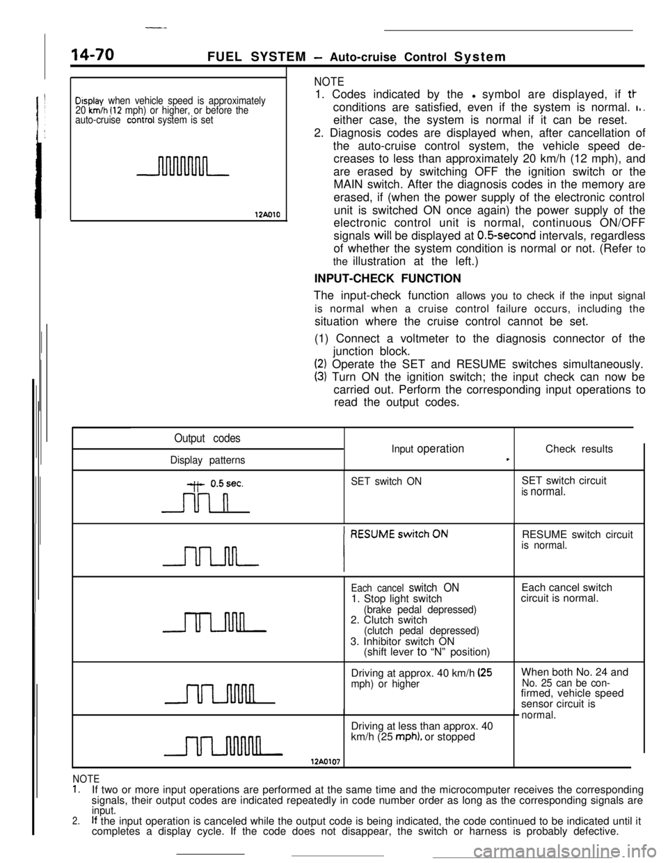
Display when vehicle speed is approximately
20 km/h (12 mph) or higher, or before the
auto-cruise conrrol system is set
12AolO
NOTE1. Codes indicated by thel symbol are displayed, if
tt-conditions are satisfied, even if the system is normal.
I,.either case, the system is normal if it can be reset.
2. Diagnosis codes are displayed when, after cancellation of
the auto-cruise control system, the vehicle speed de-
creases to less than approximately 20 km/h (12 mph), and
are erased by switching OFF the ignition switch or the
MAIN switch. After the diagnosis codes in the memory are
erased, if (when the power supply of the electronic control
unit is switched ON once again) the power supply of the
electronic control unit is normal, continuous ON/OFF
signals will be displayed at
O.&second intervals, regardless
of whether the system condition is normal or not. (Refer to
the illustration at the left.)
INPUT-CHECK FUNCTION
The input-check function allows you to check if the input signal
is normal when a cruise control failure occurs, including the
situation where the cruise control cannot be set.
(1) Connect a voltmeter to the diagnosis connector of the
junction block.
(2) Operate the SET and RESUME switches simultaneously.
(3) Turn ON the ignition switch; the input check can now be
carried out. Perform the corresponding input operations to
read the output codes.
Output codes
Display patternsInput
operationCheck resultst
y- 0.5sec.
n
SET switch ONSET switch circuitis normal.RESUME switch circuit
is normal.
Each cancel switch ON1. Stop light switch
(brake pedal depressed)2. Clutch switch
(clutch pedal depressed)3. Inhibitor switch ON
(shift lever to “N” position)Each cancel switch
circuit is normal.
Driving at approx. 40 km/h
(25mph) or higherWhen both No. 24 andNo. 25 can be con-firmed, vehicle speed
sensor circuit is
normal.Driving at less than approx. 40
km/h (25
mph). or stopped
NOTE1.If two or more input operations are performed at the same time and the microcomputer receives the corresponding
signals, their output codes are indicated repeatedly in code number order as long as the corresponding signals are
2.input.If the input operation is canceled while the output code is being indicated, the code continued to be indicated until it
completes a display cycle. If the code does not disappear, the switch or harness is probably defective.
Page 205 of 391
17-12REAR SUSPENSION - Double Wishbone Suspension
12AWY
lZAOOS!
When cornering. I.to the right
I Toe-inToe angle
ReboundBump-
PositiveCamber(to body)
- Camber to ground: 0
Bump
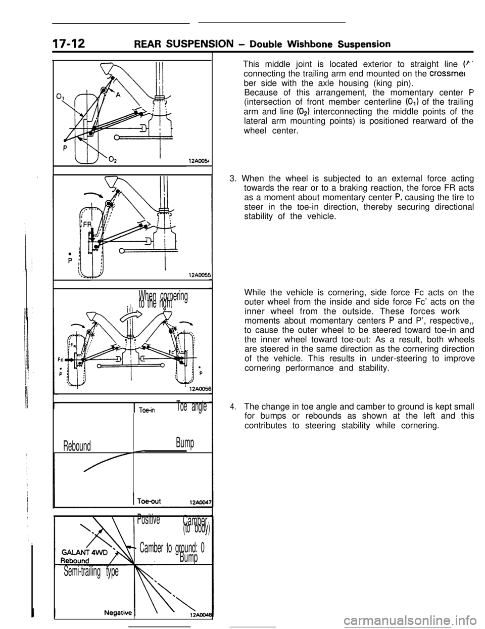
Semi-trailing typeThis middle joint is located exterior to straight line
(p’connecting the trailing arm end mounted on the crossmet
ber side with the axle housing (king pin).
Because of this arrangement, the momentary center
P(intersection of front member centerline
(0,) of the trailing
arm and line
(02) interconnecting the middle points of the
lateral arm mounting points) is positioned rearward of the
wheel center.
3. When the wheel is subjected to an external force acting
towards the rear or to a braking reaction, the force FR acts
as a moment about momentary center
P, causing the tire to
steer in the toe-in direction, thereby securing directional
stability of the vehicle.
While the vehicle is cornering, side force Fc acts on the
outer wheel from the inside and side force Fc’ acts on the
inner wheel from the outside. These forces work
moments about momentary centers
P and P’, respective,,
to cause the outer wheel to be steered toward toe-in and
the inner wheel toward toe-out: As a result, both wheels
are steered in the same direction as the cornering direction
of the vehicle. This results in under-steering to improve
cornering performance and stability.
4.The change in toe angle and camber to ground is kept small
for bumps or rebounds as shown at the left and this
contributes to steering stability while cornering.
Page 207 of 391
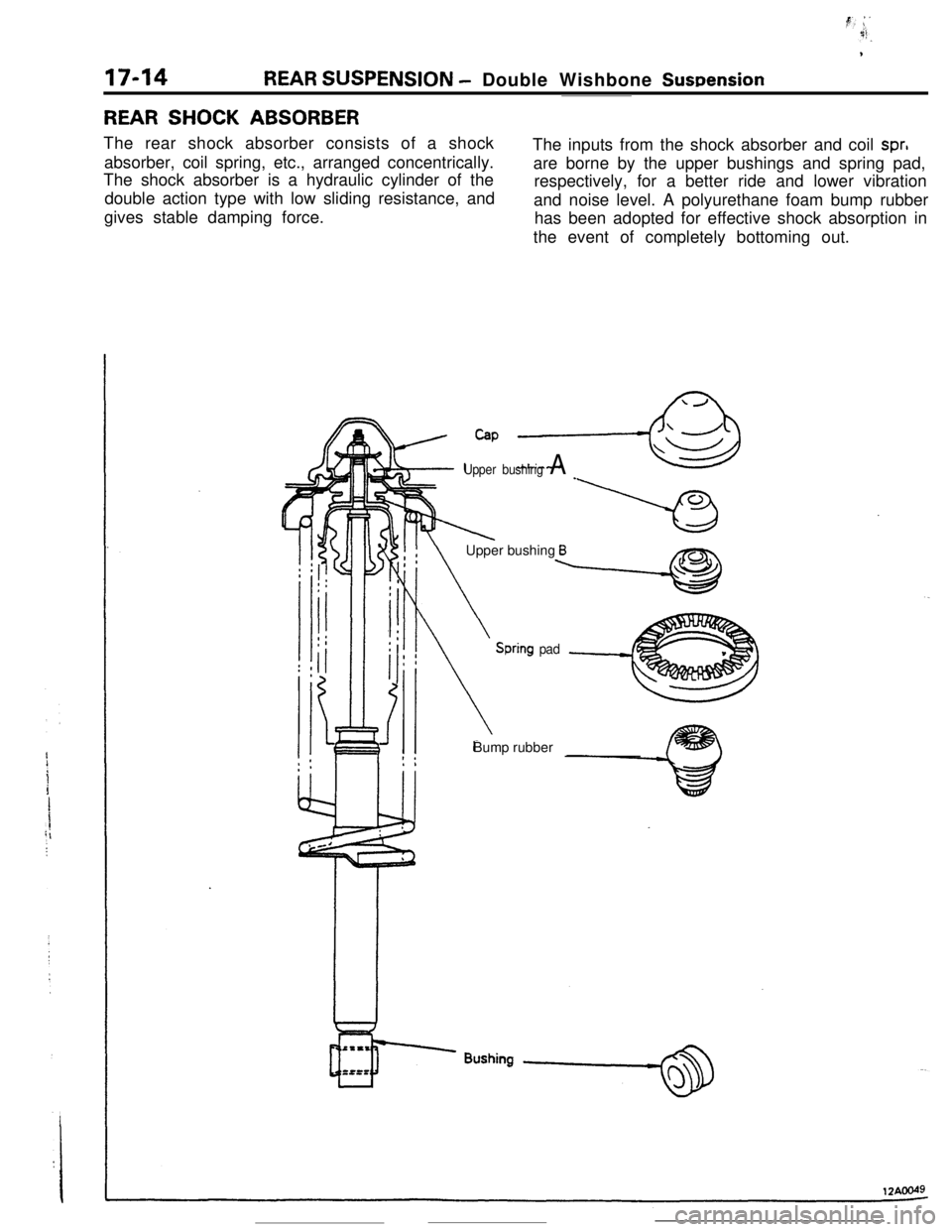
17-14REAR SUSPENSION - Double Wishbone Suwension
REAR SHOCK ABSORBERThe rear shock absorber consists of a shock
absorber, coil spring, etc., arranged concentrically.
The shock absorber is a hydraulic cylinder of the
double action type with low sliding resistance, and
gives stable damping force.The inputs from the shock absorber and coil
spr,are borne by the upper bushings and spring pad,
respectively, for a better ride and lower vibration
and noise level. A polyurethane foam bump rubber
has been adopted for effective shock absorption in
the event of completely bottoming out.
Cap ,-&
Upper bushing A _
IlXk!! \Upper bushing Bx?nb
Spring padBump rubber
Page 216 of 391
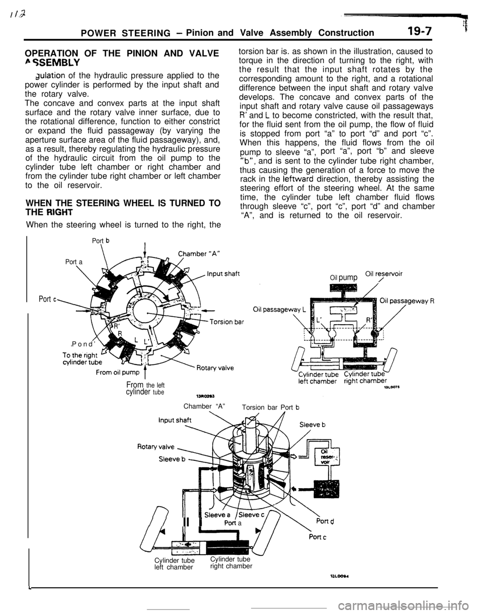
:POWER STEERING
- Pinion and Valve Assembly Construction19-7 ’fOPERATION OF THE PINION AND VALVE
fi %EMBLYdulation of the hydraulic pressure applied to the
power cylinder is performed by the input shaft and
the rotary valve.
The concave and convex parts at the input shaft
surface and the rotary valve inner surface, due to
the rotational difference, function to either constrict
or expand the fluid passageway (by varying the
aperture surface area of the fluid passageway), and,
as a result, thereby regulating the hydraulic pressure
of the hydraulic circuit from the oil pump to the
cylinder tube left chamber or right chamber and
from the cylinder tube right chamber or left chamber
to the oil reservoir.
WHEN THE STEERING WHEEL IS TURNED TOTHE
RIGHTWhen the steering wheel is turned to the right, the
Port b\
Port a\Pond’
Ltorsion bar is. as shown in the illustration, caused to
torque in the direction of turning to the right, with
the result that the input shaft rotates by the
corresponding amount to the right, and a rotational
difference between the input shaft and rotary valve
develops. The concave and convex parts of the
input shaft and rotary valve cause oil passageways
R’ and L to become constricted, with the result that,
for the fluid sent from the oil pump, the flow of fluid
is stopped from port “a” to port “d” and port “c”.
When this happens, the fluid flows from the oil
pump to sleeve “a”,port “a”, port “b” and sleeve
‘lb”, and is sent to the cylinder tube right chamber,
thus causing the generation of a force to move the
rack in the leftward direction, thereby assisting the
steering effort of the steering wheel. At the same
time, the cylinder tube left chamber fluid flows
through sleeve “c”, port “c”, port “d” and chamber
“A”, and is returned to the oil reservoir.
Port c
Oil pumpOil ryetvoir
From the leftcylinder tubeChamber “A”
Torsion bar Port
b
//II YPO< aPond
4Cylinder tube
left chamberCylinder tube
right chamber