ESP MITSUBISHI ECLIPSE 1990 Workshop Manual
[x] Cancel search | Manufacturer: MITSUBISHI, Model Year: 1990, Model line: ECLIPSE, Model: MITSUBISHI ECLIPSE 1990Pages: 391, PDF Size: 15.27 MB
Page 280 of 391
-
!-I
I!I
21-56AUTOMATIC TRANSAXLE - Transaxle Control~-REGULATOR VALVE
To torque convener
control valve
t
Toshift control valve,
pressure control valve
and N-D control valve(in “D”. ”2” or “L” range)
“D”.“2” or “L” range)
Oil filter
I1
To N-R control valve(in “R” range)Line relief valve
Oil pan
l
1750076
! To torque convener
IL‘I:control valve
Line pressure Pump
Li Ae(from oil pump) suctionprest$$)7,This
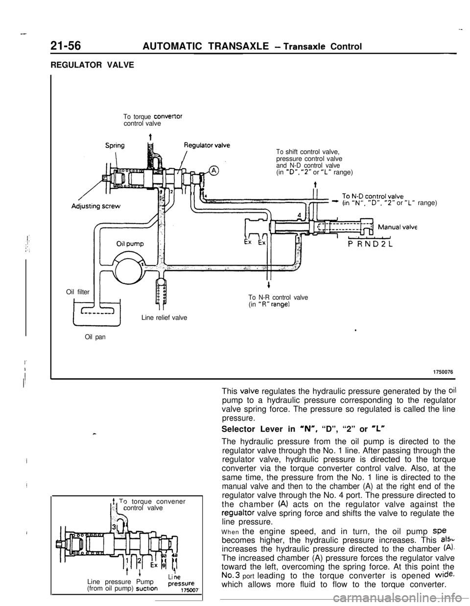
valve regulates the hydraulic pressure generated by the oilpump to a hydraulic pressure corresponding to the regulator
valve spring force. The pressure so regulated is called the line
pressure.Selector Lever in
‘N”, “D”, “2” or “L”The hydraulic pressure from the oil pump is directed to the
regulator valve through the No. 1 line. After passing through the
regulator valve, hydraulic pressure is directed to the torque
converter via the torque converter control valve. Also, at the
same time, the pressure from the No. 1 line is directed to the
manual valve and then to the chamber (A) at the right end of theregulator valve through the No. 4 port. The pressure directed to
the chamber
(A) acts on the regulator valve against theregualtor valve spring force and shifts the valve to regulate the
line pressure.
When the engine speed, and in turn, the oil pump spe
becomes higher, the hydraulic pressure increases. This
aI%increases the hydraulic pressure directed to the chamber
(A).The increased chamber (A) pressure forces the regulator valve
toward the left, overcoming the spring force. At this point theNo.3 port leading to the torque converter is opened
wide+which allows more fluid to flow to the torque converter.
Page 284 of 391
21-60AUTOMATIC TRANSAXLE - Transaxle Control
REDUCING VALVE
Reducing valve
ExLine
press1
ExAdjusting
‘screw
N-R control valveunit
J&Pressure
+controlsblenoid valve.1750082
Line
’To pressure controlpressure solenoid valve
Line
’To pressure controlpressure
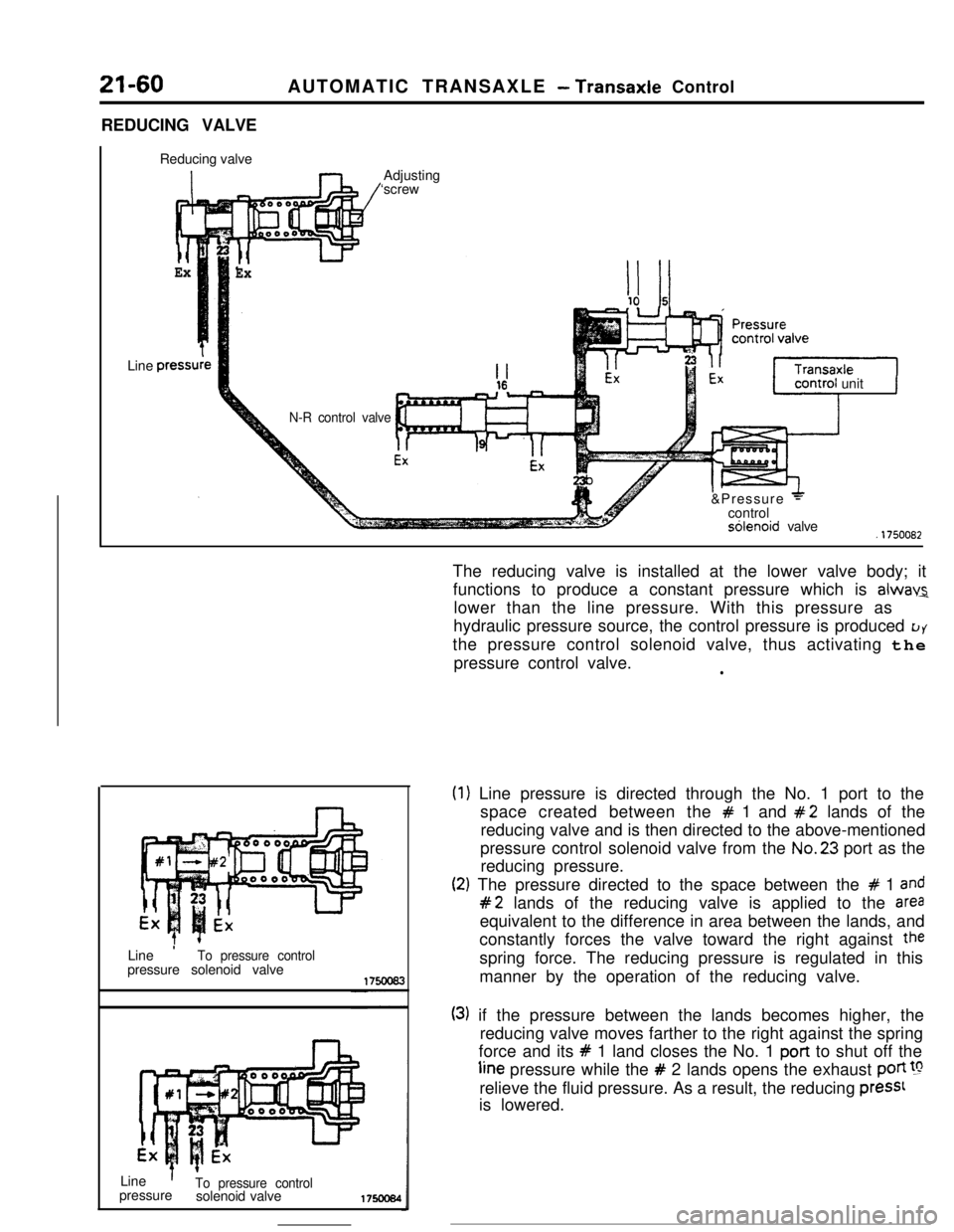
solenoid valve175ocs4The reducing valve is installed at the lower valve body; it
functions to produce a constant pressure which is
alwav2lower than the line pressure. With this pressure as
hydraulic pressure source, the control pressure is produced
LJYthe pressure control solenoid valve, thus activating the
pressure control valve.
l
(1
(2
) Line pressure is directed through the No. 1 port to the
space created between the
# 1 and #2 lands of the
reducing valve and is then directed to the above-mentioned
pressure control solenoid valve from the No.23 port as the
reducing pressure.
:) The pressure directed to the space between the # 1 and
#2 lands of the reducing valve is applied to the areaequivalent to the difference in area between the lands, and
constantly forces the valve toward the right against
thespring force. The reducing pressure is regulated in this
manner by the operation of the reducing valve.
(3) if the pressure between the lands becomes higher, the
reducing valve moves farther to the right against the spring
force and its
# 1 land closes the No. 1 port to shut off theline pressure while the
# 2 lands opens the exhaust poti !grelieve the fluid pressure. As a result, the reducing
press1is lowered.
Page 291 of 391
/gi--__ .--.-9
Reducingvalve
To kickdown
servo via 1 - 2
shift valveLine pressureAUTOMATIC TRANSAXLE
- Transaxle Control21-69
PRESSURE CONTROL VALVE, SOLENOID
-_ VALVE AND N-R CONTROL VALVE
: Pressure Control Valve
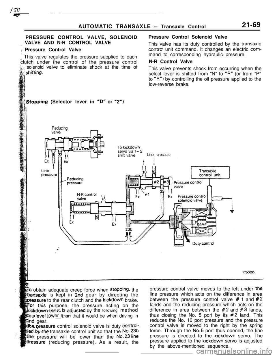
: This valve regulates the pressure supplied to each
clutch under the control of the pressure control
j.. solenoid<,A ,valve to eliminate shock at the time ofPressure Control Solenoid Valve
This valve has its duty controlled by the transaxlecontrol unit command. It changes an electric com-
mand to corresponding hydraulic pressure.
N-R Control Valve
This valve prevents shock from occurring when the
select lever is shifted from “N” to
“R” (or from “P”
to
“R”) by controlling the oil pressure applied to the
low-reverse brake..Stopping (Selector lever in
“D” or “2”)
‘r) obtain adequate creep force when stopping, the
is kept in
2nd gear by directing the
to the rear clutch and the kickdown brake.
purpose, the pressure acting on the
=nnm is adjusted by the following method
- .--v.._ _ _ __ --Tan that it would be when driving in
..d gear.
he nrennurecontrol solenoid valve is duty control-
..s,. ..Jtransaxle control unit so that the No.231..a
pressure will be lower than the No.23
fine
bressure (reducing pressure). As a result, the
level lower ttlpressure control valve moves to the left under the
line pressure which acts on the difference in area
between the pressure control valve
# 1 and #2lands and the reducing pressure which acts on the
difference in area between the
#2 and #3 lands,
thus closing the No. 5 port by its
#2 land. This
reduces the No. 10 port pressure and the pressure
control valve is moved to the right by the spring
force. Through the No.5 port thus opened, the line
pressure is directed to the kickdown servo. The
pressure applied to the kickdown servo is adjusted
by the above-mentioned sequence.
-
Page 295 of 391
AUTOMATIC TRANSAXLE - Transaxle Control21-73
‘elector Lever in “R”
Reducingvalve
ReducingTo low-reverse
OFF1750099
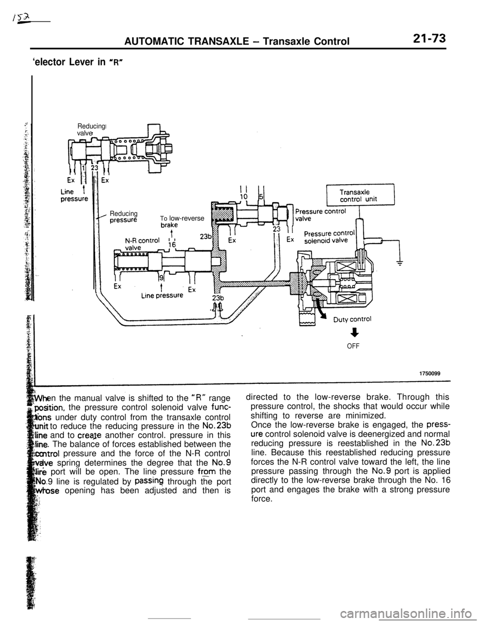
en the manual valve is shifted to the
“R” rangedirected to the low-reverse brake. Through this
ition, the pressure control solenoid valve func-pressure control, the shocks that would occur while
Ions under duty control from the transaxle controlshifting to reverse are minimized.
to reduce the reducing pressure in the No.23bOnce the low-reverse brake is engaged, the press-and to creaje another control. pressure in this
ure control solenoid valve is deenergized and normal
. The balance of forces established between thereducing pressure is reestablished in the No.23bntrol pressure and the force of the N-R controlline. Because this reestablished reducing pressure
Ivespring determines the degree that the No.9forces the N-R control valve toward the left, the line
e port will be open. The line pressure from thepressure passing through the No.9 port is applied
9 line is regulated by
passinq through the portdirectly to the low-reverse brake through the No. 16
ose opening has been adjusted and then isport and engages the brake with a strong pressure
force.
Page 298 of 391
?
I
21-76AUTOMATIC TRANSAXLE - Transaxle Control
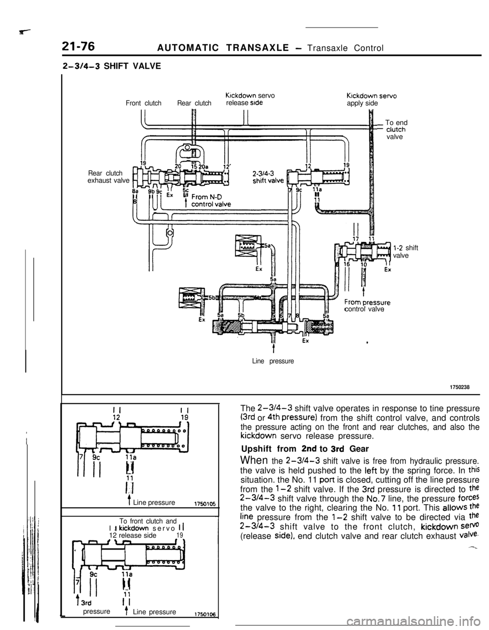
2-314-3 SHIFT VALVE
Rear clutchexhaust valve
Front clutchRear clutchKlckdown servo
release stdeKickdown servo
apply side
?I
l-2 shift
valve
control valve
_ To end- ciutch
valvet
Line pressure
1750238
II
i Line pressure1750105
To front clutch andI 1 kickdown servo 1 112 release side19n fln
IIT3rd
pressure
t- Line pressureThe
2-WI-3 shift valve operates in response to tine pressure
(3rd or 4th pressure) from the shift control valve, and controls
the pressure acting on the front and rear clutches, and also thekickdown servo release pressure.
Upshift from
2nd to 3rd Gear
When the 2-3/4-3 shift valve is free from hydraulic pressure.the valve is held pushed to the left by the spring force. In
thissituation. the No. 11 pan is closed, cutting off the line pressure
from the
1-2 shift valve. If the 3rd pressure is directed to the
2-3/4-3 shift valve through the No.7 line, the pressure forcesthe valve to the right, clearing the No.
11 port. This allows the
fine pressure from the l-2 shift valve to be directed via the
2-3/4-3 shift valve to the front clutch, kickdown sem(release
side), end clutch valve and rear clutch exhaust valve.
Page 381 of 391
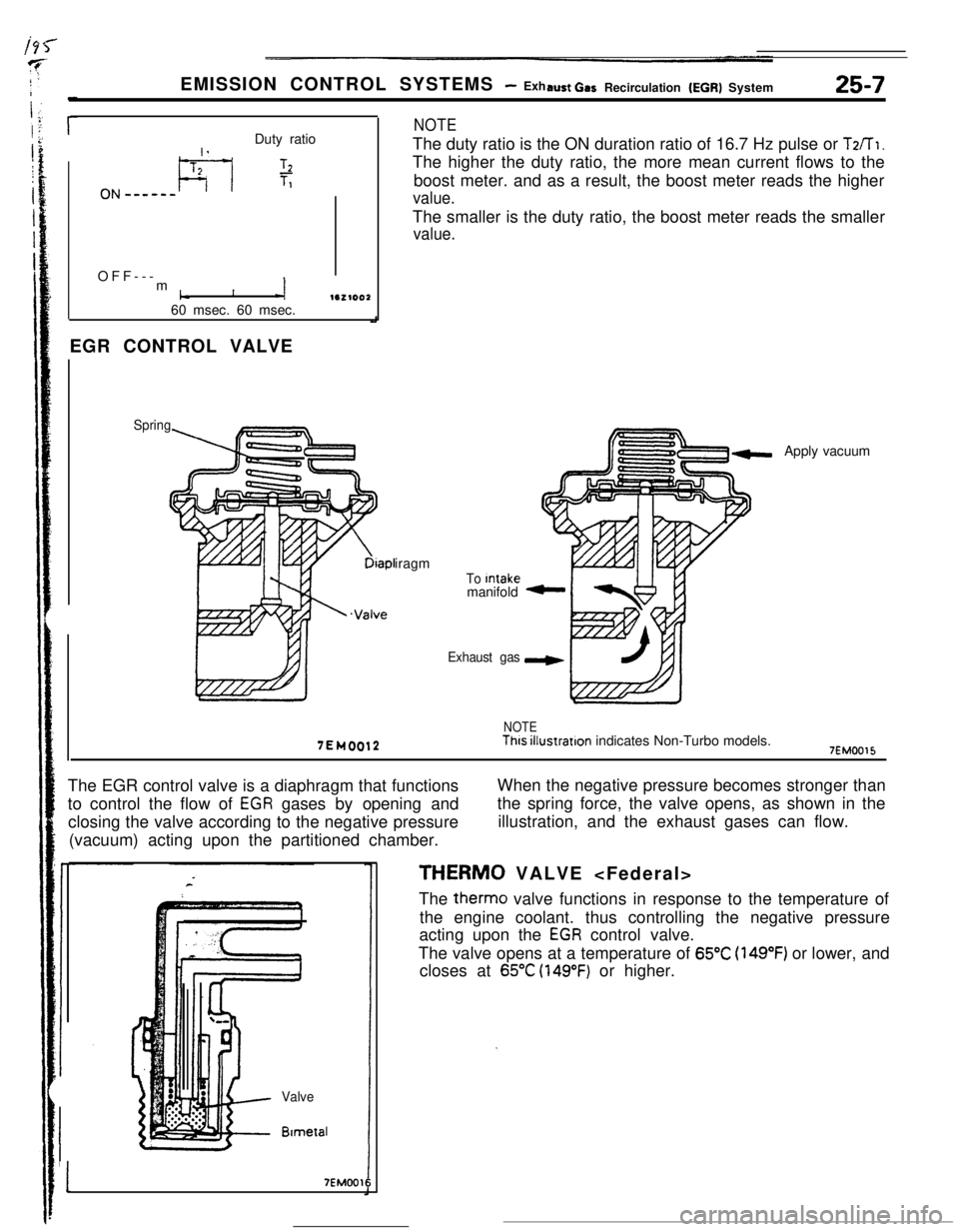
EMISSION CONTROL SYSTEMS - Exhaust Car Recirculation (EGR) System25-7Duty ratio
I .,
ON e-_-m-L--l
T2L1.TlOFF---
m
1c1-i1e2100260 msec. 60 msec.
EGR CONTROL VALVE
Spring
NOTEThe duty ratio is the ON duration ratio of 16.7 Hz pulse or
T2/T1.The higher the duty ratio, the more mean current flows to the
boost meter. and as a result, the boost meter reads the higher
value.The smaller is the duty ratio, the boost meter reads the smaller
value.
Diapl
.Valveiragm
To Intakemanifold
Exhaust gasApply vacuum
7EM0012
NOTEThis illustration indicates Non-Turbo models.7EMOO15The EGR control valve is a diaphragm that functions
to control the flow of
EGR gases by opening and
closing the valve according to the negative pressure
(vacuum) acting upon the partitioned chamber.When the negative pressure becomes stronger than
the spring force, the valve opens, as shown in the
illustration, and the exhaust gases can flow.
Valve
BlmetzII
17EMOO16
THERM0 VALVE
The therm0 valve functions in response to the temperature of
the engine coolant. thus controlling the negative pressure
acting upon the
EGR control valve.
The valve opens at a temperature of
65°C (149°F) or lower, and
closes at
65°C (149°F) or higher.
Page 384 of 391
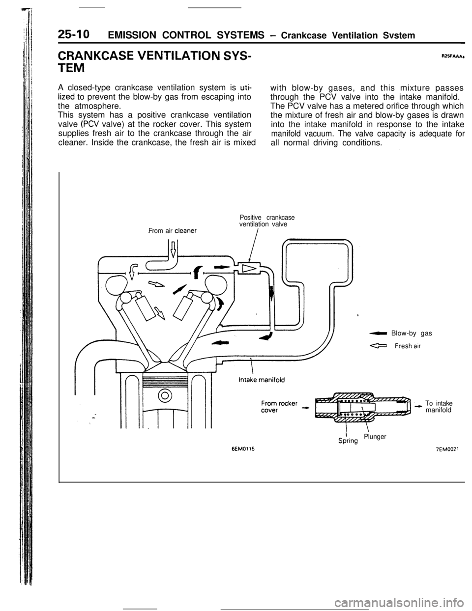
25-10EMISSION CONTROL SYSTEMS - Crankcase Ventilation Svstem-
CRANKCASE VENTILATION SYS-fUSFAAA,r
TEMA closed-type crankcase ventilation system is
uti-with blow-by gases, and this mixture passes
lized to prevent the blow-by gas from escaping into
through the PCV valve into the intake manifold.
the atmosphere.The PCV valve has a metered orifice through which
This system has a positive crankcase ventilation
the mixture of fresh air and blow-by gases is drawn
valve
(PCV valve) at the rocker cover. This system
into the intake manifold in response to the intake
supplies fresh air to the crankcase through the air
manifold vacuum. The valve capacity is adequate forcleaner. Inside the crankcase, the fresh air is mixed
all normal driving conditions.
From air cleanerPositive crankcaseventilation valve
a Blow-by gas
a Freshair
To intakemanifold
6EM0115
SiringPlunger
7EMOOZi