ESP MITSUBISHI ECLIPSE 1990 User Guide
[x] Cancel search | Manufacturer: MITSUBISHI, Model Year: 1990, Model line: ECLIPSE, Model: MITSUBISHI ECLIPSE 1990Pages: 391, PDF Size: 15.27 MB
Page 124 of 391

140’I2FUEL SYSTEM- Intake Air Control
INTAKE AIR CONTROL
GENERAL DESCRIPTION
Rl4oA?, Speed adjusting screwIdle oositionswitch-
Throttle valve
0
+ Bypass air flow
before metenng
Q Bypass air fjow
Iafter metenng
Idle soeed control servo
-?hrottle position sensor
Fast idle air valve
oolant from thermostat case
ITo return pipe6FUO777Control of the volume of intake air is performed by the throttle
valve, the speed adjusting screw, the fast idle air valve and the
idle speed control servo, all of which are mounted on
ttithrottle body.
iControl by idle
w/d c;zk;;fast
hhidle air valve
Speed adjusting screwThrottle valve
m-30~22) of321 sofm 6of140~ 901164
Coolant temperature ‘C (OF)6Fuo!DURING ENGINE WARM UP
The intake air flow during fast idle is controlled by both the wax
actuated air valve which functions. in response to the engine
coolant temperature and the idle speed control servo that is
controlled by the engine control unit.
AFTER ENGINE HAS BEEN WARMED UP
Control of the intake air flow during curb idle (or the control of
curb idle speed) is performed by the idle speed control servo
which in turn is controlled by the engine control unit.
Refer to page 1445 for control of the idle speed control servo.The idle speed can be adjusted. by increasing or decreasing theintake air flow rate with the speed adjusting screw.
The off-idle intake air flow is controlled by the throttle
valve;operation of the accelerator pedal determines the degree that
the throttle valve is open at any particular moment.
-
.?‘h,
. .
Page 125 of 391
FUEL SYSTEM- Intake Air Control
SPECIFICATIONS
ternsThrottle body
Throttle bore diametermm
(in.1Fast idle air valve
TwValve closing temperature
“C (“F)
Idle speed control servo
TypeSpecifications
60 (2.362)
WAX type
Approximately 50
(122)Stepper motor type
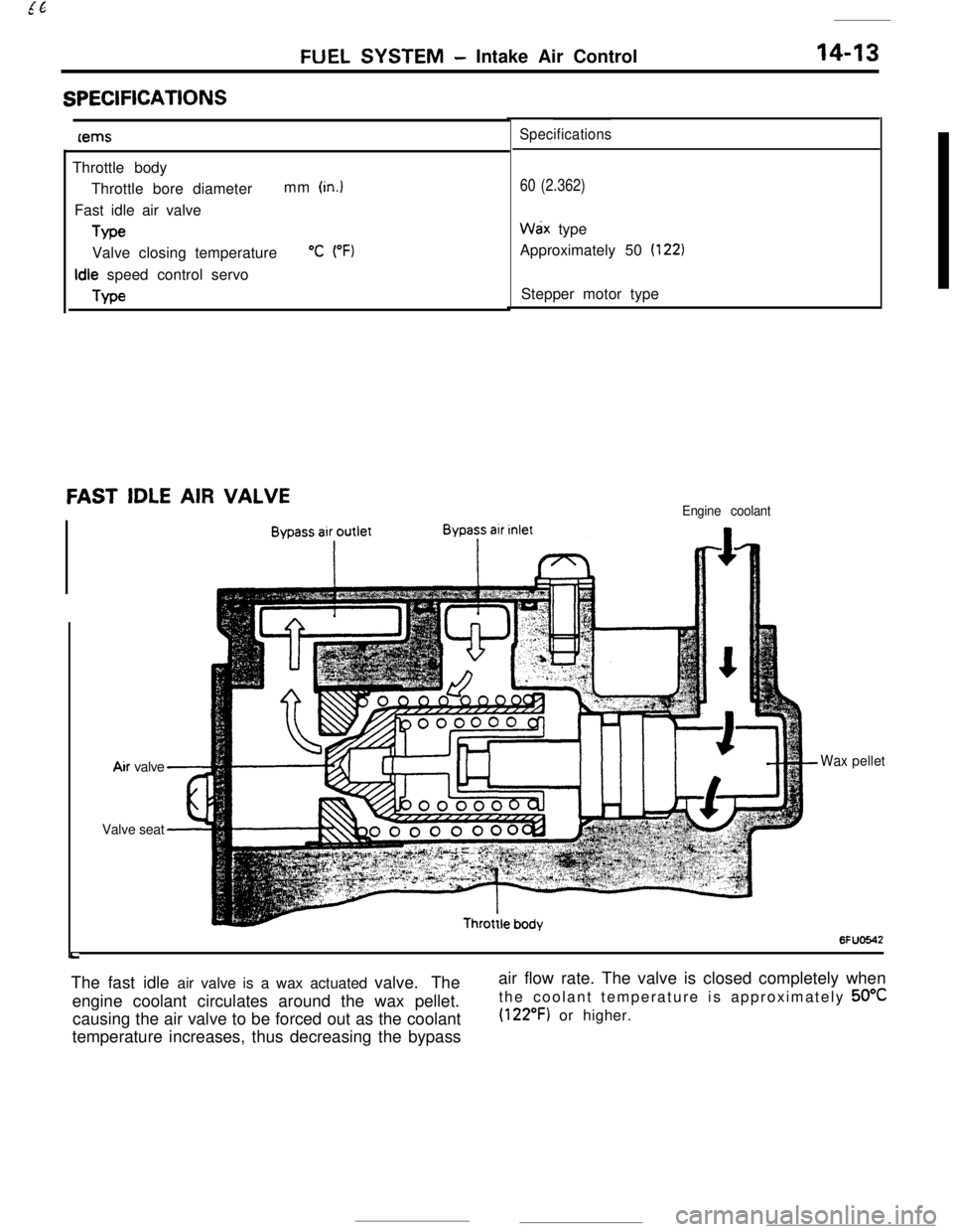
FAST IDLE AIR VALVEEngine coolant
LAir valve
Waxpellet
Valve seat
6FUO642The fast idle air valve is a wax actuated valve. The
engine coolant circulates around the wax pellet.
causing the air valve to be forced out as the coolant
temperature increases, thus decreasing the bypassair flow rate. The valve is closed completely when
the coolant temperature is approximately 50°C
(122°F) or higher.
Page 126 of 391
14-14
.._~- ---.FUEL SYSTEM
- Sensors
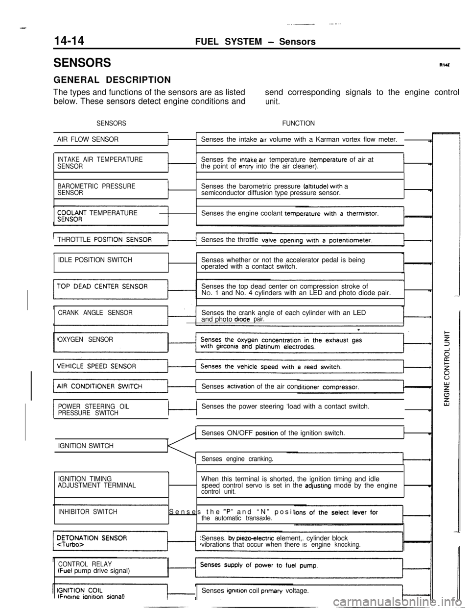
SENSORSRlUGENERAL DESCRIPTION
The types and functions of the sensors are as listedsend corresponding signals to the engine control
below. These sensors detect engine conditions and
unit.
SENSORSFUNCTION
AIR FLOW SENSOR
fSenses the intake arr volume with a Karman vortex flow meter.
INTAKE AIR TEMPERATURE
SENSORSenses the Intake air temperature (temperature of air at
the point of entry into the air cleaner).I
BAROMETRIC PRESSURE
SENSORISenses the barometric pressure faltrtude) wrth a
semiconductor diffusion type pressure sensor.
$;;OOf;T TEMPERATURESenses the engine coolant tern
THROTTLE
POSITISenses the throttle
tI
IDLE POSITION SWITCHSenses whether or not the accelerator pedal is being
operated with a contact switch.
Senses the top dead center on compression stroke of
NO. 1 and No. 4 cylinders with an LED and photo diode pair.
CRANK ANGLE SENSORSenses the crank angle of each cylinder with an LED
and photo diodepair.
T
OXYGEN SENSORSenses
actrvation of the air con
POWER STEERING OIL
PRESSURE SWITCHc-lSenses the power steering ‘load with a contact switch.
IGNITION SWITCHSenses ON/OFF
posrtion of the ignition switch.I
Senses engine cranking.
,
IGNITION TIMING
ADJUSTMENT TERMINALWhen this terminal is shorted, the ignition timing and idle
speed control servo is set in the adjustrng mode by the enginecontrol unit.
INHIBITOR SWITCHSenses the *P” and “N” positthe automatic transaxle.Senses.
by pieto-electric element,. cylinder block
vibrations that occur when there ISengineknocking.
CONTROL RELAY
(Fuel pump drive signal)
lFnorne ianitron sianal!Senses ignrtton coil prIman/ voltage.
Page 133 of 391
FUEL SYSTEM - Sensors14-21When exposed to light, the photo diode conducts
urrent in a direction opposite to an ordinary diode.
.s a result, current flows in the direction indicated
by the arrow and dotted line and a voltage (5 volts) isapplied to the comparator of the sensor unit so that
the terminal voltage of the engine control unit
becomes 5 volts. When the disc rotates further andthe slit moves beyond the space between the
LED/photo diode pair, the light can no longer reach
the photo diode, thus the current indicated by the
dotted line ceases to flow and the terminal voltage
of the engine control unit becomes 0 volt.
tn this
way, pulse signals are sent to the engine control
unit from the sensor unit.
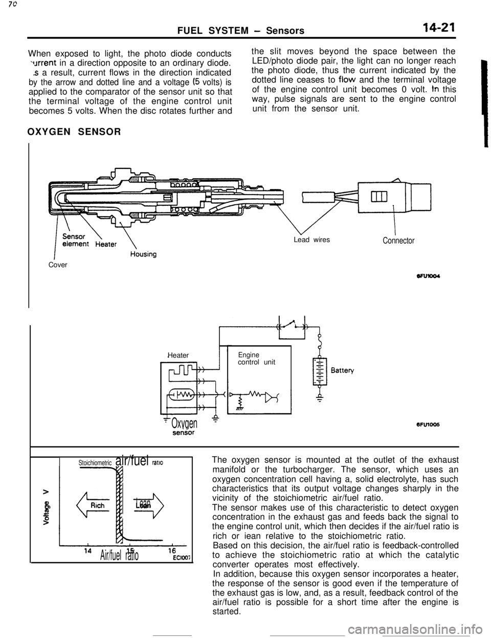
OXYGEN SENSOR
k
1 ~~~~t13ate~ousingCoverLead wiresConnectorHeater
Enginecontrol unit6FUlOO5
- Oxygen‘-serisor
The oxygen sensor is mounted at the outlet of the exhaust
manifold or the turbocharger. The sensor, which uses an
oxygen concentration cell having a, solid electrolyte, has such
characteristics that its output voltage changes sharply in the
vicinity of the stoichiometric air/fuel ratio.
The sensor makes use of this characteristic to detect oxygen
concentration in the exhaust gas and feeds back the signal to
the engine control unit, which then decides if the air/fuel ratio is
rich or iean relative to the stoichiometric ratio.
Based on this decision, the air/fuel ratio is feedback-controlled
to achieve the stoichiometric ratio at which the catalytic
converter operates most effectively.
In addition, because this oxygen sensor incorporates a heater,
the response of the sensor is good even if the temperature of
the exhaust gas is low, and, as a result, feedback control of the
air/fuel ratio is possible for a short time after the engine is
started.
Stoichiometric air/fuel ratlo
r3
Lean
Air/fuel ratioEC1007
Page 136 of 391
--
,
14-24FUEL SYSTEM - Sensors
POWER STEERING OIL PRESSURE SWITCHEngine control unit
Power steering oil
pressure switchBattery
voltage
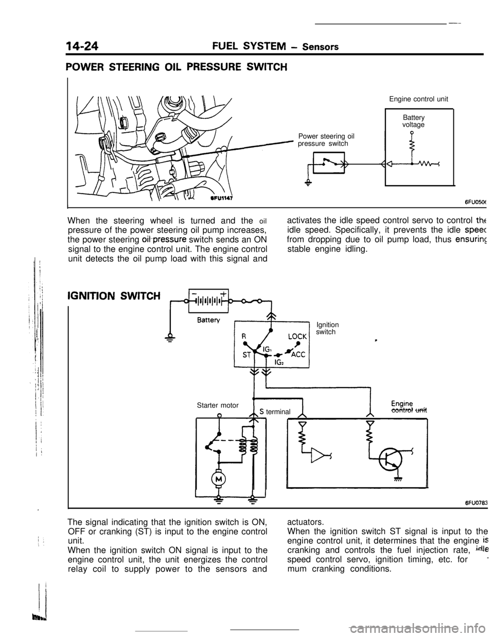
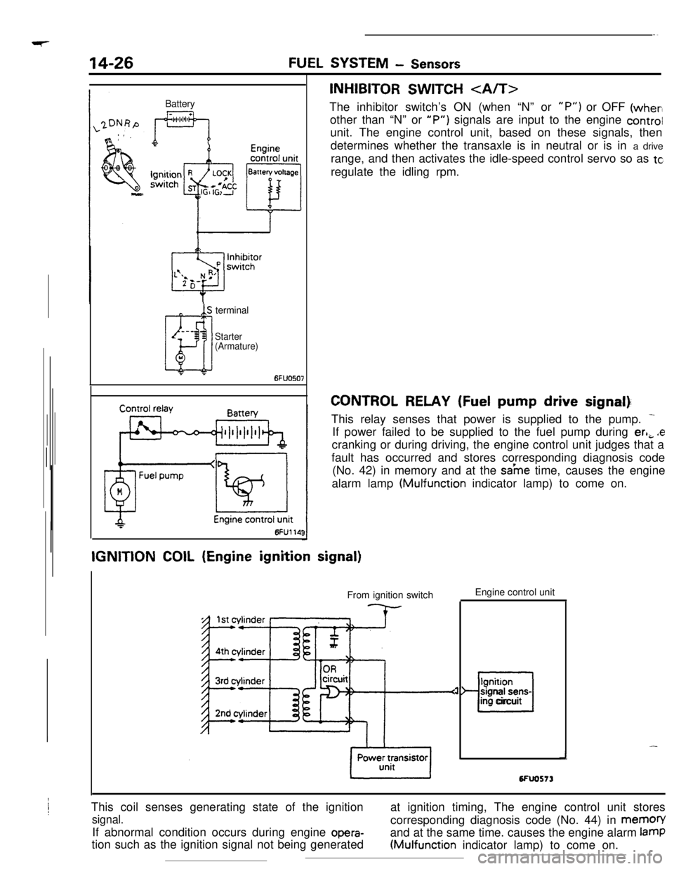
6FUO5OtIWhen the steering wheel is turned and the oil
pressure of the power steering oil pump increases,
the power steering oifpressure switch sends an ON
signal to the engine control unit. The engine control
unit detects the oil pump load with this signal andactivates the idle speed control servo to control
theidle speed. Specifically, it prevents the idle
speecfrom dropping due to oil pump load, thus
ensuringstable engine idling.IGNITION
SWITCH
1IBattery
Ignition
switch
Starter motor
aS terminalcontrol unit
6FUO762The signal indicating that the ignition switch is ON,
OFF or cranking (ST) is input to the engine control
unit.
When the ignition switch ON signal is input to the
engine control unit, the unit energizes the control
relay coil to supply power to the sensors and
actuators.When the ignition switch ST signal is input to the
engine control unit, it determines that the engine
iscranking and controls the fuel injection rate,
despeed control servo, ignition timing, etc. for
-mum cranking conditions.
Page 137 of 391

FUEL SYSTEM - Sensors14-25Terminal for
ignition timing
adjustment
l-l6FUO51:7
W$ht(/.
Piezo-electncelements
I6FUOSlO
DetonationEngine control
unit
sensor
I-
I t i A-- >--t.--‘-3 -
wt4rlIGNITION TlMlNG ADJUSTMENT TERMINAL
This terminal
is used when adjusting the basic ignition timing or
basic idle speed.
When this terminal is shorted to ground, the engine control unit
cancels the
ignition timing control and idle speed control, and
sets the ignition
timing and idle speed control servos in their
adjusting mode.
For the basic idle speed adjustment, the diagnosis terminal is
also shorted to ground.
DETONATION SENSOR
The detonation sensor is installed at a position where it can
detect, with a high degree of precision, knocking generated at
each cylinder; it detects cylinder block vibrations caused by
knocking, and outputs voltage proportional to the magnitude of
those vibrations.
Because cylinder block vibrations caused by knocking vary
from engine to engine, the engine control unit passes this
through a frequncy filter, detecting only the knocking, thus
resulting in a spark retardation of the ignition timing that
corresponds to the strength of the knocking.
Page 138 of 391
Page 145 of 391
FUEL SYSTEM- Fuel Injection Control14-33
FUEL INJECTI& CONTROLGENERAL DESCRIPTION
Air flow sensor
cBarometric Dressure sensor
Coolant
temr3erature sensorITop dead center sensor
ignition switch
-
c
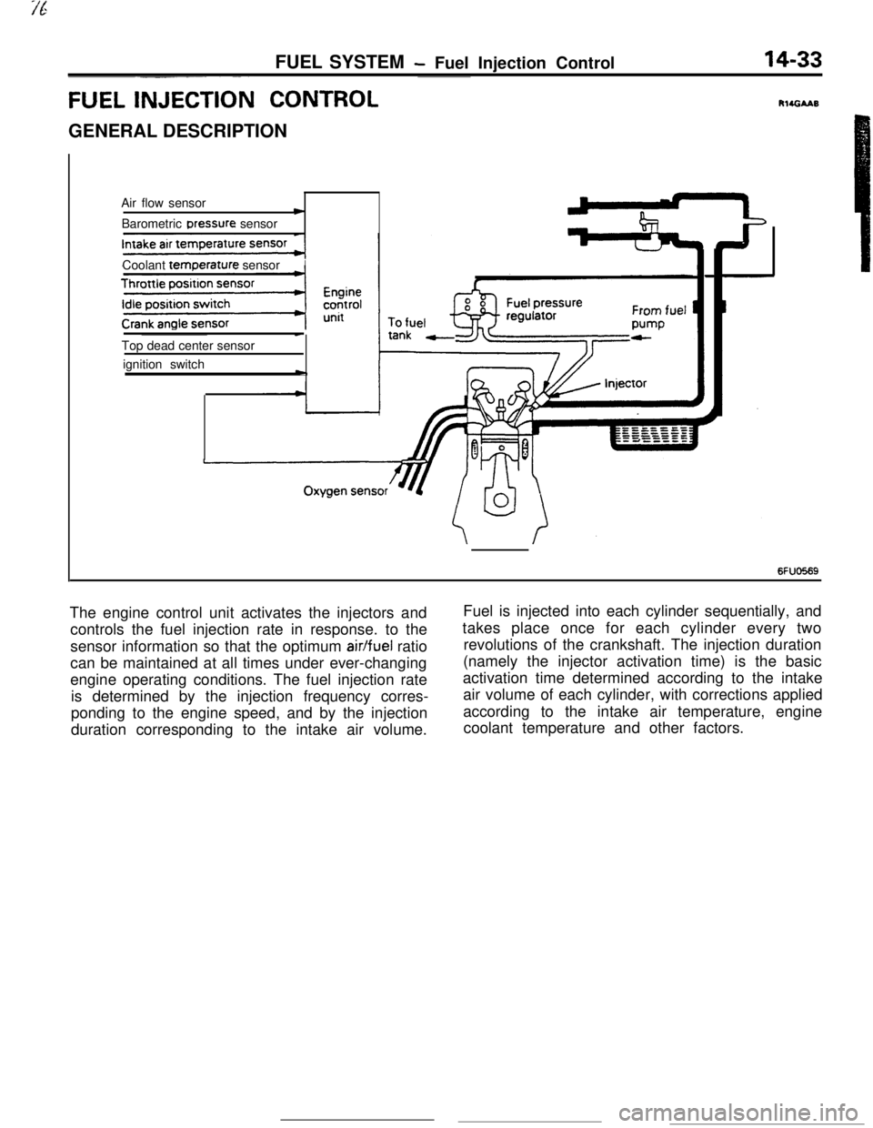
6FUO569The engine control unit activates the injectors andFuel is injected into each cylinder sequentially, and
controls the fuel injection rate in response. to thetakes place once for each cylinder every two
sensor information so that the optimum
air/fuel ratiorevolutions of the crankshaft. The injection duration
can be maintained at all times under ever-changing(namely the injector activation time) is the basic
engine operating conditions. The fuel injection rateactivation time determined according to the intake
is determined by the injection frequency corres-air volume of each cylinder, with corrections applied
ponding to the engine speed, and by the injectionaccording to the intake air temperature, engine
duration corresponding to the intake air volume.coolant temperature and other factors.
Page 148 of 391
14-36FUEL SYSTEM- Fuel lniection Control
SFUOSlS
RESISTOR
co,.of the injector.
Because the injector must respond instantly to fuel-injection
signals, the number of windings of the coil is reduced in order
to facilitate current rise when the current is flowing in the coil.
By doing so, the resistance of the injector coil becomes smaller
and a greater amount of current can flow, with the result that
the calorific value of the injector coil becomes greater, and
1overheating occurs.
For this reason, for turbocharger-equipped models (which have
low resistance of the injector coil), a resistor is provided
between the power supply (+) and the injector in order to
regulate the amount of current flowing in the coil.
FUEL INJECTION TIMING (INJECTOR AC-
TIVATION TIMING)
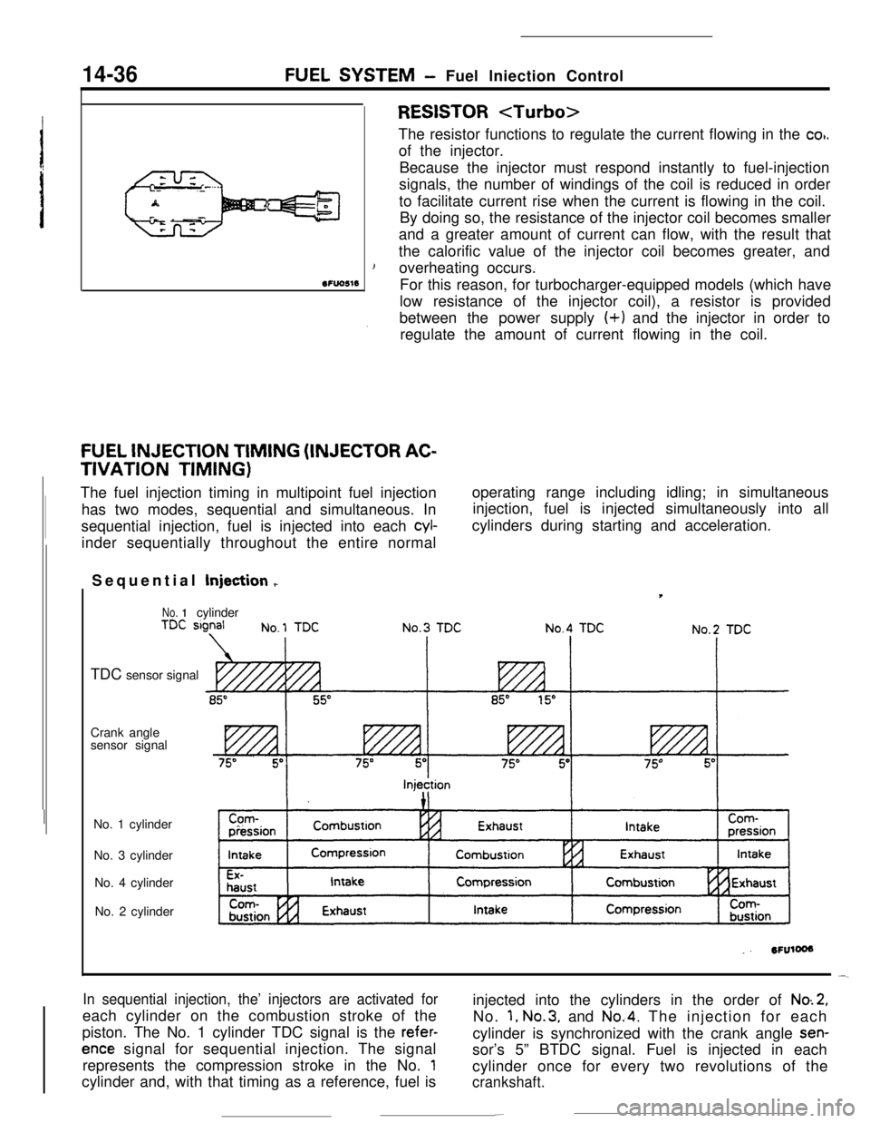
The fuel injection timing in multipoint fuel injection
has two modes, sequential and simultaneous. In
sequential injection, fuel is injected into each
cyl-inder sequentially throughout the entire normaloperating range including idling; in simultaneous
injection, fuel is injected simultaneously into all
cylinders during starting and acceleration.
Sequential Injection
r
No. 1cylinder
TDC sensor signal
Crank angle
sensor signal
No. 1 cylinder
No. 3 cylinder
No. 4 cylinder
No. 2 cylinder
In sequential injection, the’ injectors are activated foreach cylinder on the combustion stroke of the
piston. The No. 1 cylinder TDC signal is the
refer-
ence signal for sequential injection. The signal
represents the compression stroke in the No.
1cylinder and, with that timing as a reference, fuel isinjected into the cylinders in the order of
No.2,No.
1, No.3, and No.4. The injection for each
cylinder is synchronized with the crank angle
sen-sor’s 5” BTDC signal. Fuel is injected in each
cylinder once for every two revolutions of the
crankshaft.
-
Page 158 of 391
.
14-46FUEL SYSTEM- Idle Speed Control
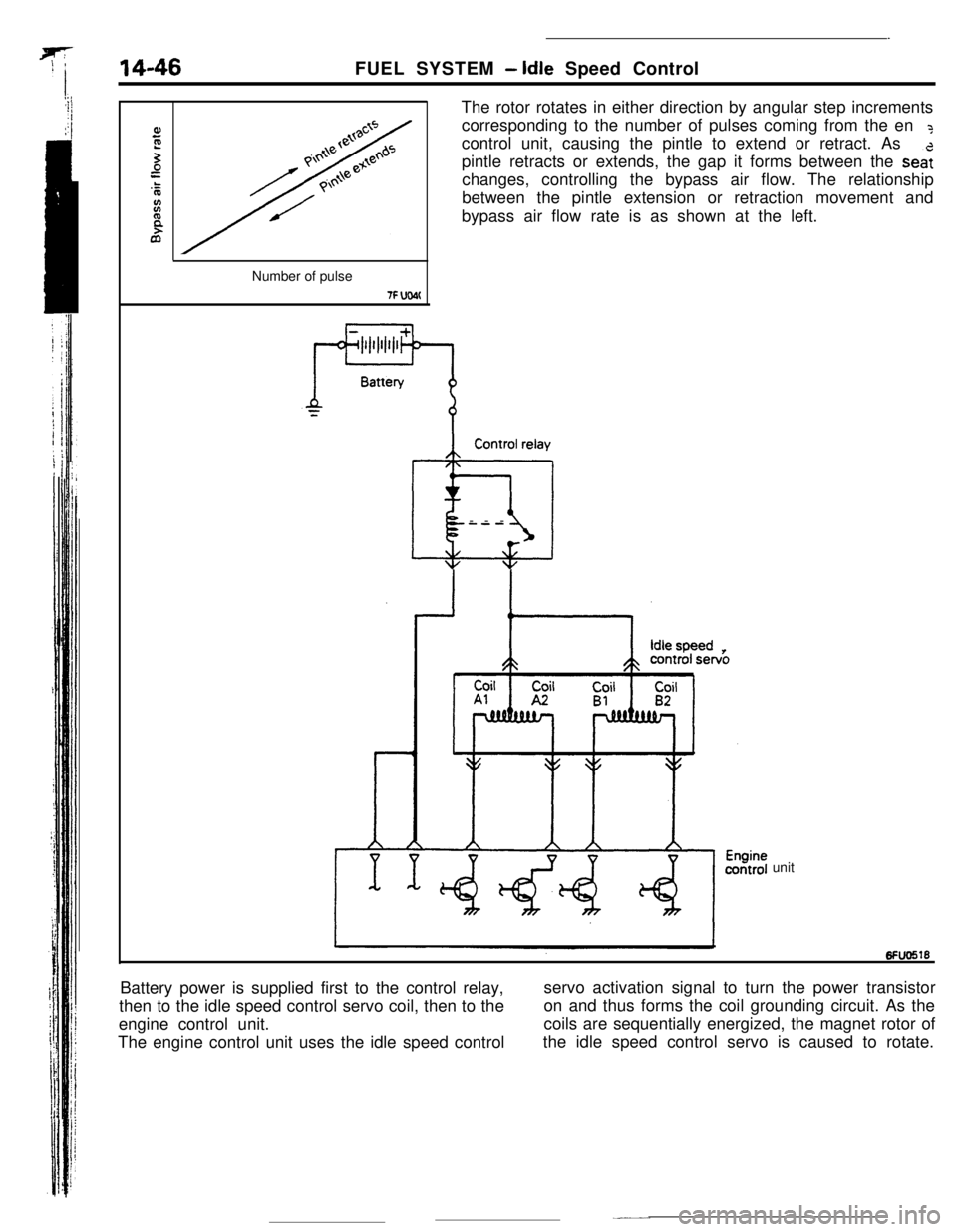
The rotor rotates in either direction by angular step increments
corresponding to the number of pulses coming from the en
?control unit, causing the pintle to extend or retract. As
pintle retracts or extends, the gap it forms between the
sea:changes, controlling the bypass air flow. The relationship
between the pintle extension or retraction movement and
bypass air flow rate is as shown at the left.
Number of pulse
7F UW(Control relay
@iI---
unit
Battery power is supplied first to the control relay,
then to the idle speed control servo coil, then to theservo activation signal to turn the power transistor
engine control unit.on and thus forms the coil grounding circuit. As the
The engine control unit uses the idle speed controlcoils are sequentially energized, the magnet rotor of
the idle speed control servo is caused to rotate.