ESP MITSUBISHI ECLIPSE 1990 Owner's Guide
[x] Cancel search | Manufacturer: MITSUBISHI, Model Year: 1990, Model line: ECLIPSE, Model: MITSUBISHI ECLIPSE 1990Pages: 391, PDF Size: 15.27 MB
Page 218 of 391
POWER STEERING -Pinion and Valve Assembly Construction
WHEN THE STEERING WHEEL IS TURNED TO
THE LEFT
IS-9
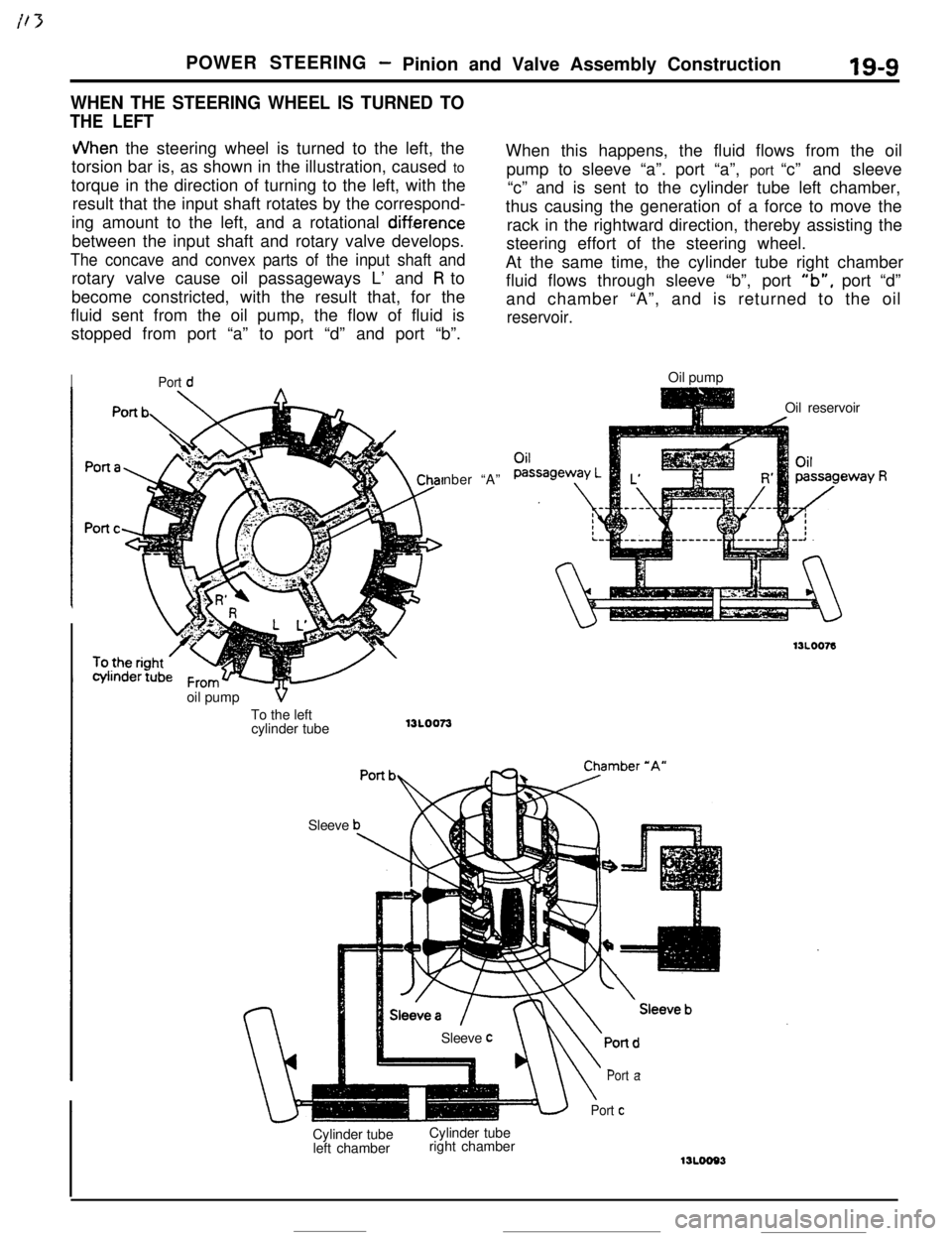
JVhen the steering wheel is turned to the left, the
torsion bar is, as shown in the illustration, caused to
torque in the direction of turning to the left, with the
result that the input shaft rotates by the correspond-
ing amount to the left, and a rotational
diff.erencebetween the input shaft and rotary valve develops.
The concave and convex parts of the input shaft androtary valve cause oil passageways L’ and
R to
become constricted, with the result that, for the
fluid sent from the oil pump, the flow of fluid is
stopped from port “a” to port “d” and port “b”.
IPort dnber “A”
SleeveWhen this happens, the fluid flows from the oil
pump to sleeve “a”. port “a”, port “c” and sleeve
“c” and is sent to the cylinder tube left chamber,
thus causing the generation of a force to move the
rack in the rightward direction, thereby assisting the
steering effort of the steering wheel.
At the same time, the cylinder tube right chamber
fluid flows through sleeve “b”, port
“b”, port “d”
and chamber “A”, and is returned to the oil
reservoir.Oil pump
Oil reservoir
Cylinder tube
left chamberCylinder tube
right chamber
\
Port a
Port cSleeve
coil pump
VTo the left
cylinder tube
13L0073
Page 220 of 391
POWER STEERING- Pinion and Valve Assembly Construction19-9
WHEN THE STEERING WHEEL IS TURNED TO
THE LEFT
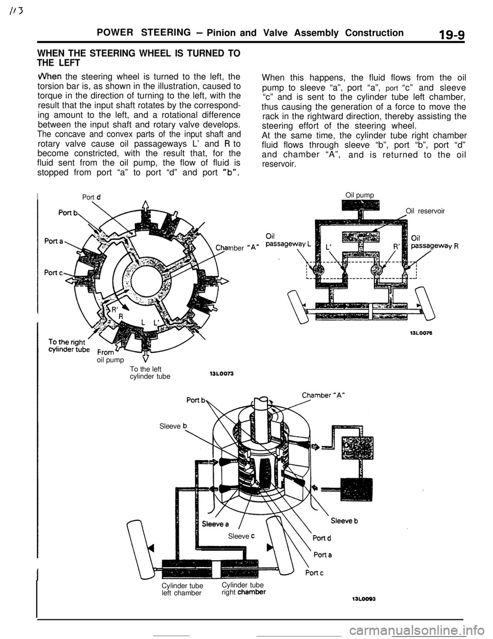
JVhen the steering wheel is turned to the left, the
torsion bar is, as shown in the illustration, caused to
torque in the direction of turning to the left, with the
result that the input shaft rotates by the correspond-
ing amount to the left, and a rotational difference
between the input shaft and rotary valve develops.
The concave and convex parts of the input shaft androtary valve cause oil passageways L’ and
R to
become constricted, with the result that, for the
fluid sent from the oil pump, the flow of fluid is
stopped from port “a” to port “d” and port
“b”.
IPort dnber
*oil pump
VTo the left
cylinder tube13LOO73
SleeveWhen this happens, the fluid flows from the oil
pump to sleeve “a”,port “a”, port “c” and sleeve
“c” and is sent to the cylinder tube left chamber,
thus causing the generation of a force to move the
rack in the rightward direction, thereby assisting the
steering effort of the steering wheel.
At the same time, the cylinder tube right chamber
fluid flows through sleeve “b”, port “b”, port “d”
and chamber “A”,
and is returned to the oil
reservoir.Oil pump
Oil reservoir
Sleeve
cCylinder tube
left chamberCylinder tube
right chamber
‘Y R
Page 244 of 391
-_ - .--.7
!21-20AUTOMATIC TRANSAXLE - A/T Safety-lock System
SHIFT LOCK DEVICE
When brake pedal is not depressed
Brake pedal link mechanismWhen brake pedal is depressed
Detent pin
Shift lock pini
Brake
Shift lock cable
-JIOuter cableInner cable
\\
/IShift loc&
OQAO155-
Ret& springOBAOl53
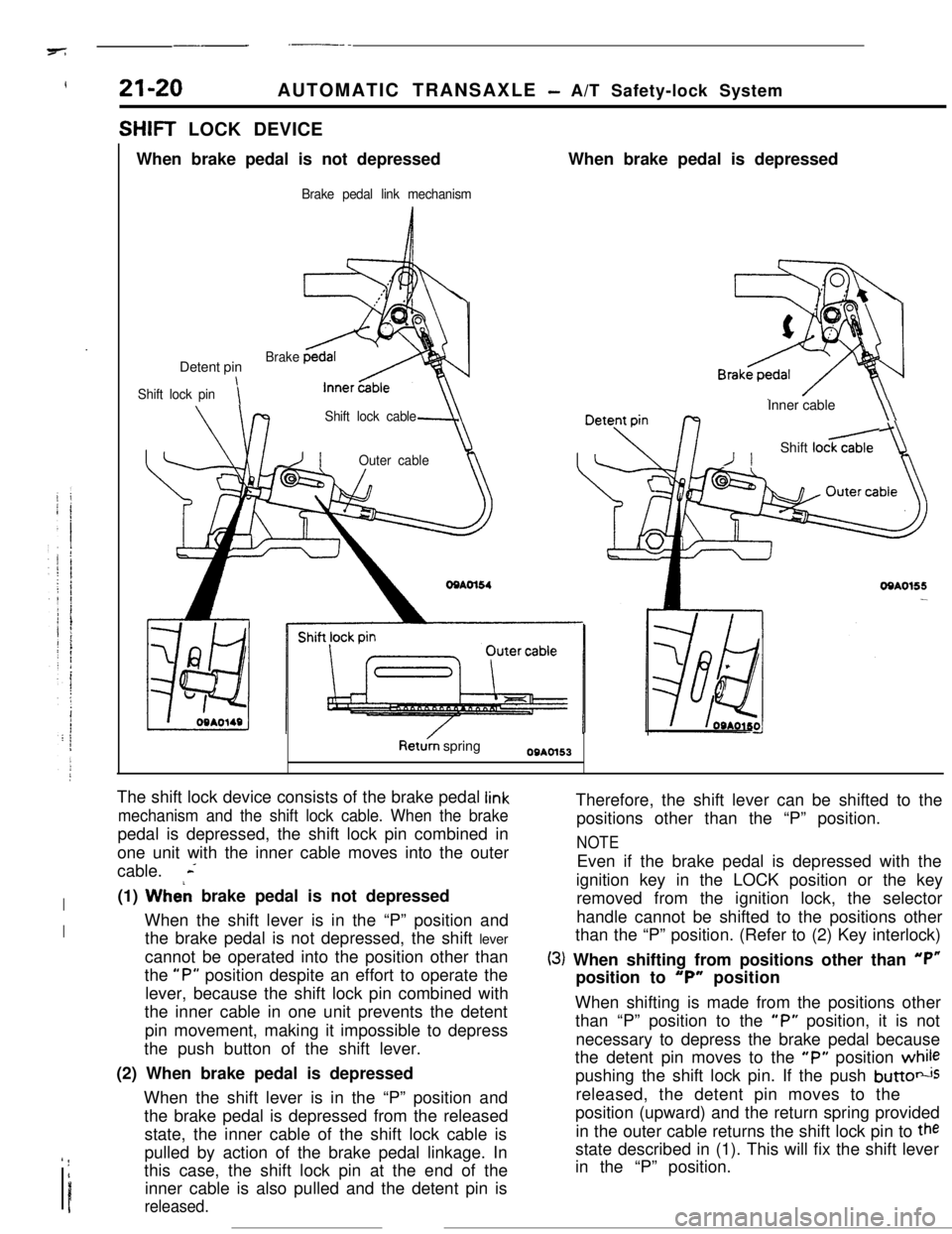
The shift lock device consists of the brake pedal
link
mechanism and the shift lock cable. When the brakepedal is depressed, the shift lock pin combined in
one unit with the inner cable moves into the outer
cable.
L
I(1) Wheh brake pedal is not depressed
IWhen the shift lever is in the “P” position and
the brake pedal is not depressed, the shift lever
cannot be operated into the position other than
the
“P” position despite an effort to operate the
lever, because the shift lock pin combined with
the inner cable in one unit prevents the detent
pin movement, making it impossible to depress
the push button of the shift lever.
(2) When brake pedal is depressed
When the shift lever is in the “P” position and
the brake pedal is depressed from the released
state, the inner cable of the shift lock cable is
’ !I
Ipulled by action of the brake pedal linkage. In
this case, the shift lock pin at the end of the
inner cable is also pulled and the detent pin isreleased.Therefore, the shift lever can be shifted to the
positions other than the “P” position.
NOTEEven if the brake pedal is depressed with the
ignition key in the LOCK position or the key
removed from the ignition lock, the selector
handle cannot be shifted to the positions other
than the “P” position. (Refer to (2) Key interlock)
(3) When shifting from positions other than “P”position to
“P” position
When shifting is made from the positions other
than “P” position to the
“P” position, it is not
necessary to depress the brake pedal because
the detent pin moves to the
“P” position whilepushing the shift lock pin. If the push
buttotisreleased, the detent pin moves to the
position (upward) and the return spring provided
in the outer cable returns the shift lock pin to
thestate described in (1). This will fix the shift lever
in the “P” position.
Page 247 of 391
I,?+7_-AUTOMATIC TRANSAXLE
- Transaxle Mechanism21-23
I IRS SP175003TC
: Torqueconverter
DC : Damper clutchCl : Front clutch
tPlanetan/
gear set
C2 : Rear clutchW : End clutchBl. : Kickdown brake82 : Low/reverse brake
OWC : One-way clutch
FS : Forward sun gearRS : Reverse sun gear
SP : Short pinion
LP : Long pinionAG : Annulus gearTRANSAXLE MECHANISM
fQlEMhGENERAL DESCRIPTION
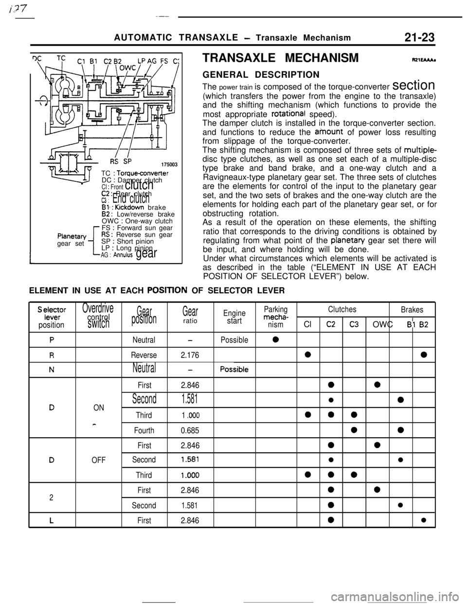
The power train is composed of the torque-converter section
(which transfers the power from the engine to the transaxle)
and the shifting mechanism (which functions to provide the
most appropriate
rotational speed).
The damper clutch is installed in the torque-converter section.
and functions to reduce the ainount of power loss resulting
from slippage of the torque-converter.
The shifting mechanism is composed of three sets of multiple-
disc type clutches, as well as one set each of a multiple-disc
type brake and band brake, and a one-way clutch and a
Ravigneaux-type planetary gear set. The three sets of clutches
are the elements for control of the input to the planetary gear
set, and the two sets of brakes and the one-way clutch are the
elements for holding each part of the planetary gear set, or for
obstructing rotation.
As a result of the operation on these elements, the shifting
ratio that corresponds to the driving conditions is obtained by
regulating from what point of the
planetan/ gear set there will
be input, and where holding will be done.
Under what circumstances which elements will be activated is
as described in the table (“ELEMENT IN USE AT EACH
POSITION OF SELECTOR LEVER”) below.
ELEMENT IN USE AT EACH
POSITtON OF SELECTOR LEVER
S ylele~rOverdriveGearGearEngineParkingClutches
Brakescontrolmecha-
positionswitchpositionratiostartnismCl c2C3 OWC Bl 82
PNeutral-Possible0
RReverse2.17600
NNeutral-Possible
First
2.8460a
Second1.581l0DON
Third1 .ooo000
e
Fourth0.68500
First2.84600
DOFFSecond1.581ll
Third1 .ooo000
First2.846002
Second1.5810l
LFirst2.8460l
Page 248 of 391
21-24AUTOMATIC TRANSAXLE - Transaxle Mechanism
SELECT PATTERN
Select pattern refers to the indication of transaxle
positions to be manually selected by the driver. This
transaxie is provided with 6 positions: P-R-N-D-
2-L. The following contains the explanations of the
function of each position selected.
P-Parking
(1)
(2)
(3)
Each element does not operate at all. Therefore,the engine output is not transmitted to the
output shaft.
The output shaft is completely locked by mecha-
nical means. Therefore, the vehicle does not
move in forward or reverse direction.
The engine can be started.
R-Reverse
(1) The vehicle moves in reverse direction.
(2) The engine cannot be started.
N-Neutral
(1) The engine output is not transmitted to the
output shaft as in the case of
“P”(2) The engine can be started.
D-Drive
(1)
(2)
(3)Corresponding with the degree that the
accelerator pedal is pressed down (i.e. throttle
opening) and vehicle speed,
“D” automatically
shifts between forward 4 speeds. Note, howev-
er,’ that the forward 3 speeds are selected when
the overdrive control switch is OFF. The automa-tic shifting (up or down) is performed according
to the shift pattern shown in the illustration on
page 2
l-30.Driving-off is always performed in
1st gear.Kickdown refers to the downshift that is per-
formed if the accelerator pedal is pressed down
(4)
(5)when the vehicle is running. in
2nd. 3rd or 4t,.
gear. It is performed when the load exceeds the
downshift point.
This function
IS useful when the driver isaccelerating to pass another vehicle.
Engine brake does not function when the shift is
in
1st gear.
When the vehicle is stopped, shifting is made to
the
2nd gear to minimize creep and vibration.
Upon starting, shifting is made to
1st gear.
S-Second
(1)
(2)
(3)“2” automatically shifts between
1st and 2ndgears. This means no upshift to
3rd gear occurs.
Driving-off is always performed in
1st gear.
Downshift to
2nd or 3rd gear is performed by
selecting the“2” range while the vehicle is
running in
3,rd or 4th gear, when a speed lower
than the set value is reached.
(4)As in the case of the “D” range, engine brake
does not work when the shift is in
1st gear.
L-Lock-up
(1)
(2)
(3)While “L” (Lock-up) performs downshift from
2nd to 1st gear, it does not shift up the gear
from
1st to 2nd or 3rd. The enables what is_.called
“1st gear holding”.
Driving-off is always performed in
1st gear.
Engine brake functions in the case of this
1st
gear..By selecting the “L” range while the vehicle is
running in the
“0” or “2” range, downshift from4th to
3rd, 3rd to 2nd, or 2nd to 1st is performed
when the vehicle reaches the respective speed
prescribed for each gear.
Page 253 of 391
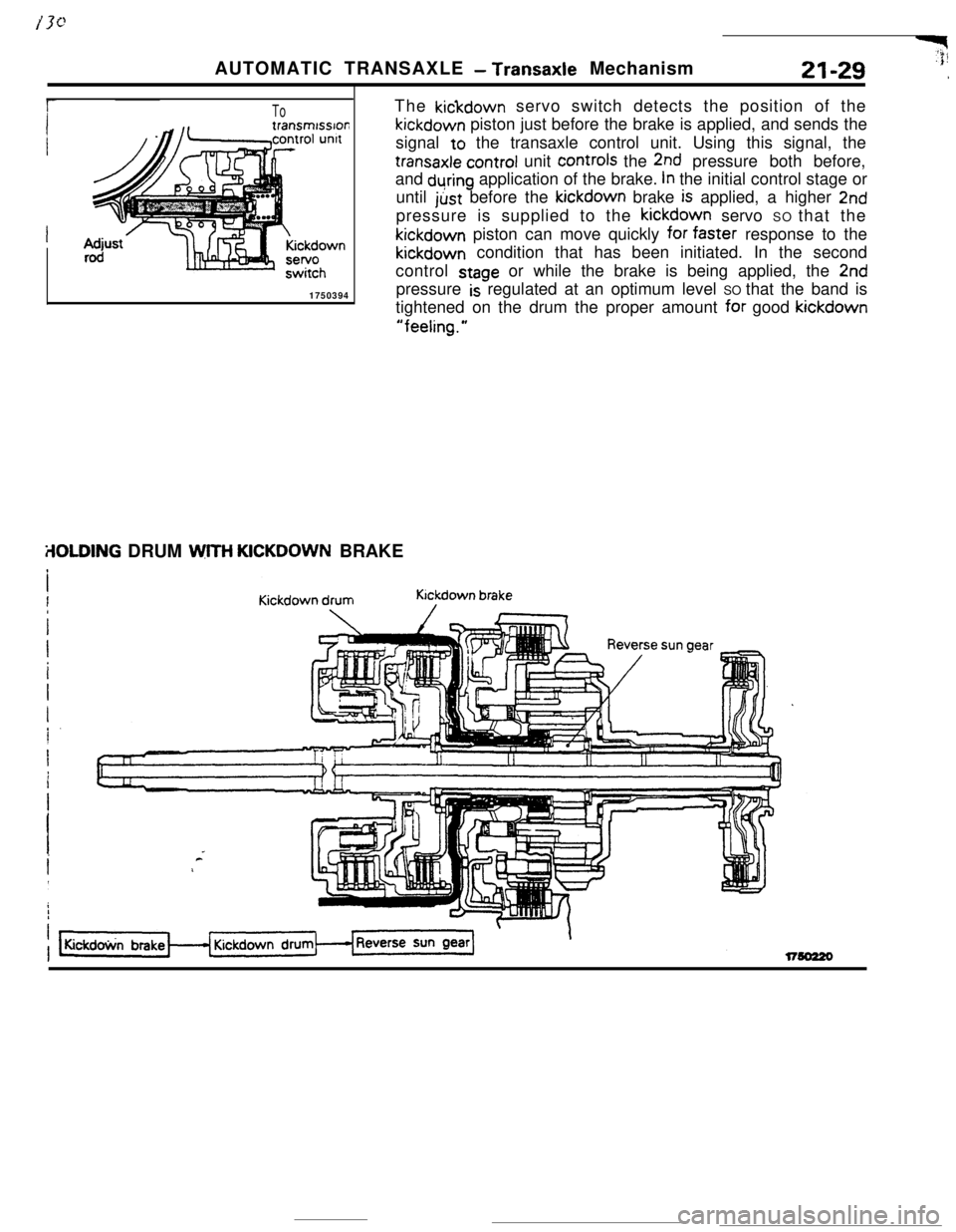
ToThe kickdown servo switch detects the position of thekickdown piston just before the brake is applied, and sends the
signal to the transaxle control unit. Using this signal, the
transaxle control unit controls the 2nd pressure both before,
and
during application of the brake. In the initial control stage or
until just before the kickdown brake
is applied, a higher 2ndpressure is supplied to the kickdown servo SO that thekickdown piston can move quickly for
faSter response to thekickdown condition that has been initiated. In the second
control
stage or while the brake is being applied, the 2nd
1750394pressure
is regulated at an optimum level SO that the band is
tightened on the drum the proper amount
for good kickdown
“feeling.”AUTOMATIC TRANSAXLE
- Transaxle MechanismY$21-29
,
ilOLDING DRUM WITH KICKDOWN BRAKE
Page 268 of 391
_-..21-44AUTOMATIC TRANSAXLE
- Transaxle Control
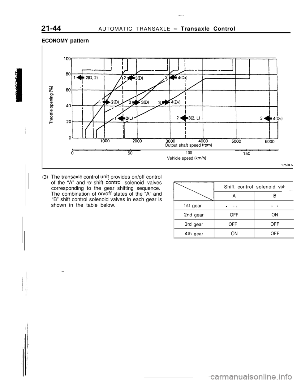
ECONOMY pattern
Output shaft speed
(rpm)
100Vehicle speed
(km/h)
1750471
(3)The transaxle control unit provides on/off control
of the “A” and “B” shift
controt solenoid valves
corresponding to the gear shifting sequence.
The combination of on/off states of the “A” and
“B” shift control solenoid valves in each gear is
shown in the table below.
1st gear
2nd gear
3rd gear
4th gearShift control solenoid
val.A
6 -l ONON
OFFON
OFFOFF
ONOFF
c
Page 269 of 391
‘4) Once the operation is step (2) is completed, the
hydraulic control device functions by hydraulic
pressure force to change the state of the
clutches and brakes to accomplish the gear
shifting. To minimize the shock that would
otherwise be produced during gear shifting,
hydraulic pressure is controlled during the gear
shifting period by the “duty control” of the
pressure control solenoid valve. The duty control
is explained later.
‘HYDRAULIC PRESSURE CONTROL DURING
SHFIING(1) The hydraulic pressure that functions during
gear shifting to engage the clutches and apply
the brakes is regulated by the pressure control
valve, The hydraulic pressure that works on the
pressure control valve is further regulated by the
pressure control solenoid valve which functions
under the control of the transaxle control unit.
The transaxle control unit controls the solenoid
valve through the duty control, thus providing
appropriate regulation of the hydraulic pressure.
(2)
(3)
(4)The transaxle control unit decides the timing of
the gear shifting period (during which ‘it per-
forms hydraulic pressure control for gear shift-
ing) according to the change in the kickdown
drum rotating speed that it detects. The unit
identifies the time just before the kickdown
brake is applied and uses that as the timing for
initiating control of the hydraulic pressure which
is to be applied to the kickdown brake.
When the transaxle is cold, the fluid viscosity is
high, causing slower oil pressure response. in
such conditions, the transaxle control unit pro-
vides a correction for the oil pressure by
changing the control duty of the pressure control
solenoid valve.
This control is performed when the fluid temper-
atures as indicated by the oil temperature
sensor is lower than
60°C (140°F).After the engine has been started and the
vehicle is inmotion, the transaxle
continues torefine its performance
est possiblegear shifting.control unit
for smooth-
tHFigure B
- Duty(%)
17500661750067
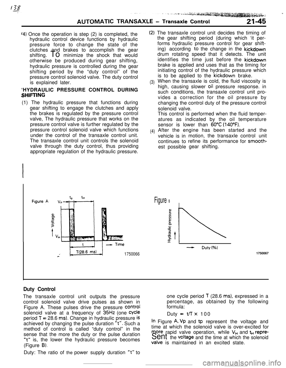
Duty ControlThe transaxle control unit outputs the pressureone cycle period
T (28.6 ms), expressed in a
control solenoid valve drive pulses as shown inpercentage, as obtained by the following
formula:
Figure A. These pulses drive the pressure
COrmIsolenoid valve at a frequency of
35Hz (one Cycleperiod
T = 28.6 ms). Change in hydraulic pressure iSDuty =t/-r x 100
achieved by changing the pulse duration
“t”. Such aIn Figure A, Vp and tp represent the voltage and
method of control is called “duty control” in thetime at which the solenoid valve is over-excited for
sense that the more the duty or the pulse duration
more rapid valve operation, while V,, and t+., repre-
“t” is, the lower the hydraulic pressure becomesSent the v,oltage and the time at which the solenoid(Figure
B).Valve is maintained in an excited state.
Duty: The ratio of the power supply duration
“t” to
Page 270 of 391
---21-46AUTOMATIC TRANSAXLE
- Transaxle Control
Figure A
IICITime (sec.)f
IiFigureB ,
II
cGear Shift Operation
(3rd to 4th)While the vehicle is being drive in
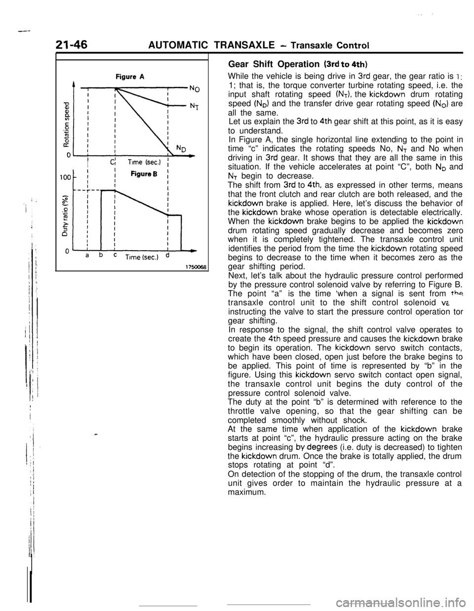
3rd gear, the gear ratio is I :1; that is, the torque converter turbine rotating speed, i.e. the
input shaft rotating speed
(NT), the kickdown drum rotating
speed
(No) and the transfer drive gear rotating speed (No) are
all the same.
Let us explain the
3rd to 4th gear shift at this point, as it is easy
to understand.
In Figure A, the single horizontal line extending to the point in
time “c” indicates the rotating speeds No,
NT and No when
driving in
3rd gear. It shows that they are all the same in this
situation. If the vehicle accelerates at point “C”, both
No and
NT begin to decrease.
The shift from
3rd to 4th, as expressed in other terms, means
that the front clutch and rear clutch are both released, and thekickdown brake is applied. Here, let’s discuss the behavior of
the kickdown brake whose operation is detectable electrically.
When the kickdown brake begins to be applied the kickdown
drum rotating speed gradually decrease and becomes zero
when it is completely tightened. The transaxle control unit
identifies the period from the time the kickdown rotating speed
begins to decrease to the time when it becomes zero as the
gear shifting period.
Next, let’s talk about the hydraulic pressure control performed
by the pressure control solenoid valve by referring to Figure B.
The point “a”is the time ‘when a signal is sent from tbg
transaxle control unit to the shift control solenoid
viinstructing the valve to start the pressure control operation tor
gear shifting.
In response to the signal, the shift control valve operates to
create the 4th speed pressure and causes the kickdown brake
to begin its operation. The kickdown servo switch contacts,
which have been closed, open just before the brake begins to
be applied. This point of time is represented by “b” in the
figure. Using this kickdown servo switch contact open signal,
the transaxle control unit begins the duty control of the
pressure control solenoid valve.
The duty at the point “b” is determined with reference to the
throttle valve opening, so that the gear shifting can be
completed smoothly without shock.
At the same time when application of the kickdown brake
starts at point “c”, the hydraulic pressure acting on the brake
begins increasing by.degrees (i.e. duty is decreased) to tighten
the kickdown drum. Once the brake is totally applied, the drum
stops rotating at point “d”.
On detection of the stopping of the drum, the transaxle control
unit gives order to maintain the hydraulic pressure at a
maximum.
Page 274 of 391
21-50AUTOMATIC TRANSAXLE - Transaxle Control
Vehicle
sensorspeedTerminal voltage
(VI
1
5
\*Fluidtemperature
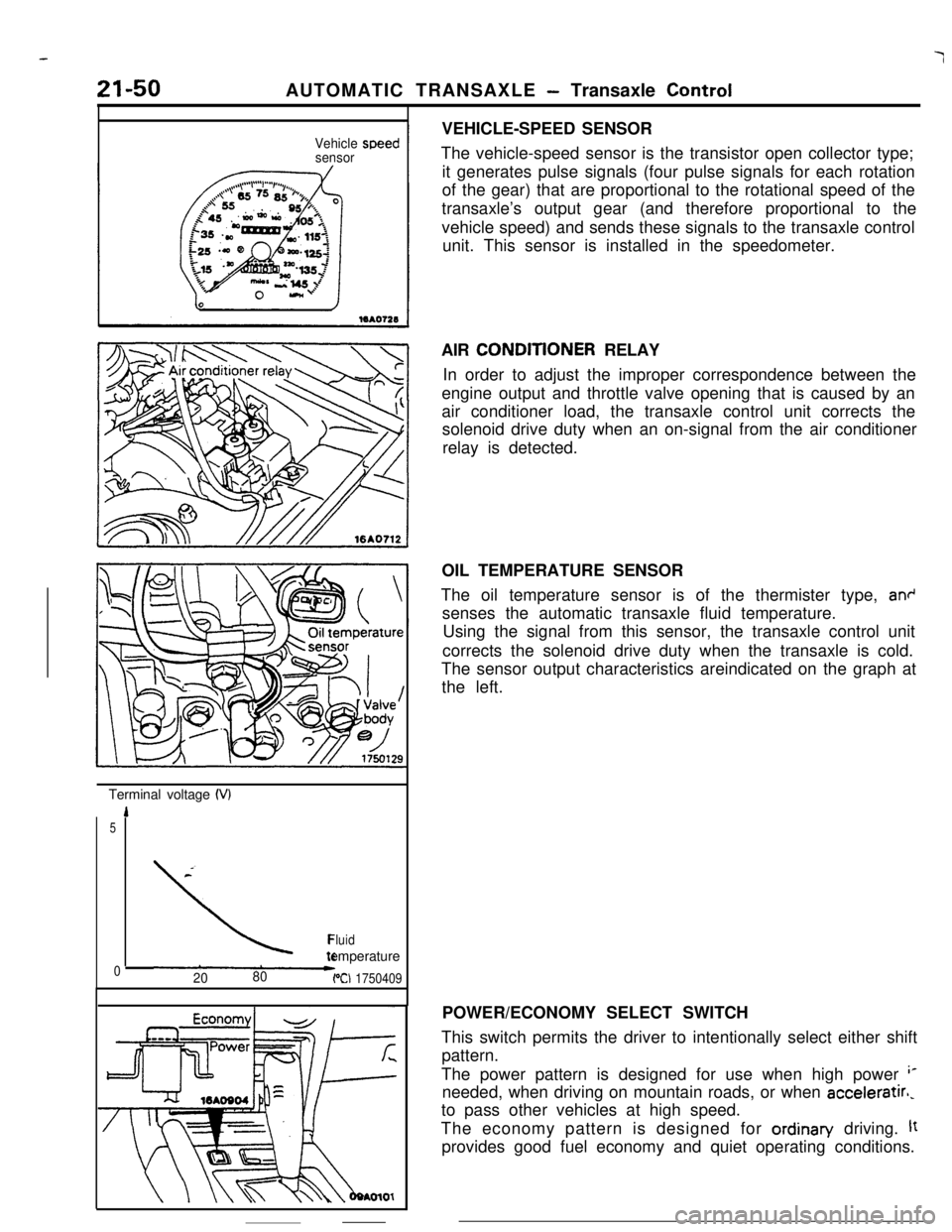
02080PCI 1750409VEHICLE-SPEED SENSOR
The vehicle-speed sensor is the transistor open collector type;
it generates pulse signals (four pulse signals for each rotation
of the gear) that are proportional to the rotational speed of the
transaxle’s output gear (and therefore proportional to the
vehicle speed) and sends these signals to the transaxle control
unit. This sensor is installed in the speedometer.
AIR CONDlTlONER RELAY
In order to adjust the improper correspondence between the
engine output and throttle valve opening that is caused by an
air conditioner load, the transaxle control unit corrects the
solenoid drive duty when an on-signal from the air conditioner
relay is detected.
OIL TEMPERATURE SENSOR
The oil temperature sensor is of the thermister type,
an+senses the automatic transaxle fluid temperature.
Using the signal from this sensor, the transaxle control unit
corrects the solenoid drive duty when the transaxle is cold.
The sensor output characteristics areindicated on the graph at
the left.
POWER/ECONOMY SELECT SWITCH
This switch permits the driver to intentionally select either shift
pattern.
The power pattern is designed for use when high power
‘*needed, when driving on mountain roads, or when acceleratirl,
to pass other vehicles at high speed.
The economy pattern is designed for ordinan/ driving.
ltprovides good fuel economy and quiet operating conditions.