diagram MITSUBISHI ECLIPSE 1990 Service Manual
[x] Cancel search | Manufacturer: MITSUBISHI, Model Year: 1990, Model line: ECLIPSE, Model: MITSUBISHI ECLIPSE 1990Pages: 391, PDF Size: 15.27 MB
Page 4 of 391
._._ -_- 1 -.
MODEL INDICATIONS
The following abbreviations are used in this manual for classification of model types.\
M/T: Indicates the manual transaxle, or models equipped ‘with the manual t\
ransaxle.
A/T: Indicates the automatic transaxle, or models equipped with the automatic\
transaxle.
MPI: Indicates the multi-point injection, or engines equipped with the multi-\
point injection.
DOHC: Indicates an engine with the double overhead camshaft, or a model equipp\
ed with such an engine,
Turbo: Indicates an engine with turbocharger, or a model equipped with such an \
engine.
2WD: Indicates the front wheel-drive vehicles.
4WD: Indicates the 4 wheel-drive vehicles.
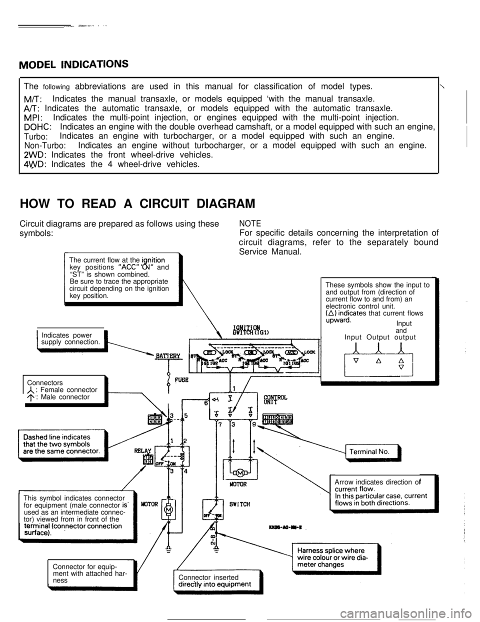
HOW TO READ A CIRCUIT DIAGRAM
initionkey positions “ACC” ” N” and8“ST” is shown combined.
~
Service Manual.
o&ficates that current flows
Input
1 Indicates power1supply connection.
A : Female connector9.1 Male connector
\ Il-4’
Input Output output
is..used as an intermediate connec-
Page 20 of 391
2-2
t
featuring light unsprung weight.
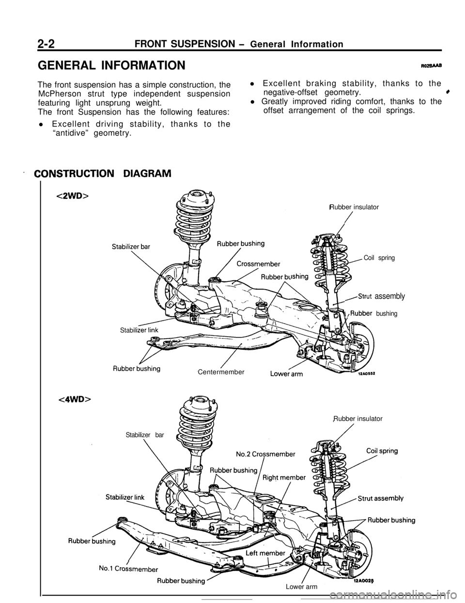
. CONSTRUCTION DIAGRAM
<2WD>
<4WD>
Rubber insulator
/
lshing
Coil spring
,Strut assembly
I ,Rubber bushing
Stabili
Lowecarm
Rubber insulator
No.1 Crokmember
- -12AOO25Lower arm
Page 29 of 391
-.-...- ..v:T
3-2REAR AXLE- General Information
GENERAL INFORMATION
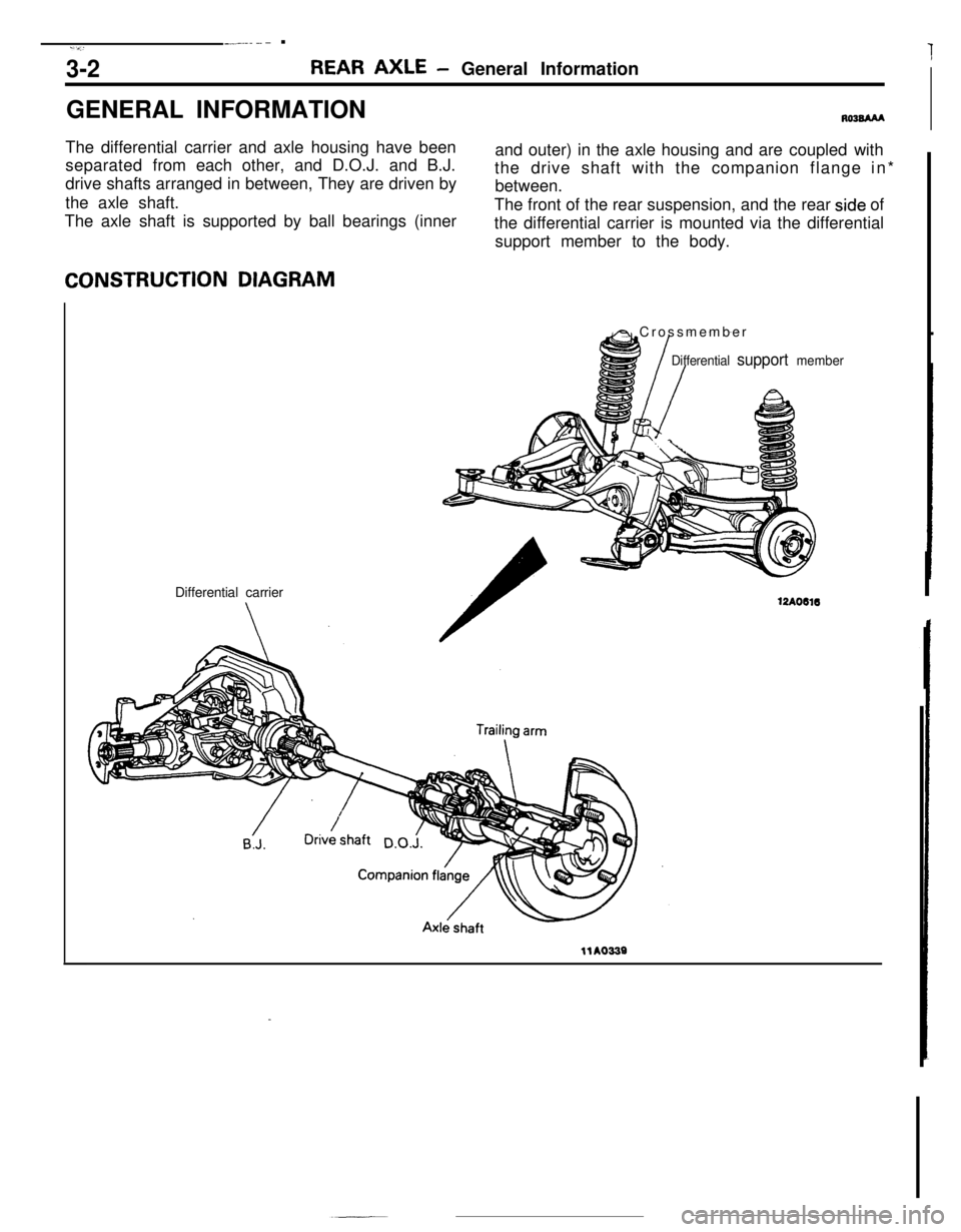
RO3BAAAThe differential carrier and axle housing have been
separated from each other, and D.O.J. and B.J.
drive shafts arranged in between, They are driven by
the axle shaft.
The axle shaft is supported by ball bearings (innerand outer) in the axle housing and are coupled with
the drive shaft with the companion flange in*
between.
The front of the rear suspension, and the rear
side of
the differential carrier is mounted via the differential
support member to the body.CONSTRUCTION DIAGRAM
Differential carrier
A Crossmember
Differential support member
12AO616
llA0339
Page 43 of 391
PARKING BRAKE
BRAKES- Parking Brake5-7
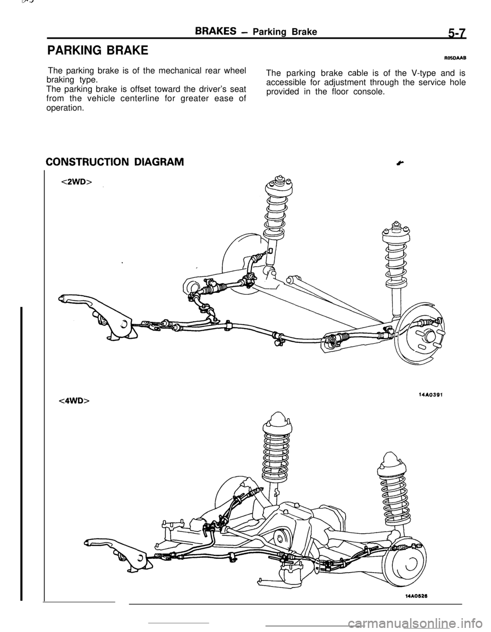
ROSDMBThe parking brake is of the mechanical rear wheel
braking type.The parking brake
cable is of the V-type and is
The parking brake is offset toward the driver’s seataccessible for adjustment through the service hole
provided in the floor console.
from the vehicle centerline for greater ease of
operation.CONSTRUCTION DIAGRAM
Y14AO391
<4WD>14A0626
Page 57 of 391
3i
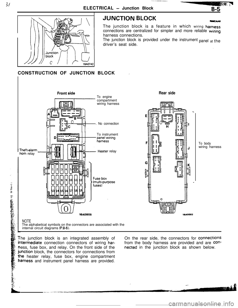
ELECTRICAL - Junction Block8-5JUNCTION
BLOCKThe junction block is a feature in which wiring
hamess
connections are centralized for simpler and more reliable wiringharness connections.
The junction block is provided under the instrumentdriver’s seat side.panelat the
CONSTRUCTION OF JUNCTION BLOCK
_.rheft-alarm
iom relay
To enginecompartment
wiring harness
. No connectionTo instrument
;;;+$ring
.’ ./%A0805relay
Rear side
NOTEThe alphabetical symbols on the connectors are associated with the
internal circuit diagrams
(PB-6).To bodywiring harness
he junction block is an integrated assembly ofltermediate connection connectors of wiring
har-ess, fuse box, and relay. On the front side of the
unction block, the connectors for connections from
le heater relay, fuse box, engine compartment
amess and instrument panel harness are provided.On the rear side, the connectors for connections
from the body harness are provided and are
con-
netted in the junction block as shown below.
Page 58 of 391
__._._ -.. .-
8-6ELECTRICAL - Junction Block
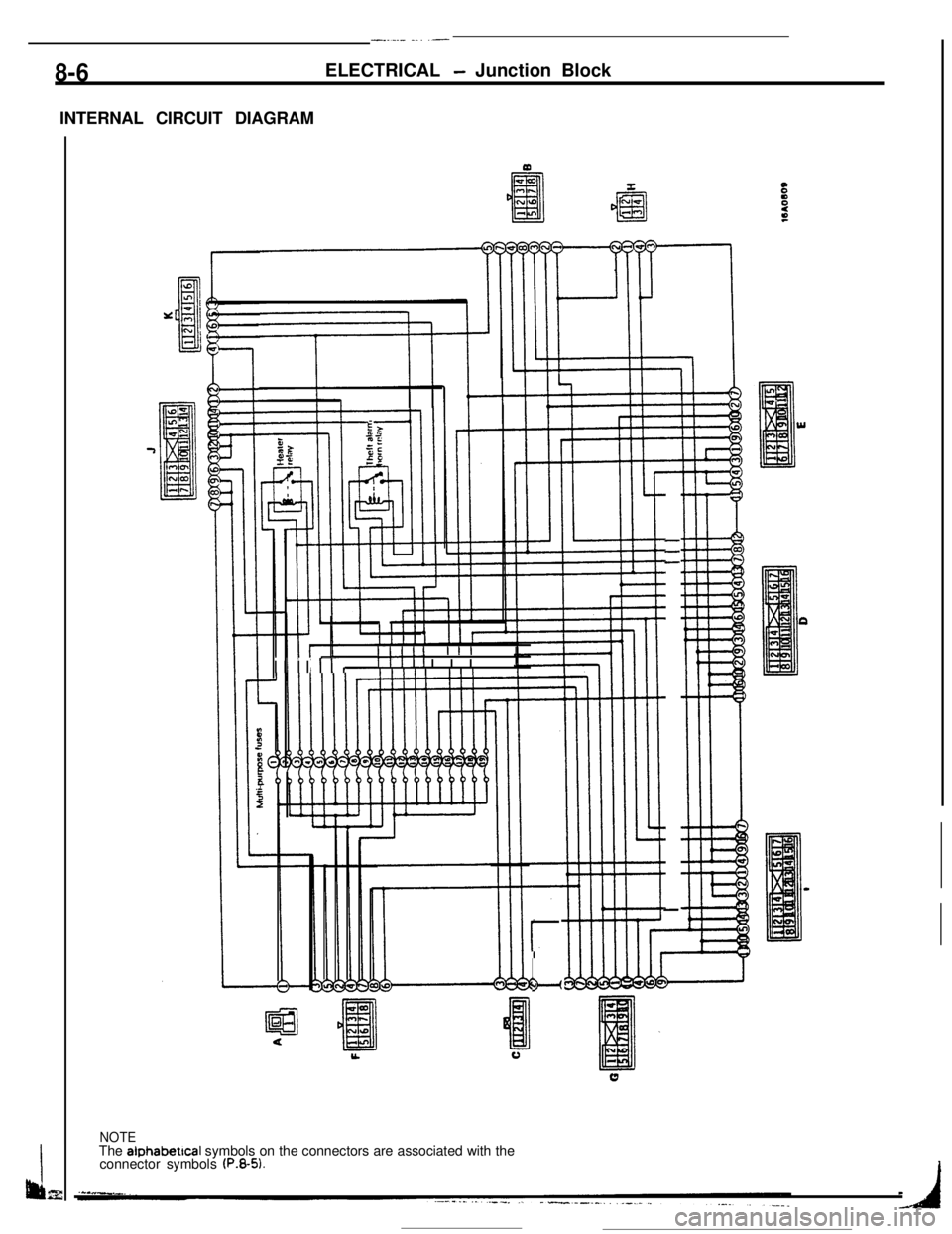
INTERNAL CIRCUIT DIAGRAM
---
-
Illll IIII
I II Irr,Illll IIII
r
L”
NOTEThe alphabetical symbols on the connectors are associated with the
connector symbols
(P.8-5).
Page 80 of 391
8-28ELECTRICAL- Engine Electrical
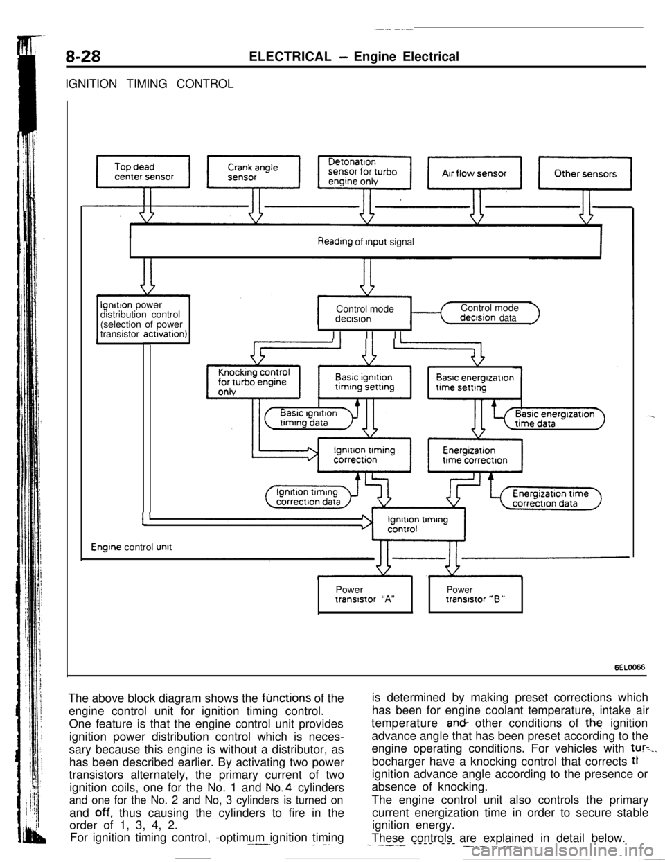
IGNITION TIMING CONTROL
Reading of Input signallgnitlon power
distribution control
(selection of power
transistor actlvatlon)Control mode
I II II IControl mode
dectsion data
Basic energlzatlon
I’
Engine control unitPower
Powertranststor “A”tranststor “B”
6ELOO66The above block diagram shows the
fljnctions of the
engine control unit for ignition timing control.
One feature is that the engine control unit provides
ignition power distribution control which is neces-
sary because this engine is without a distributor, as
has been described earlier. By activating two power
transistors alternately, the primary current of two
ignition coils, one for the No. 1 and No.4 cylinders
and one for the No. 2 and No, 3 cylinders is turned onand
off. thus causing the cylinders to fire in the
order of 1, 3, 4, 2.
For ignition timing control, -optimum ignition timing.^--_
_. -.is determined by making preset corrections which
has been for engine coolant temperature, intake air
temperature an& other conditions of the ignition
advance angle that has been preset according to the
engine operating conditions. For vehicles with
tur=_.bocharger have a knocking control that corrects tl
ignition advance angle according to the presence or
absence of knocking.
The engine control unit also controls the primary
current energization time in order to secure stable
ignition energy.
These controls are explained in detail below.
--. .----- ---- --- ___. .-. ___.,.__
Page 106 of 391
L1ENGINE
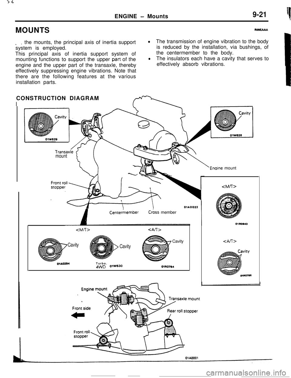
- Mounts9-21MOUNTS
Rost3u
. *the mounts, the principal axis of inertia support
system is employed.
This principal axis of inertia support system of
mounting functions to support the upper
part of the
engine and the upper part of the transaxle, thereby
effectively suppressing engine vibrations. Note that
there are the following features at the various
installation parts.
lThe transmission of engine vibration to the body
is reduced by the installation, via bushings, of
the centermember to the body.
lThe insulators each have a cavity that serves to
effectively absorb vibrations.
CONSTRUCTION DIAGRAM
I
Transaxlemount
‘i::
+g
/v 1b-8
8-,
Enaine mount
A
CenterkemberC&s member
Cavity
CavityCavityolAO284Turbo.
4WD 0lW630OlRO764
Page 112 of 391
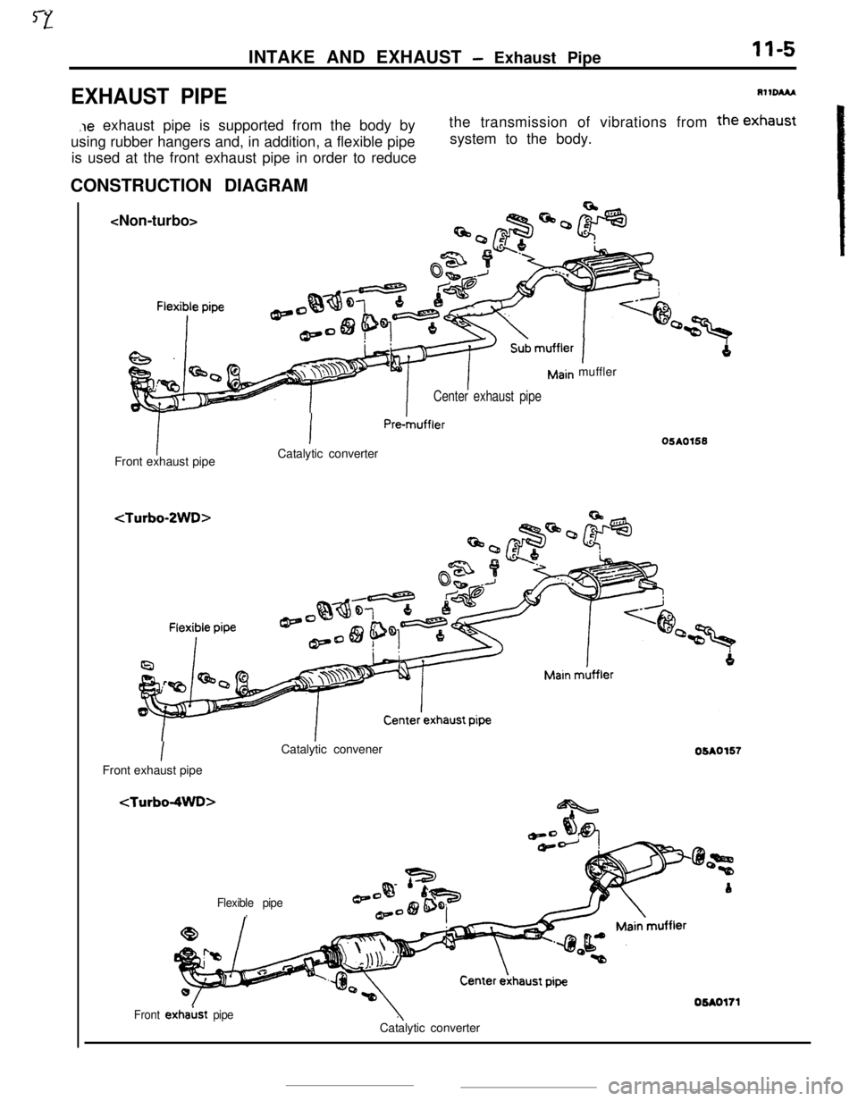
INTAKE AND EXHAUST - Exhaust PipeII-5
EXHAUST PIPERllDAM
,le exhaust pipe is supported from the body by
using rubber hangers and, in addition, a flexible pipe
is used at the front exhaust pipe in order to reducethe transmission of vibrations from the exhaust
system to the body.
CONSTRUCTION DIAGRAM
Center exhaust pipeFront exhaust pipe
IPm-muffler
Catalytic converter
Imuffler
IFront exhaust pipeCatalytic convener
Flexible pipe,05AO155
05A0157
Front exhakt pipeCatalytic converter
Page 121 of 391
FUEL SYSTEM -Fuel Supply and Fuel Pressure Control14-9
03Poo4:Diaphragm
from intake
4Fuel from delivery pipe
4m
B(42.7)QQ
2
sl -196 2
(26.4) g
t
$!a d
9
0)Positive5 z‘. pressure
(E.2)
w
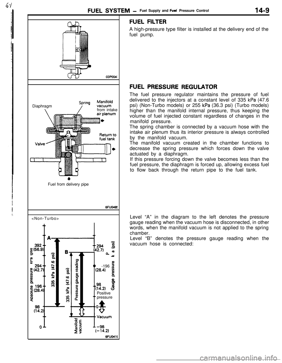
FUEL FILTERA high-pressure type filter is installed at the delivery end of the
fuel pump.
FUEL PRESSURE REGULATORThe fuel pressure regulator maintains the pressure of fuel
delivered to the injectors at a constant level of 335
kPa (47.6
psi) (Non-Turbo models) or 255
kPa (36.3 psi) (Turbo models)
higher than the manifold internal pressure, thus keeping the
volume of fuel injected constant regardless of changes in the
manifold pressure.
The spring chamber is connected by a vacuum hose with the
intake air plenum thus its interior pressure is always controlled
by the manifold vacuum.
The manifold vacuum created in the chamber functions to
decrease the spring pressure which forces down the valve
actuated by a diaphragm.
If this pressure forcing down the valve becomes less than the
fuel pressure, the diaphragm is forced up, allowing excess fuel
to flow back through the return pipe to the fuel tank.
Level “A” in the diagram to the left denotes the pressure
gauge reading when the vacuum hose is disconnected, in other
words, when the manifold vacuum is not applied to the spring
chamber.Level “B” denotes the pressure gauge reading when the
vacuum hose is connected: