wheel alignment MITSUBISHI ECLIPSE 1991 Service Manual
[x] Cancel search | Manufacturer: MITSUBISHI, Model Year: 1991, Model line: ECLIPSE, Model: MITSUBISHI ECLIPSE 1991Pages: 1216, PDF Size: 67.42 MB
Page 31 of 1216
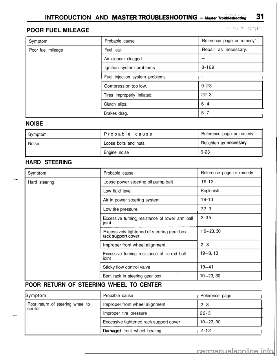
INTRODUCTION AND MASTER TROUBLESH’OOTING .- Master ~pAi&oOti~31POOR FUEL MILEAGE
../, *,, /S./..‘, _I, #_.a,‘.rr?
Symptom
Poor fuel mileageProbable cause
Fuel leak
Air cleaner clogged.Ignition system problems
Reference page or remedy”Repair as necessary.
-8-169
IFuel injection system problems.I-ICompression too low.9-23
Tires improperly inflated.22-3
Clutch slips.6-4
Brakes drag.5-7I
NOISE
Symptom
NoiseProbable cause
Loose bolts and nuts.
Engine noiseReference page or remedy
Retighten as necessary
9-23
’
HARD STEERING
Symptom
Hard steeringProbable causeLoose power steering oil pump belt
Low fluid levelAir in power steering system
Low tire pressure
Reference page or remedy19-12
Replenish19-13
22-3
Excessive turning resistance of lower arm ballExcessively tightened of steering gear box
IImproper front wheel alignment2-8
Excessive turning resistance of tie-rod ballioint2-35
1 i-23.30
19-8.10Sticky flow control valve
Bent rack in steering gear box‘.19-4119-23.30
POOR RETURN OF STEERING WHEEL TO CENTERSymptom
1Probable causeIReference pageI
Poor return of steering wheel tocenterImproper front wheel alignment
2-8
Improper tire pressure22-3
Excessive tightened rack support cover19-23.30
I-- ~~~Damaged front wheel bearingI2-12I
Page 32 of 1216
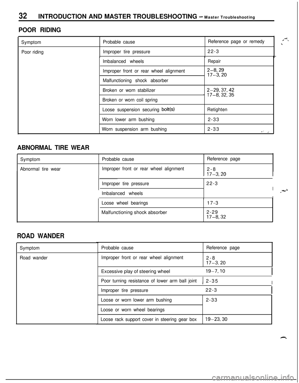
32INTRODUCTION AND MASTER TROUBLESHOOTING - Master Troubleshooting
POOR RIDING
Symptom
Poor ridingProbable causeReference page or remedy
Improper tire pressure22-3
lmbalanced wheels
Improper front or rear wheel alignment
Malfunctioning shock absorberRepair
2-8,2917-3.20
Broken or worn stabilizer
Broken or worn coil spring2-29,37,42_ 17-8,32,35
Loose suspension securing bolt(s)Retighten
Worn lower arm bushing2-33
Worn suspension arm bushing2-33Y,’ ,>’
1 17-3.20I
ABNORMAL TIRE WEAR
Symptom
Abnormal tire wearProbable causeReference page
Improper front or rear wheel alignment2-8
Improper tire pressure22-3
Ilmbalanced wheelsIILoose wheel bearingsMalfunctioning shock absorber17-3
2-29
17-8,32
ROAD WANDER
Symptom
Road wanderProbable cause
Improper front or rear wheel alignmentReference page2-8
17-3.20Excessive play of steering wheel
19-7.10
Poor turning resistance of lower arm ball joint1 2-35I
Improper tire pressure22-3
Loose or worn lower arm bushing2-33
Loose or worn wheel bearings
Loose rack support cover in steering gear box
19-23,30
/-=..\
Page 33 of 1216
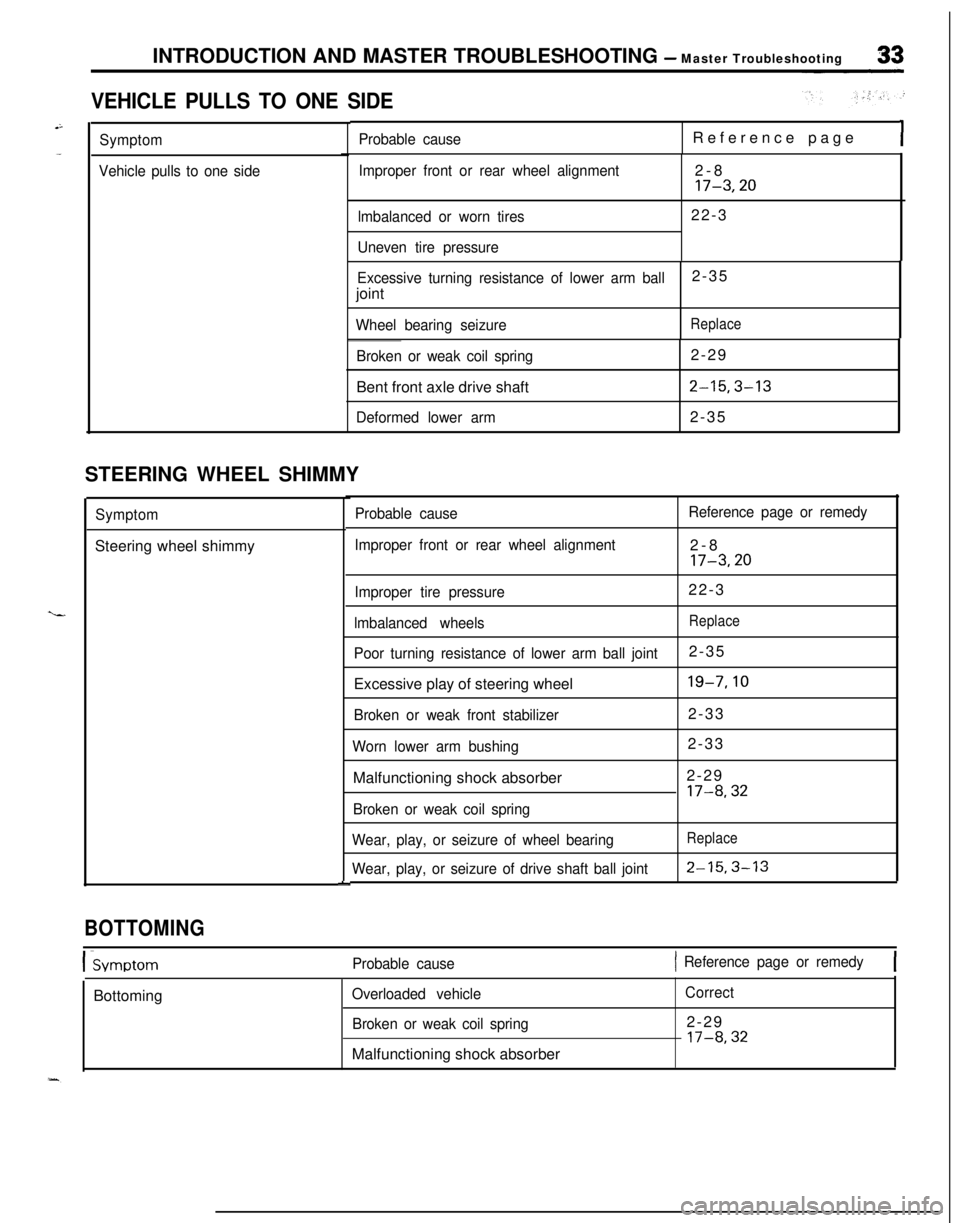
INTRODUCTION AND MASTER TROUBLESHOOTING - Master Troubleshooting
VEHICLE PULLS TO ONE SIDE
Symptom
Vehicle pulls to one sideProbable causeReference pageI
Improper front or rear wheel alignment
lmbalanced or worn tires
Uneven tire pressure2-817-3,2022-3
Excessive turning resistance of lower arm ball2-35
joint
Wheel bearing seizureReplace
Broken or weak coil spring2-29
Bent front axle drive shaft
2-15,3-13
Deformed lower arm2-35
STEERING WHEEL SHIMMY
SymptomSteering wheel shimmy
L
Probable cause
Improper front or rear wheel alignmentReference page or remedy2-8
17-3,20
Improper tire pressure22-3
lmbalanced wheelsReplace
Poor turning resistance of lower arm ball joint2-35
Excessive play of steering wheel
19-7,lO
Broken or weak front stabilizer2-33
Worn lower arm bushing2-33
Malfunctioning shock absorber2-29
17-8,32
Broken or weak coil spring
Wear, play, or seizure of wheel bearing
Wear, play, or seizure of drive shaft ball joint
Replace
2-15.3-13
BOTTOMING
I-SvmotomProbable cause1 Reference page or remedy[Bottoming
Overloaded vehicle
Broken or weak coil springMalfunctioning shock absorberCorrect2-29
l7-8,32
Page 49 of 1216
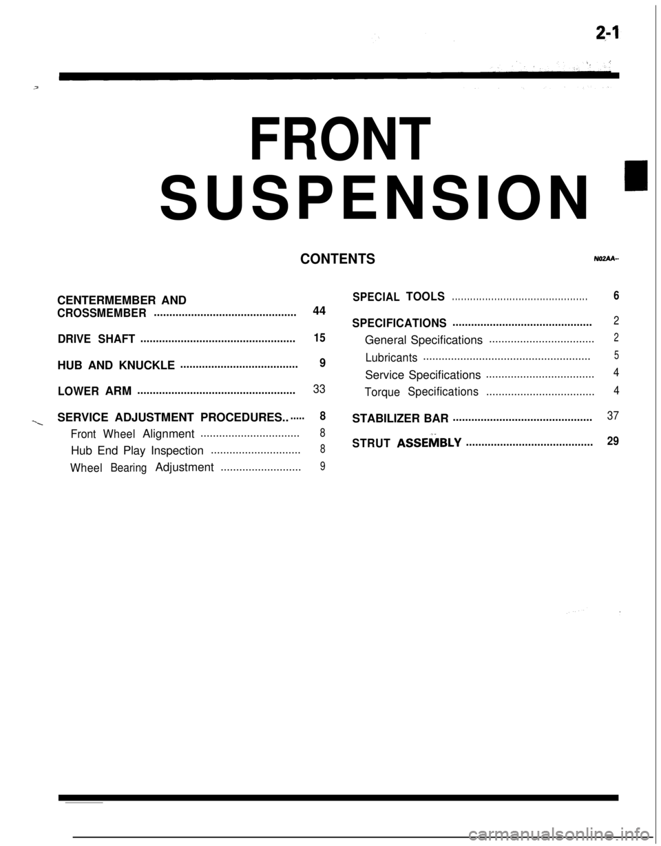
FRONTSUSPENSION
’
CONTENTSNOZAA-CENTERMEMBER AND
CROSSMEMBER..............................................44
DRIVESHAFT..................................................15HUB AND KNUCKLE
......................................9
LOWERARM
...................................................33
~SERVICE ADJUSTMENT PROCEDURES.......8
FrontWheelAlignment................................8Hub End Play Inspection
.............................8
WheelBearingAdjustment..........................9
SPECIALTOOLS. . . . . . . . . . . . . . . . . . . . . . . . . . . . . . . . . . . . . . . . . . . . .6
SPECIFICATIONS.............................................2General Specifications
..................................2
Lubricants......................................................5Service Specifications
...................................4
TorqueSpecifications...................................4STABILIZER BAR
.............................................37
STRUTASSEMBLY.........................................29
Page 54 of 1216
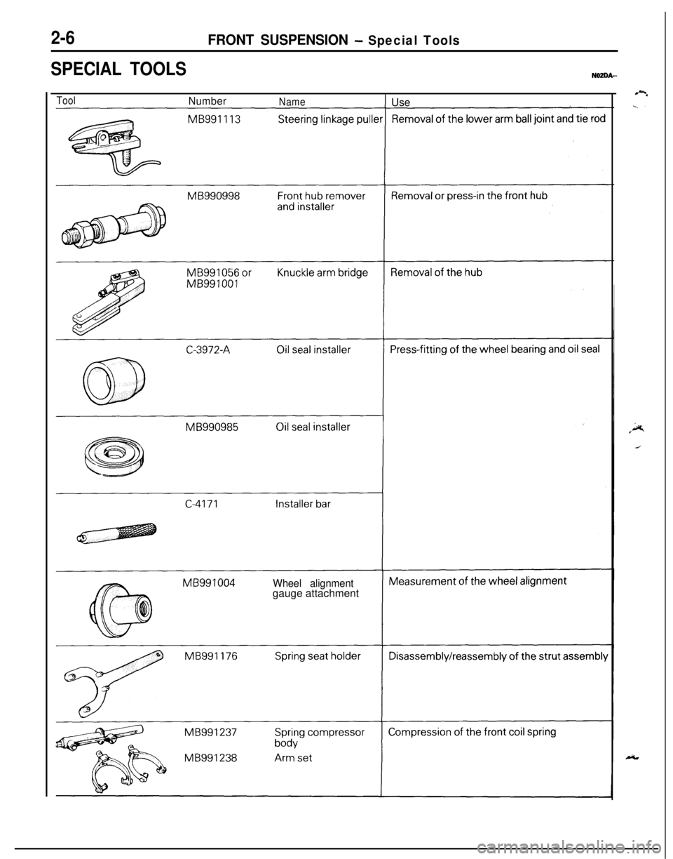
2-6FRONT SUSPENSION - Special Tools
SPECIAL TOOLS
ToolNumberNameI UseMB991004
Wheel alignmentgauge attachment
Page 56 of 1216
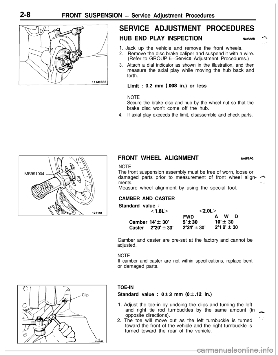
2-8FRONT SUSPENSION - Service Adjustment Procedures
SERVICE ADJUSTMENT PROCEDURES
HUB END PLAY INSPECTIONNO2FAAB --- ’
1. Jack up the vehicle and remove the front wheels.
2.Remove the disc brake caliper and suspend it with a wire.
(Refer to GROUP
5-Service Adjustment Procedures.)
3.Attach a dial indicator as shown in the illustration, and thenmeasure the axial play while moving the hub back and
forth.Limit
: 0.2 mm (.008 in.) or less
NOTE
Secure the brake disc and hub by the wheel nut so that thebrake disc won’t come off the hub.
4.If axial play exceeds the limit, disassemble and check parts.
FRONT WHEEL ALIGNMENTNOZFBAQ
NOTEThe front suspension assembly must be free of worn, loose or
damaged parts prior to measurement of front wheel align-
A
ments.--l
Measure wheel alignment by using the special tool.
CAMBER AND CASTER
Standard value
:
<1.8L><2.0L>
FWDAWD
Camber
14’+ 30’5’k3010’f 30
Caster250 + 30’2”24’ + 30’29 8’ f 30Camber and caster are pre-set at the factory and cannot be
adjusted.
NOTE
If camber and caster are not within specifications, replace bentor damaged parts.
TOE-INStandard value
:Of3 mm (Of.12 in.)
1. Adjust the toe-in by undoing the clips and turning the left
and right tie rod turnbuckles by the same amount (in
-opposite directions).
2. The toe will move out as the left turnbuckle is turned
- ,’toward the front of the vehicle and the right turnbuckle is
turned toward the rear of the vehicle.
Page 78 of 1216
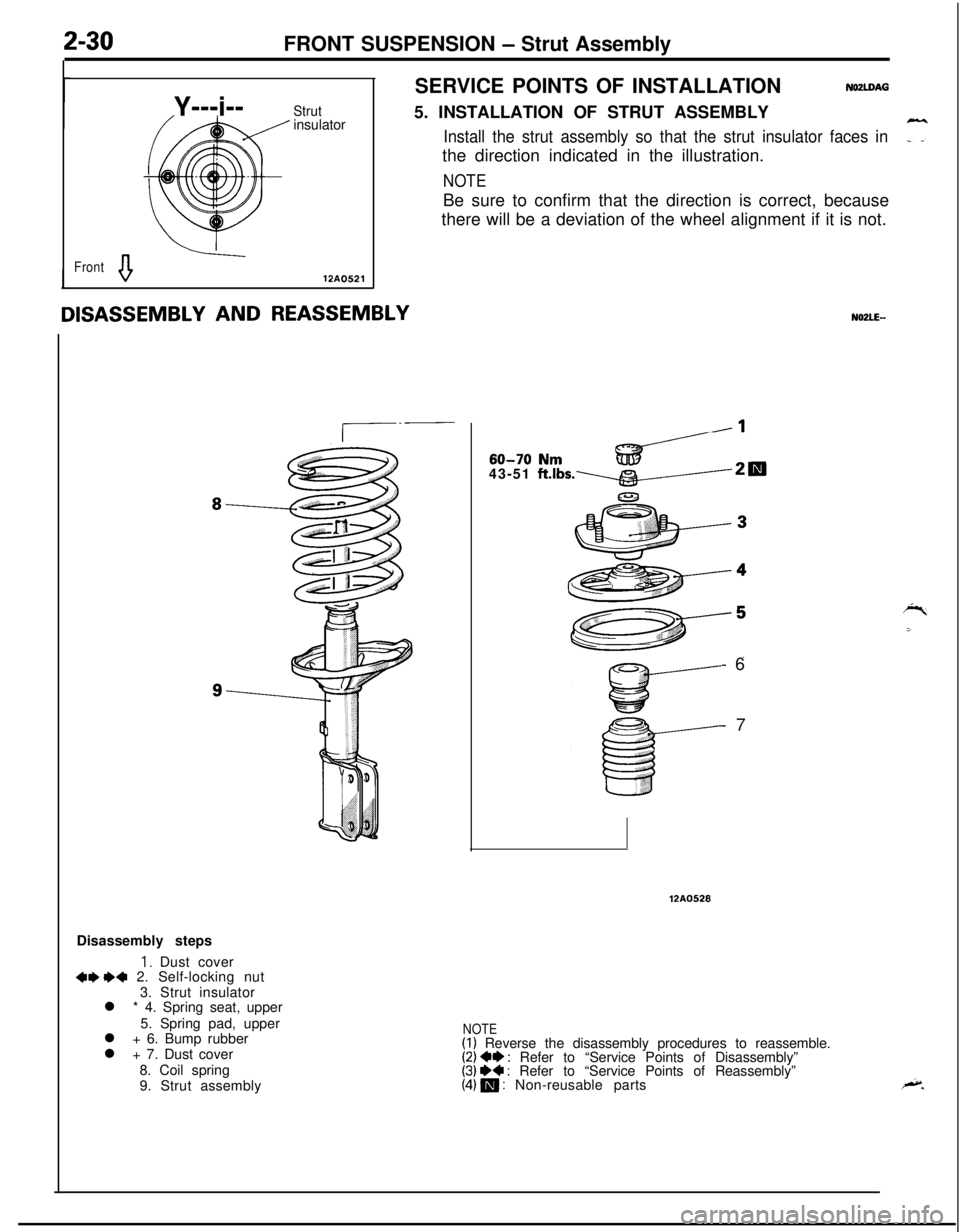
2-30FRONT SUSPENSION - Strut Assembly
Y---i--
Strutinsulator
Fronta12A0521SERVICE POINTS OF INSTALLATION
NOZLDAG5. INSTALLATION OF STRUT ASSEMBLY
Install the strut assembly so that the strut insulator faces in7the direction indicated in the illustration.
NOTEBe sure to confirm that the direction is correct, because
there will be a deviation of the wheel alignment if it is not.
Disassembly steps
I, Dust cover+e I)+ 2. Self-locking nut
3. Strut insulator
l * 4. Spring seat, upper
5. Spring pad, upper
l + 6. Bump rubber
l + 7. Dust cover
8. Coil spring
9. Strut assembly
N02LE-43-51
ft.lbs.~d/-2~60-70 Nm
-6
-7
12A0528
NOTE(I) Reverse the disassembly procedures to reassemble.(2) +e : Refer to “Service Points of Disassembly”(3) e+ : Refer to “Service Points of Reassembly”(4) m : Non-reusable parts
Page 444 of 1216
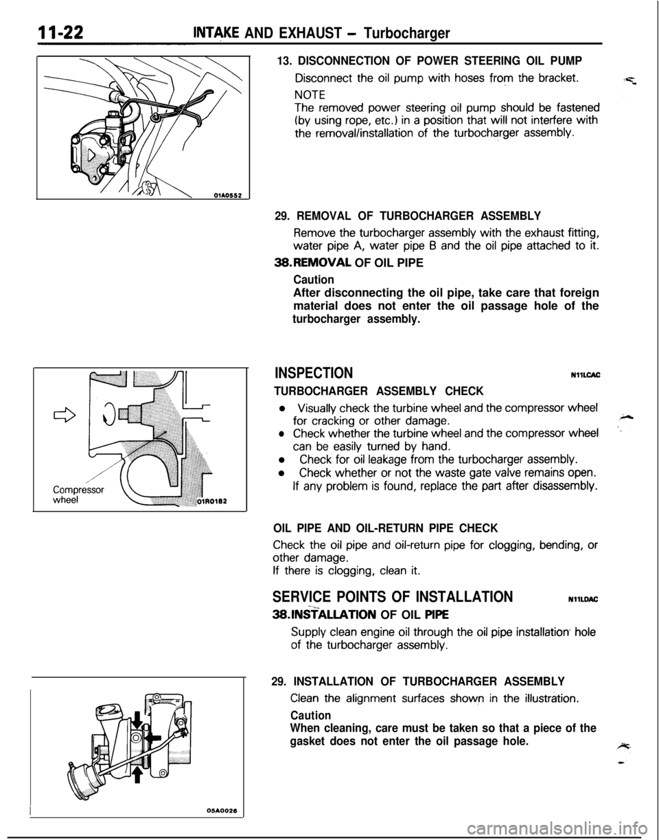
INTeKE AND EXHAUST - Turbocharger
13. DISCONNECTION OF POWER STEERING OIL PUMP
Disconnect the oil pump with hoses from the bracket.
NOTE
The removed power steering oil pump should be fastened
(by using rope, etc.) in a position that will not interfere with
the removal/installation of the turbocharger assembly.
I05AOO26
29. REMOVAL OF TURBOCHARGER ASSEMBLY
Remove the turbocharger assembly with the exhaust fitting,water
pipe A, water pipe 6 and the oil pipe attached to it.3B.REMOVAL OF OIL PIPE
CautionAfter disconnecting the oil pipe, take care that foreign
material does not enter the oil passage hole of the
turbocharger assembly.
INSPECTIONNllLCAC
TURBOCHARGER ASSEMBLY CHECKl
Visually check the turbine wheel and the compressor wheelfor
cracking or other damage.
lCheck whether the turbine wheel and the compressor wheel
can be easily turned by hand.l
Check for oil leakage from the turbocharger assembly.l
Check whether or not the waste gate valve remains open.
If any problem is found, replace the part after disassembly.
OIL PIPE AND OIL-RETURN PIPE CHECK
Check the oil pipe and oil-return pipe for clogging, bending, or
other damage.
If there is clogging, clean it.
SERVICE POINTS OF INSTALLATIONNllLDAC-x_3SlNSTALLATlON OF OIL PlPE
Supply clean engine oil through the oil pipe installation hole
of the turbocharger assembly.
29. INSTALLATION OF TURBOCHARGER ASSEMBLY
Clean the alignment surfaces shown in the illustration.
Caution
When cleaning, care must be taken so that a piece of the
gasket does not enter the oil passage hole.
Page 447 of 1216
INTAKE AND EXHAUST - Turbocharger~1xz5
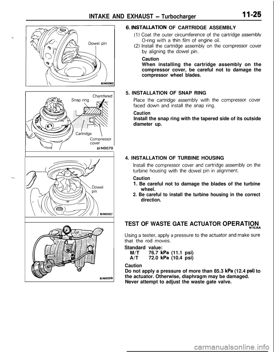
--=+I61 NO0706lN005E6.
INSTALLATIQN OF CARTRIDGE ASSEMBLY
(I1 Coat the outer circumference of the cartridge assembly
O-ring with a thin film of engine oil.
(29 Install the cartridge assembly on the compressor cover
by aligning the dowel pin.
CautionWhen installing the cartridge assembly on the
compressor cover, be careful not to damage the
compressor wheel blades.5. INSTALLATION OF SNAP RING
Place the cartridge assembly with the compressor cover
faced down and install the snap ring.
CautionInstall the snap ring with the tapered side of its outside
diameter up.4. INSTALLATION OF TURBINE HOUSING
Install the compressor cover and cartridge assembly on the
turbine housing with the dowel pin in alignment.
Caution
1. Be careful not to damage the blades of the turbine
wheel.
2. Be careful to install the turbine housing in the correct
direction.
TEST OF WASTE GATE ACTUATOR OPERATIONNllLlAA
Using a tester, apply a pressure to the actuator and make surethat the
rod moves.Standard value:
M/T76.7
kPa (11.1 psi)
A/T72.0
kPa (10.4 psi)
CautionDo not apply a pressure of more than 85.3
kPa (12.4 psi) to
the actuator. Otherwise, diaphragm may be damaged.
Never attempt to adjust the waste gate valve.
Page 611 of 1216
1 pq
,s I’
:
REAR
SUSPENSION
LATERAL ROD.................................................11
REAR AXLE HUB............................................14
REARSUSPENSIONASSEMBLY..................5
SERVICE ADJUSTMENT PROCEDURES.......3Rear Hub Rotary-Sliding Resistance
(Torque)Adjustment.....................................4Rear Wheel Alignment Inspection
...............3Wheel Bearing End Play Adjustment
..........3
SHOCKABSORBERASSEMBLY...................8
SPECIAL TOOL................................................3
SPECIFICATIONS.............................................2
GeneralSpecifications..................................2
ServiceSpecifications...................................2Torque Specifications
...................................2
TORSION AXLE AND ARM ASSEMBLY......12
TROUBLESHOOTING......................................3
REARSUSPENSIONASSEMBLY . . . . . . . . . . . . . . . . . .21
SHOCK ABSORBER ASSEMBLY...................32
SERVICE ADJUSTMENT PROCEDURES.......20Rear WheelAlignment
Inspection................20
SPECIAL TOOLS.............................................18
SPECIFICATIONS.............................................16
GeneralSpecifications..................................16
ServiceSpecifications...................................16LTorqueSpecifications...................................17
Lubricant.......................................................17
STABILIZER BAR. . . . . . . . . . . . . . . . . . . . . . . . . . . . . . . . . . . . . . . . . . . . .35
TRAILING ARM. . . . . . . . . . . . . . . . . . . . . . . . . . . . . . . . . . . . . . . . . . . . . . .28
TROUBLESHOOTING......................................19
UPPER AND LOWER ARM............................25
CONTENTSN17AA-