air condition MITSUBISHI ECLIPSE 1991 Service Manual
[x] Cancel search | Manufacturer: MITSUBISHI, Model Year: 1991, Model line: ECLIPSE, Model: MITSUBISHI ECLIPSE 1991Pages: 1216, PDF Size: 67.42 MB
Page 1176 of 1216
24-32HEATERS AND AIR CONDITIONING - Heater Unit
SERVICE POINTS OF REMOVAL6. REMOVAL OF
EVAPORATERRefer to GROUP 24-34.
NMISAO
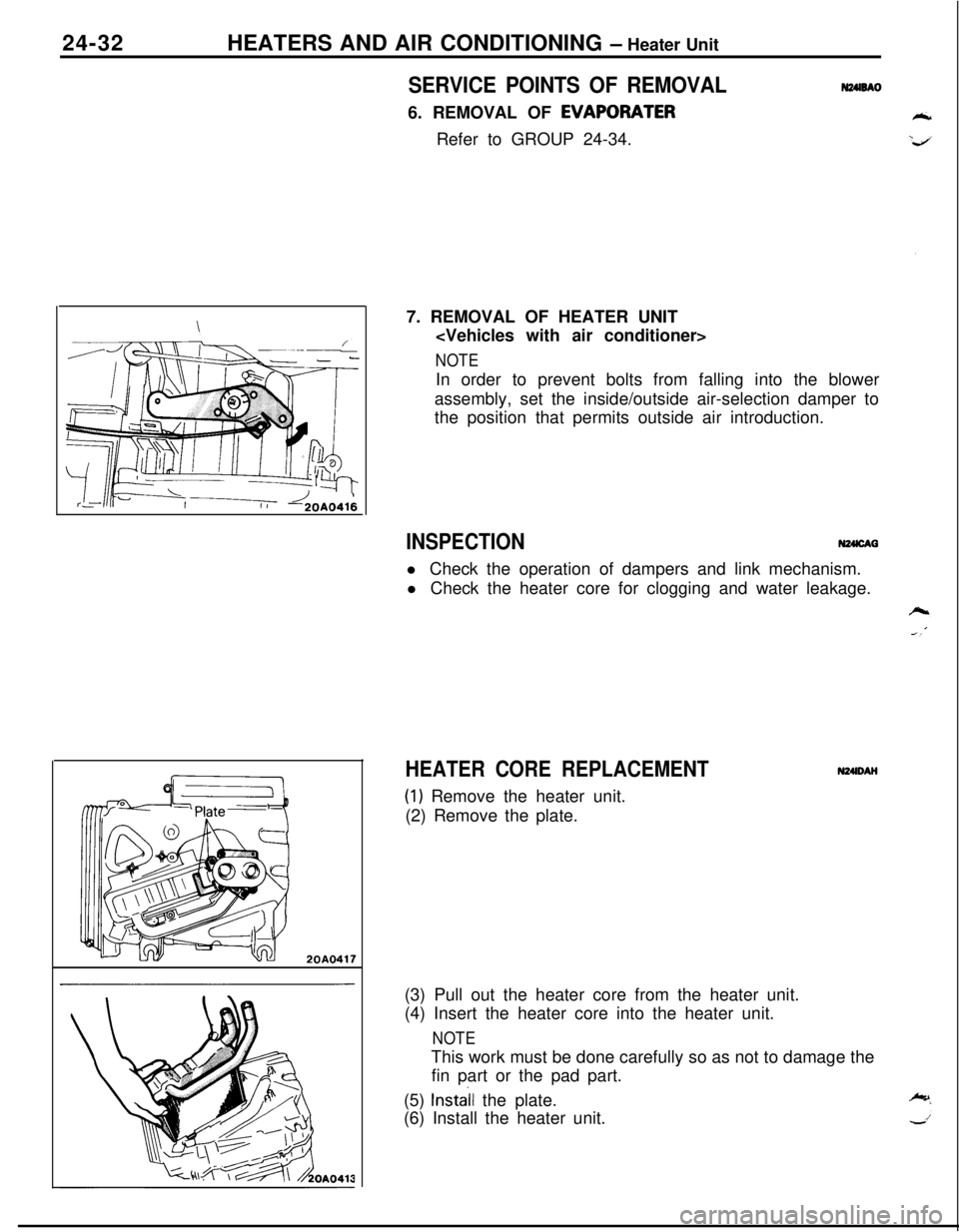
20A04177. REMOVAL OF HEATER UNIT
NOTEIn order to prevent bolts from falling into the blower
assembly, set the inside/outside air-selection damper to
the position that permits outside air introduction.
INSPECTIONN24lcAal Check the operation of dampers and link mechanism.
l Check the heater core for clogging and water leakage.
HEATER CORE REPLACEMENT
(1) Remove the heater unit.
(2) Remove the plate.N24lDAH
(3) Pull out the heater core from the heater unit.
(4) Insert the heater core into the heater unit.
NOTEThis work must be done carefully so as not to damage the
fin part or the pad part.
(5)
Install the plate.
(6) Install the heater unit.
Page 1177 of 1216
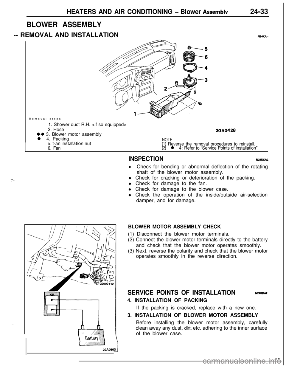
HEATERS AND AIR CONDITIONING - Blower Assemblv24-33Removal steps
1. Shower duct R.H.
2. Hose
+4 3. Blower motor assembly
l 4. Packing
--
. . . .
20A0428
5. t-an lnstallatlon nut6. Fan
NOTE(1) Reverse the removal procedures to reinstall.(2) l 4 : Refer to “Service Points of installation”.
BLOWER ASSEMBLY-- REMOVAL AND INSTALLATIONZOAO50
NUKA-
INSPECTIONN24KCAL
lCheck for bending or abnormal deflection of the rotating
shaft of the blower motor assembly.
l Check for cracking or deterioration of the packing.
l Check for damage to the fan.
l Check for damage to the blower case.
l Check the operation of the inside/outside air-selection
damper, and for damage.
BLOWER MOTOR ASSEMBLY CHECK
(1) Disconnect the blower motor terminals.
(2) Connect the blower motor terminals directly to the battery
and check that the blower motor operates smoothly.
(3) Next, reverse the polarity and check that the blower motor
operates smoothly in the reverse direction.
SERVICE POINTS OF INSTALLATIONNUKDAF4. INSTALLATION OF PACKING
If the packing is cracked, replace with a new one.
3. INSTALLATION OF BLOWER MOTOR ASSEMBLY
Before installing the blower motor assembly, carefully
clean away any dust, dirt, etc. adhering to the inner surface
of the blower case.
Page 1178 of 1216
24-34HEATERS AND AIR CONDITIONING - Evaporator
EVAPORATOR
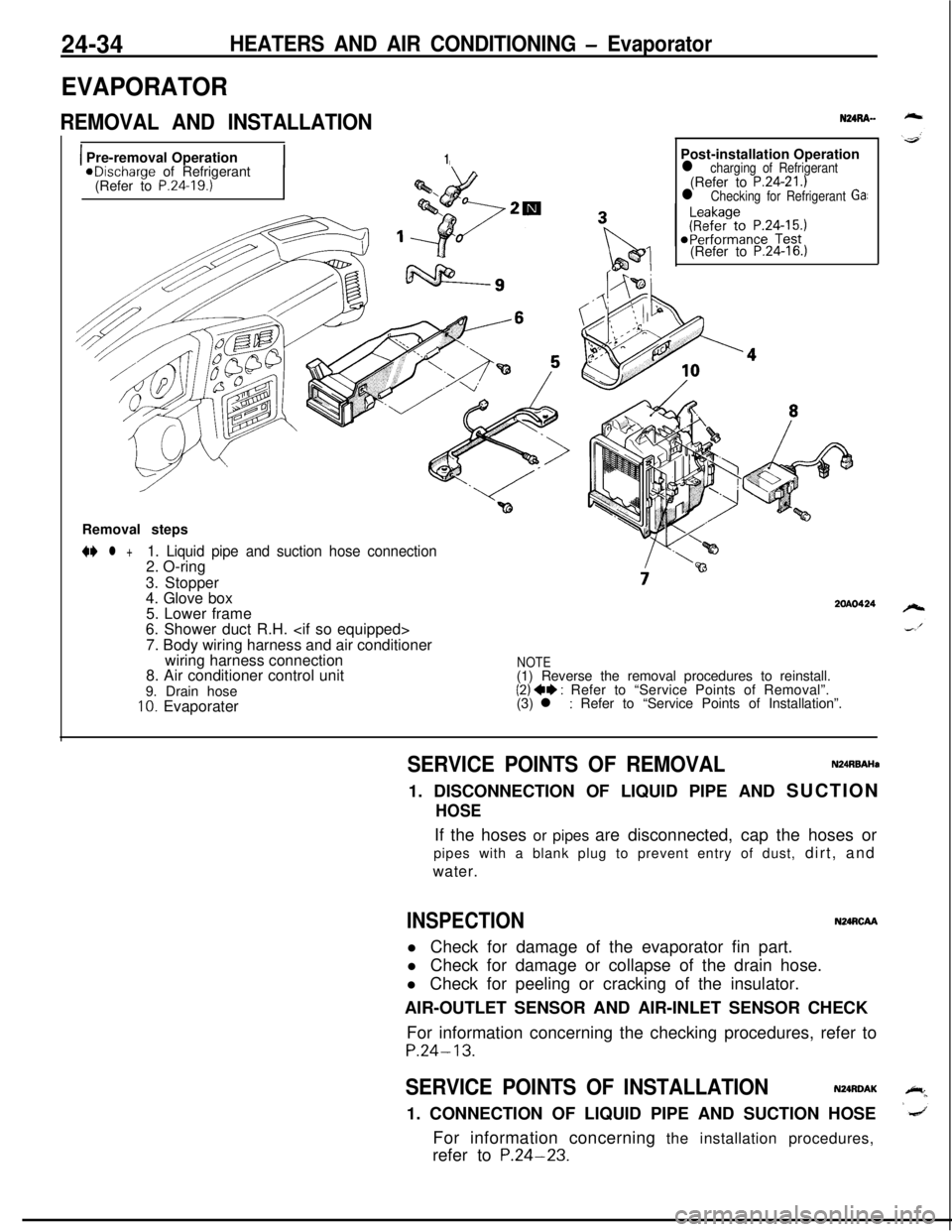
REMOVAL AND INSTALLATION
1 Pre-removal Operation1aDischarge of Refrigerant
(Refer to P.24.19.)Post-installation Operation
l charging of Refrigerant(Refer to P.24-21.)l Checking for Refrigerant Ga:(Refer to
P.24-16.)Removal steps
N l +1. Liquid pipe and suction hose connection2. O-ring
3. Stopper
4. Glove box
5. Lower frame
6. Shower duct R.H.
7. Body wiring harness and air conditioner
wiring harness connection
8. Air conditioner control unit
9. Drain hose
10. Evaporater
2OAO424
NOTE(1) Reverse the removal procedures to reinstall.
(2) ++ : Refer to “Service Points of Removal”.
(3) l : Refer to “Service Points of Installation”.
SERVICE POINTS OF REMOVALN24RBAHa1. DISCONNECTION OF LIQUID PIPE AND SUCTION
HOSEIf the hoses or pipes are disconnected, cap the hoses or
pipes with a blank plug to prevent entry of dust, dirt, and
water.
INSPECTIONN24RCAAl Check for damage of the evaporator fin part.
l Check for damage or collapse of the drain hose.
l Check for peeling or cracking of the insulator.
AIR-OUTLET SENSOR AND AIR-INLET SENSOR CHECK
For information concerning the checking procedures, refer to
P.24-13.
SERVICE POINTS OF INSTALLATIONN24RDAK1. CONNECTION OF LIQUID PIPE AND SUCTION HOSE
For information concerning the installation procedures,
refer to
P.24-23.
Page 1179 of 1216
HEATERS AND AIR CONDITIONING - Evaporator
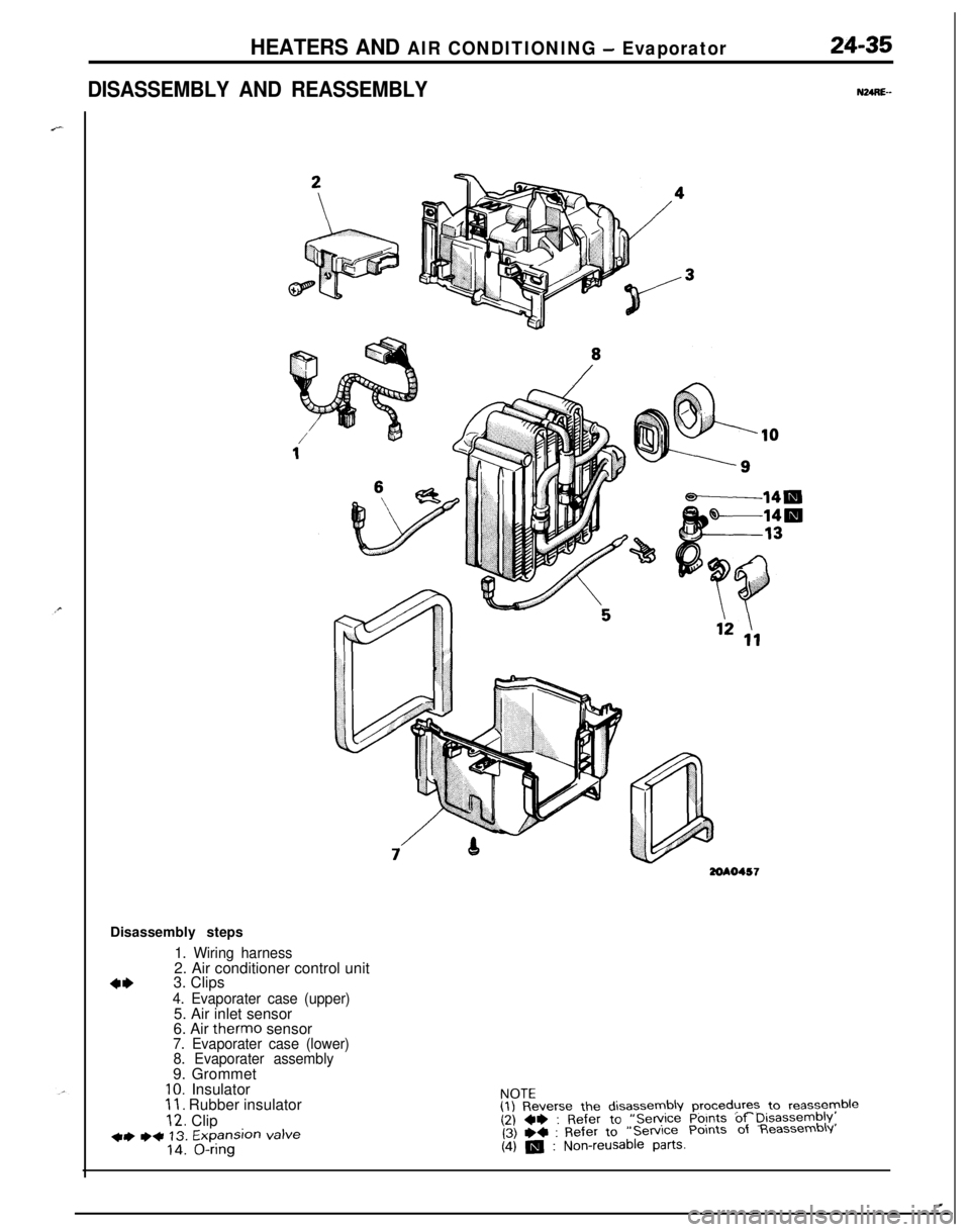
DISASSEMBLY AND REASSEMBLY
24-35
NURE--
3ZOAO457Disassembly steps
1. Wiring harness2. Air conditioner control unit
4*3. Clips4. Evaporater case (upper)5. Air inlet sensor
6. Air therm0 sensor
7. Evaporater case (lower)
8. Evaporater assembly9. Grommet
IO. Insulator11. Rubber insulator
12. Clip+) ++ 13. Expansion valve14. O-ringNOTE
(1) Reverse the disassembly procedures to reassyyble(2) ~~ : Refer to “Service Points of Disassembly,(3) +4 : Refer to“Service Points of Reassembly
(4) m : Non-reusable parts.
.
Page 1180 of 1216
24-36HEATERS AND AIR CONDITIONING - Evaporator
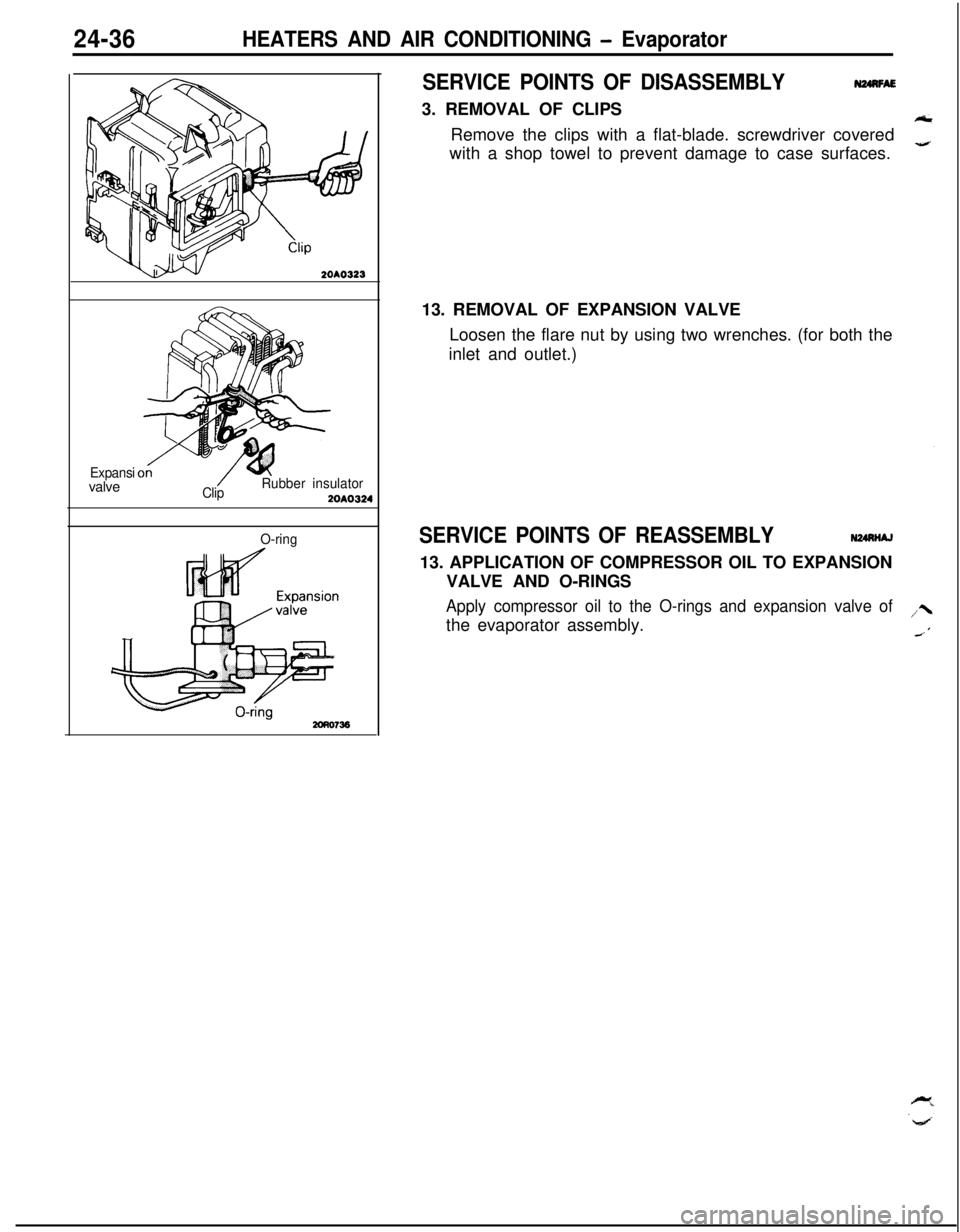
SERVICE POINTS OF DISASSEMBLY3. REMOVAL OF CLIPS
N24nFAERemove the clips with a flat-blade. screwdriver covered
with a shop towel to prevent damage to case surfaces.
2OAO323
Expansivalve
ClipRubber insulator2OAO324
O-ring13. REMOVAL OF EXPANSION VALVE
Loosen the flare nut by using two wrenches. (for both the
inlet and outlet.)SERVICE POINTS OF REASSEMBLYN24nNAJ13. APPLICATION OF COMPRESSOR OIL TO EXPANSION
VALVE AND O-RINGS
Apply compressor oil to the O-rings and expansion valve ofthe evaporator assembly.
Page 1181 of 1216
HEATERS AND AIR CONDITIONING - ComDressor24-37
COMPRESSOR <7.8L Engine>
em REMOVAL AND INSTALLATION
F)
*Removal of the distributor CapPost-installation Operation
@Charging of Refrigerant
(Refer to P.24-21.)@Adjustment of Compressor DriveBelt (Refer to P.24-23.)*Checking for Gas Leakage(Refer to P.24-15.)*Performance Test(Refer to P.24-16.)Removal steps of compressor drive belt and
tension pulley
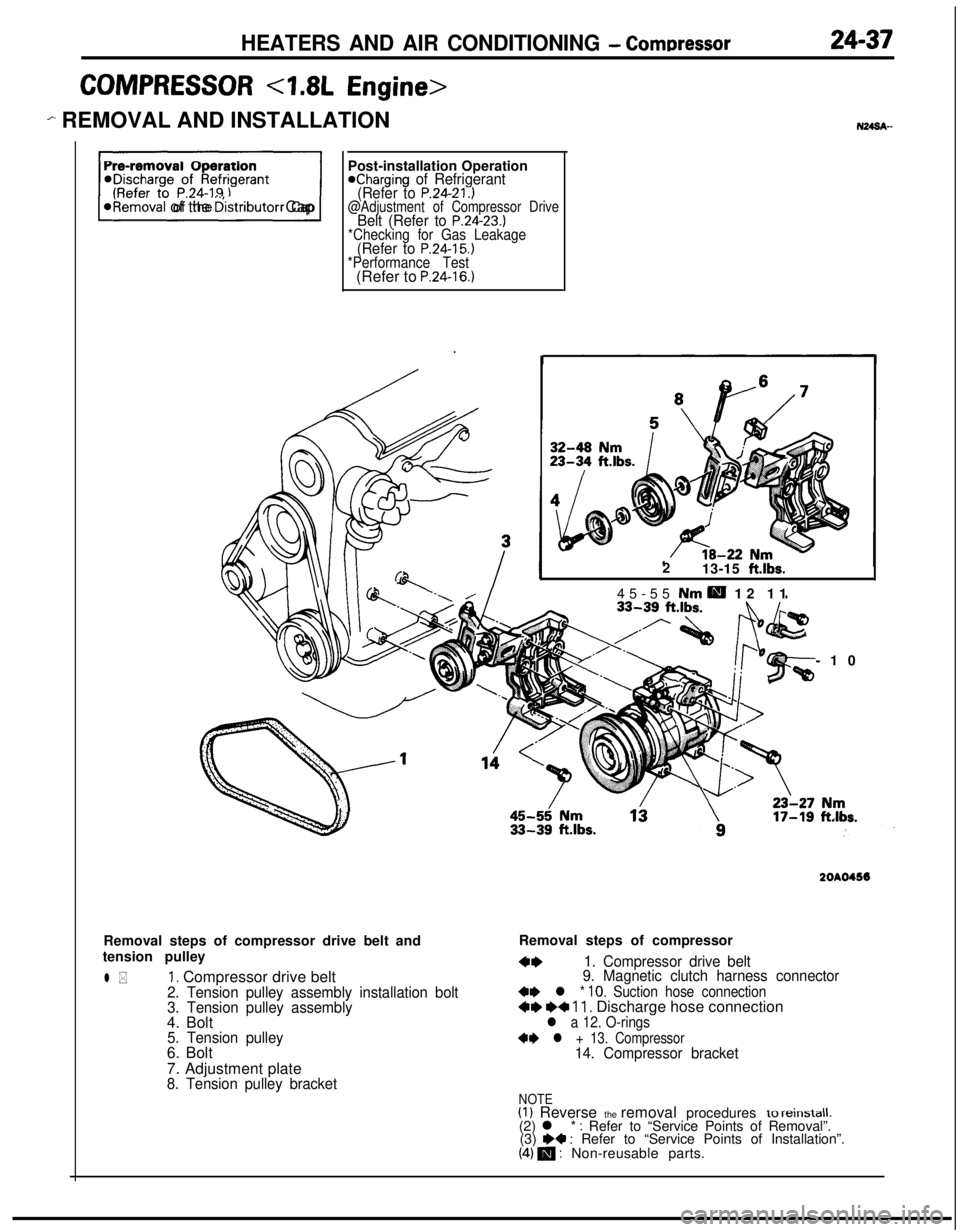
l *1, Compressor drive belt2. Tension pulley assembly installation bolt
3. Tension pulley assembly4. Bolt
5. Tension pulley6. Bolt
7. Adjustment plate
8. Tension pulley bracket2
13-15
ft.lbs.45-55 Nm
H 12 11
-10
2OAO456Removal steps of compressor
4*1. Compressor drive belt
9. Magnetic clutch harness connector
+e l * 10. Suction hose connection+e I)+ 11. Discharge hose connectionl a 12. O-rings
+* l + 13. Compressor14. Compressor bracket
NOTE(1) Reverse the removal procedures to reinstall.(2) l * : Refer to “Service Points of Removal”.
(3) W : Refer to “Service Points of Installation”.(4) m : Non-reusable parts.
Page 1182 of 1216
24-38HEATERS AND AIR CONDITIONING - Compressor
2OAOO87
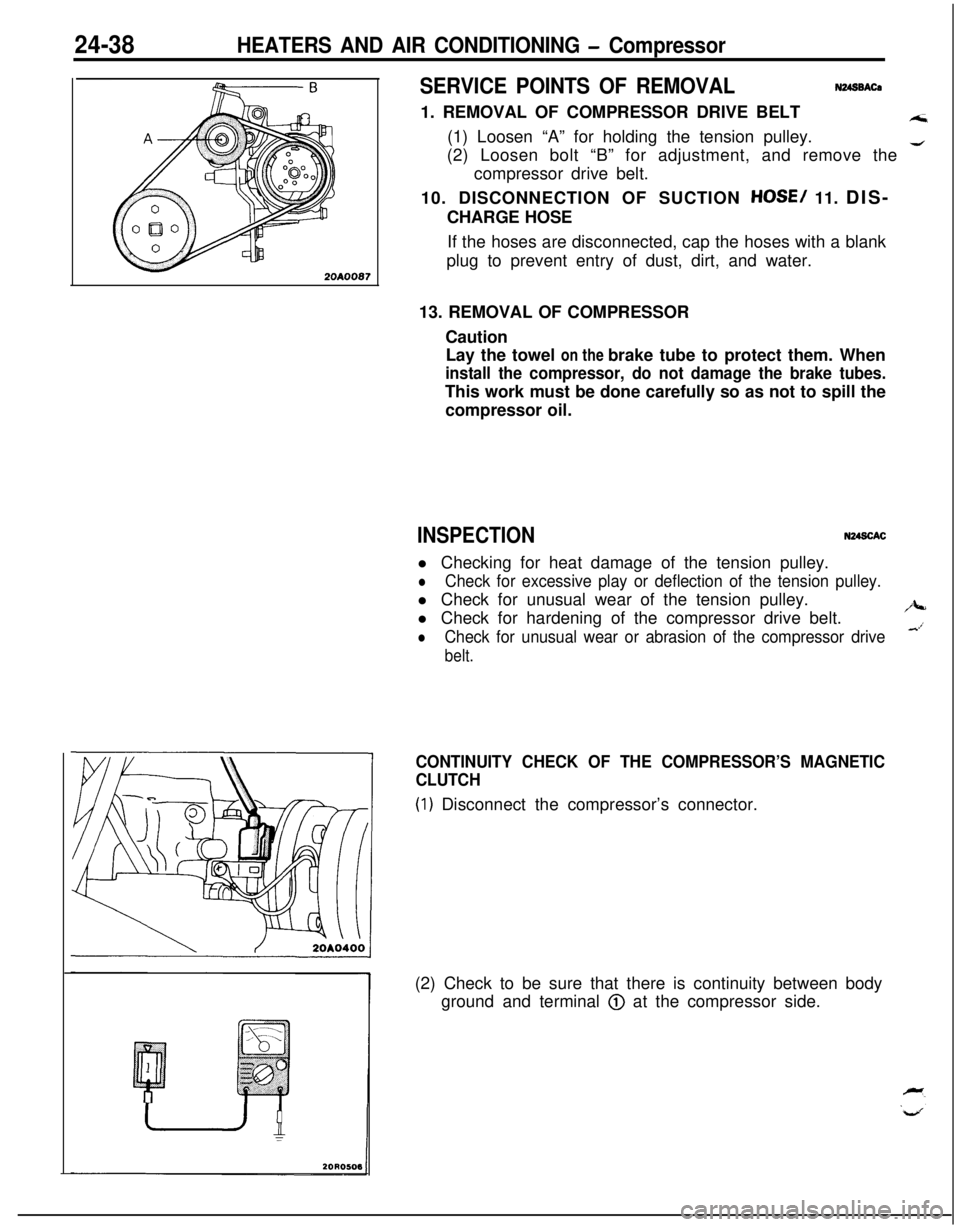
SERVICE POINTS OF REMOVALN248BACa1. REMOVAL OF COMPRESSOR DRIVE BELT
A;i(1) Loosen “A” for holding the tension pulley.
(2) Loosen bolt “B” for adjustment, and remove the
4compressor drive belt.
10. DISCONNECTION OF SUCTION
HOSE/ 11. DIS-
CHARGE HOSE
If the hoses are disconnected, cap the hoses with a blank
plug to prevent entry of dust, dirt, and water.
13. REMOVAL OF COMPRESSOR
Caution
Lay the towel on the brake tube to protect them. When
install the compressor, do not damage the brake tubes.This work must be done carefully so as not to spill the
compressor oil.
INSPECTIONN248CACl Checking for heat damage of the tension pulley.
lCheck for excessive play or deflection of the tension pulley.l Check for unusual wear of the tension pulley.
l Check for hardening of the compressor drive belt.
/J+-
lCheck for unusual wear or abrasion of the compressor drive&’
belt.
CONTINUITY CHECK OF THE COMPRESSOR’S MAGNETIC
CLUTCH
(1) Disconnect the compressor’s connector.
(2) Check to be sure that there is continuity between body
ground and terminal
@ at the compressor side.
Page 1183 of 1216
HEATERS AND AIR CONDITIONING - Compressor24-39
\/20A0400
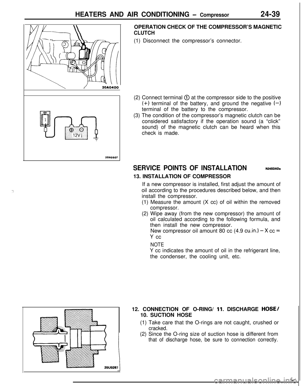
20R0507OPERATION CHECK OF THE COMPRESSOR’S MAGNETIC
CLUTCH(1) Disconnect the compressor’s connector.
(2) Connect terminal
@ at the compressor side to the positive(+) terminal of the battery, and ground the negative
(-)terminal of the battery to the compressor.
(3) The condition of the compressor’s magnetic clutch can be
considered satisfactory if the operation sound (a “click”
sound) of the magnetic clutch can be heard when this
check is made.
SERVICE POINTS OF INSTALLATIONN248DADa13. INSTALLATION OF COMPRESSOR
If a new compressor is installed, first adjust the amount of
oil according to the procedures described below, and then
install the compressor.
(1) Measure the amount (X cc) of oil within the removed
compressor.(2) Wipe away (from the new compressor) the amount of
oil calculated according to the following formula, and
then install the new compressor.
New compressor oil amount 80 cc (4.9
cu.in.) - X cc =
Y cc
NOTE
Y cc indicates the amount of oil in the refrigerant line,
the condenser, the cooling unit, etc.
12. CONNECTION OF O-RING/
11. DISCHARGE HOSE/
10. SUCTION HOSE
(1) Take care that the O-rings are not caught, crushed or
cracked.(2) Since the O-ring size of suction hose is different from
that of discharge hose, be sure to connection correctly.
1t
/
Page 1184 of 1216
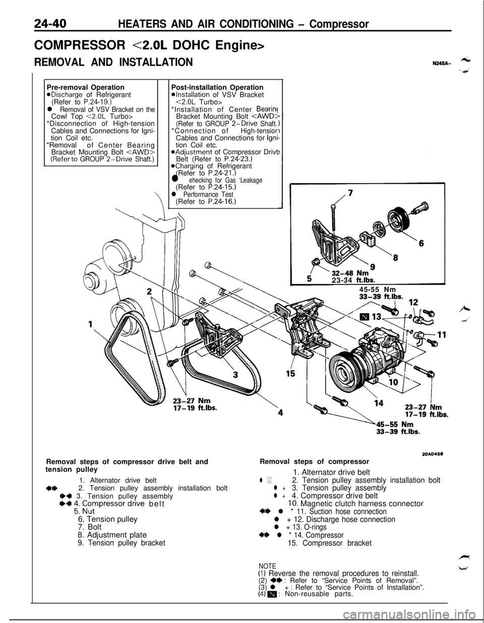
24-40HEATERS AND AIR CONDITIONING - CompressorCOMPRESSOR
<2.0L DOHC Engine>
REMOVAL AND INSTALLATIONPre-removal OperationaDischarge of Refrigerant
(Refer to
P.24-19.)l Removal of VSV Bracket on theCowl Top <2.0L Turbo>
*Disconnection of High-tension
Cables and Connections for Igni-
tion Coil etc.
*Removal
of Center Bearing
Bracket Mounting Bolt
*Installation of VSV Bracket<2.0L Turbo>
*Installation of Center
Bearin!Bracket Mounting Bolt
Belt (Refer to P.24-23.)Kharging of Refrigerant
(Refer to P.24-21.)l ehecking for Gas ‘Leakage(Refer to P.24-15.)l Performance Test(Refer to P.24-16.)
N24SA.-tension pulley
1. Alternator drive belt
4*2. Tension pulley assembly installation boltI)+ 3. Tension pulley assembly~~ 2: Grpressor dnve belt
6. Tension pulley
7. Bolt
8. Adjustment plate
9. Tension pulley bracket23-34
ft.lbs.45-55 Nm
33-39 ft.lbs.
2OAO4.58Removal steps of compressor drive belt andRemoval steps of compressor
1. Alternator drive belt
l *2. Tension pulley assembly installation boltl +3. Tension pulley assemblyl +4. Compressor drive belt10. Magnetic clutch harness connector+* l * 11. Suction hose connectionl + 12. Discharge hose connectionl + 13. O-rings
** l * 14. Compressor15. Compressor bracket
NOTE(I) Reverse the removal procedures to reinstall.(2) +e : Refer to “Service Points of Removal”.
(3) l + : Refer to “Service Points of Installation”.(4) m : Non-reusable parts.
Page 1185 of 1216
HEATERS AND AIR CONDITIONING - Compressor24-41
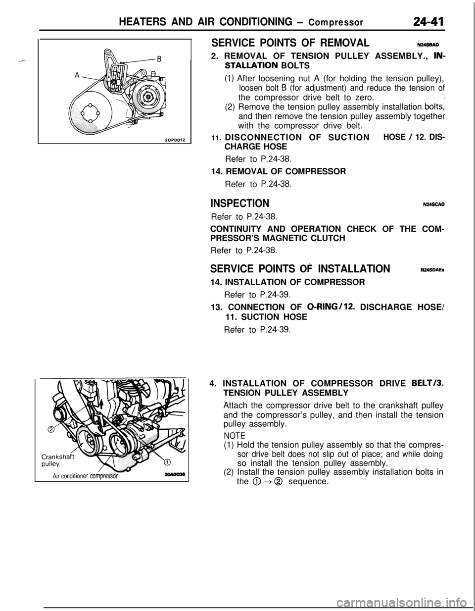
2OPOO12
Air condltlonercompressor
SERVICE POINTS OF REMOVALNusenD2. REMOVAL OF TENSION PULLEY ASSEMBLY.,
lN-
STALLATION BOLTS
(1) After loosening nut A (for holding the tension pulley),
loosen bolt B (for adjustment) and reduce the tension ofthe compressor drive belt to zero.
(2) Remove the tension pulley assembly installation
bolts:and then remove the tension pulley assembly together
with the compressor drive belt.
11. DISCONNECTION OF SUCTION
HOSE / 12. DIS-CHARGE HOSE
Refer to
P.24-38.14. REMOVAL OF COMPRESSOR
Refer to
P.24-38.
INSPECTIONN24SCADRefer to
P.24-38.CONTINUITY AND OPERATION CHECK OF THE COM-
PRESSOR’S MAGNETIC CLUTCH
Refer to
P.24-38.
SERVICE POINTS 03: INSTALLATIONN24SDAEa14. INSTALLATION OF COMPRESSOR
Refer to
P.24-39.13. CONNECTION OF
0-RING/lS. DISCHARGE HOSE/
11. SUCTION HOSE
Refer to
P.24-39.4. INSTALLATION OF COMPRESSOR DRIVE
BELT/3.TENSION PULLEY ASSEMBLY
Attach the compressor drive belt to the crankshaft pulley
and the compressor’s pulley, and then install the tension
pulley assembly.
NOTE(1) Hold the tension pulley assembly so that the compres-
sor drive belt does not slip out of place; and while doingso install the tension pulley assembly.
(2) Install the tension pulley assembly installation bolts in
the
@ + @ sequence.