air condition MITSUBISHI ECLIPSE 1991 Owners Manual
[x] Cancel search | Manufacturer: MITSUBISHI, Model Year: 1991, Model line: ECLIPSE, Model: MITSUBISHI ECLIPSE 1991Pages: 1216, PDF Size: 67.42 MB
Page 1166 of 1216
24-22 HEATERS AND AIR CONDITIONING - Service Adjustment Procedures(9) Charge through the suction side of the system by slowly
opening the suction manifold valve. Adjust the valve as
necessary so charging pressure does not exceed 345
kPa 6(50 psi). Maintain the temperature of the water in the pan w’
by adding warm water as necessary.
Note the weight of water added, to ensure accuracy when
determining amount of refrigerant added to system.
(lO)When specified refrigerant charge Max. 925
g (32 oz.) has
entered the system, close the gauge set manifold valves,
refrigerant manifold valves, and
reconnnect wiring. Each
can contains 397
g (14 oz.) of R-l 2. Use 2 l/2 cans.
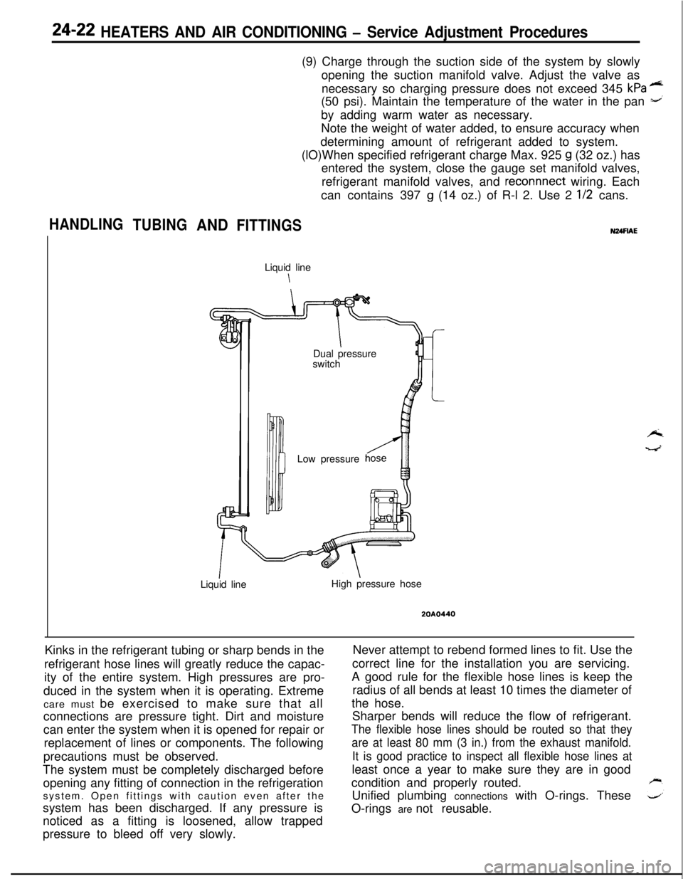
HANDLING
TUBINGANDFITTINGSLiquid line
\
IDual pressure
switch
Low pressure
Liquid lineHigh pressure hose
20A0440Kinks in the refrigerant tubing or sharp bends in the
refrigerant hose lines will greatly reduce the capac-
ity of the entire system. High pressures are pro-
duced in the system when it is operating. Extreme
care must be exercised to make sure that all
connections are pressure tight. Dirt and moisture
can enter the system when it is opened for repair or
replacement of lines or components. The following
precautions must be observed.
The system must be completely discharged before
opening any fitting of connection in the refrigeration
system. Open fittings with caution even after the
system has been discharged. If any pressure is
noticed as a fitting is loosened, allow trapped
pressure to bleed off very slowly.Never attempt to rebend formed lines to fit. Use the
correct line for the installation you are servicing.
A good rule for the flexible hose lines is keep the
radius of all bends at least 10 times the diameter of
the hose.
Sharper bends will reduce the flow of refrigerant.
The flexible hose lines should be routed so that they
are at least 80 mm (3 in.) from the exhaust manifold.
It is good practice to inspect all flexible hose lines atleast once a year to make sure they are in good
condition and properly routed.
Unified plumbing connections with O-rings. These
O-rings are not reusable.
Page 1167 of 1216
HEATERS AND AIR CONDITIONING - Service Adiustment Procedures 24-23
<
we2ouo2er
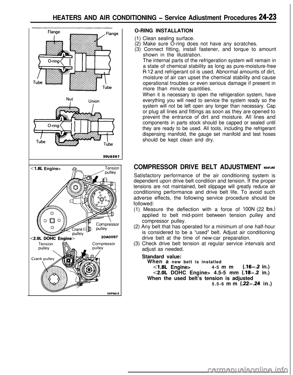
< 1.8L Engine>Tension/ wllevO-RING INSTALLATION
(1) Clean sealing surface.
(2) Make sure O-ring does not have any scratches.
(3) Connect fitting, install fastener, and torque to amount
shown in the illustration.
The internal parts of the refrigeration system will remain in
a state of chemical stability as long as pure-moisture-free
R-12 and refrigerant oil is used. Abnormal amounts of dirt,
moisture of air can upset the chemical stability and cause
operational troubles or even serious damage if present in
more than minute quantities.
When it is necessary to open the refrigeration system, have
everything you will need to service the system ready so the
system will not be left open any longer than necessary. Capor plug all lines and fittings as soon as they are opened to
prevent the entrance of dirt and moisture. All lines and
components in parts stock should be capped or sealed until
they are ready to be used. All tools, including the refrigerant
dispensing manifold, the gauge set manifold and test hosesshould be kept clean and dry.
COMPRESSOR DRIVE BELT ADJUSTMENT N24FJAESatisfactory performance of the air conditioning system is
dependent upon drive belt condition and tension. If the proper
tensions are not maintained, belt slippage will greatly reduce airconditioning performance and drive belt life. To avoid such
adverse effects, the following service procedure should be
followed:
(1) Measure the deflection with a force of
IOON (22 Ibs.)applied to belt mid-point between tension pulley and
compressor pulley.
(2) Any belt that has operated for a minimum of one half-hour
is considered to be a “used” belt. Adjust air conditioning
drive belt at the time of new-car preparation.
(3) Check drive belt tension at regular service intervals and
adjust as needed.
Standard value:
When a new belt is installed<1.8L Engine>4-5 mm
(.16-.2 in.)
<2.0L DOHC Engine> 4.5-5 mm (.18-.2 in.)
When the used belt’s tension is adjusted
5.5-6 mm
(.22-.24 in.)
Page 1168 of 1216
24-24 HEATERS AND AIR CONDITIONING - Service Adjustment Procedures
COMPRESSOR NOISENUFIABWhen investigating an air conditioning related noise, you must
first know the conditions when the noise occurs. These
conditions are: weather, vehicle speed, in gear or neutral,
engine temperature or any other special conditions.
Noises that develop during air conditioning operation can oftenbe misleading. For example: what sounds like a failed front
bearing or connecting rod, may be caused by loose bolts, nuts,mounting brackets, or a loose clutch assembly. Verify acces-
sory drive belt tension (power steering, or alternator).
Improper accessory drive belt tension can cause a misleading
noise when the compressor is engaged and little or no noise
when the compressor is disengaged.
Drive belts are speed sensitive. That is, at different engine
speeds, and depending upon belt tension, belts can develop
unusual noises that are often mistaken for mechanical prob-
lems within the compressor.
Adjustment Procedures
(1) Select a quiet area for testing. Duplicate conditions as
much as possible. Switch compressor on and off several
times to clearly identify compressor noise.
To duplicate high ambient conditions (high head pressure),restrict air flow through condenser. Install manifold gauge
set to make sure discharge pressure doesn’t exceed 2,070
kPa (300 psi).
(2) Tighten all compressor mounting bolts, clutch mounting
bolt, and compressor drive belt. Check to assure clutch coilis tight (no rotation or wobble).
(3) Check refrigerant hoses for rubbing or interference that cancause unusual noises.
(4) Check refrigerant charge (See “Charging the System”).
(5) Recheck compressor noise as in Step 1.
(6) If noise still exists, loosen compressor mounting bolts and
retorque. Repeat Step 1.
(7) If noise continues, replace compressor and repeat Step 1.
Condenser fan motor relay,
Magnet clutch
relay, Blower
motor High
relayHeater relayML0312
16W908
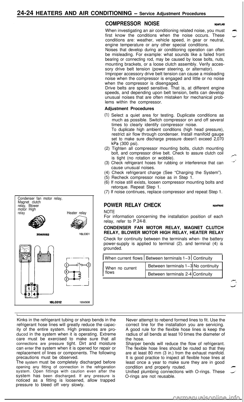
POWER RELAY CHECKNUFNAE
NOTEFor information concerning the installation position of each
relay, refer to
P.24-8.CONDENSER FAN MOTOR RELAY, MAGNET CLUTCH
RELAY, BLOWER MOTOR HIGH RELAY, HEATER RELAY
Check for continuity between the terminals when- the battery
power-supply is applied to terminal (2). and terminal (4) is
grounded.
1 When current flows 1 Between terminals l-3 1 Continuity1
I
When no currentBetween terminals l-3 No continuity
flowsBetween terminals 2-4 Continuity
IKinks in the refrigerant tubing or sharp bends in the
Never attempt to rebend formed lines to fit. Use the
refrigerant hose lines will greatly reduce the
capac-correct line for the installation you are servicing.
ity of the entire system. High pressures are
pro-A good rule for the flexible hose lines is keep the
duced in the system when it is operating. Extreme
radius of all bends at least 10 times the diameter of
care must be exercised to make sure that all
the hose.
connections are pressure tight. Dirt and moisture
Sharper bends will reduce the flow of refrigerant.
can enter the system when it is opened for repair or
The flexible hose lines should be routed so that theyreplacement of lines or components. The following
are at least 80 mm (3 in.) from the exhaust manifold.precautions must be observed.
It is good practice to inspect all flexible hose lines atThe system must be completely discharged before
least once a year to make sure they are in good
opening any fitting of connection in the refrigeration
condition and properly routed.
Fsystem. Open fittings with caution even after the
Unified plumbing connections with O-rings. These
4’system has been discharged. If any pressure is
noticed as a fitting is loosened, allow trappedO-rings are not reusable.
pressure to bleed off very slowly.
Page 1169 of 1216
HEATERS AND AIR CONDITIONING - Service Adjustment Procedures 24-25
16A1077
20AO499
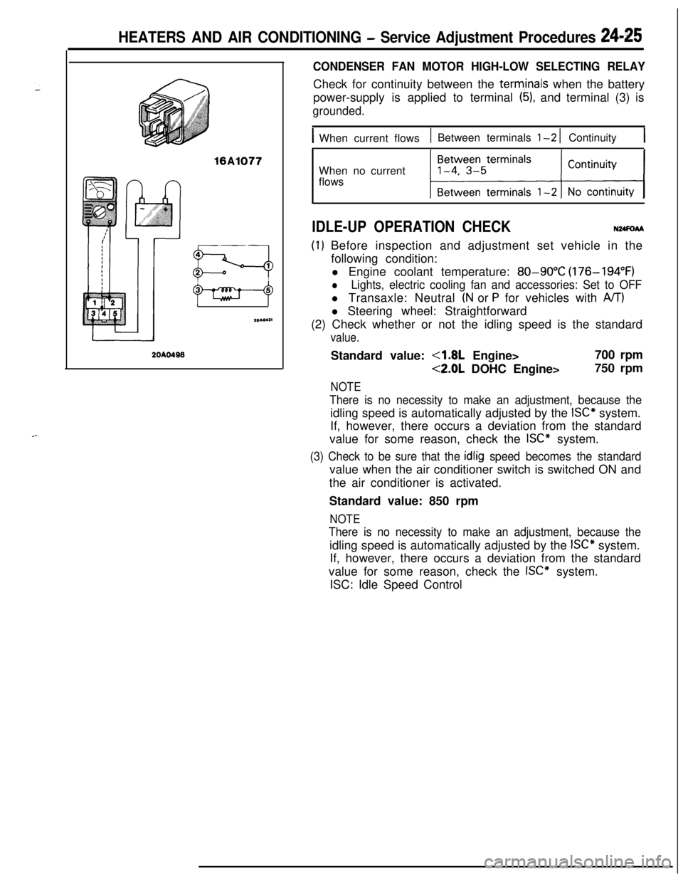
CONDENSER FAN MOTOR HIGH-LOW SELECTING RELAYCheck for continuity between the
term,inals when the battery
power-supply is applied to terminal
(5), and terminal (3) is
grounded.
IWhen current flows1 Between terminals l-2 1 Continuity1When no current
flows
IDLE-UP OPERATION CHECKN24FoAA
(I) Before inspection and adjustment set vehicle in the
following condition:
l Engine coolant temperature:
80-90°C (176-194°F)
lLights, electric cooling fan and accessories: Set to OFFl Transaxle: Neutral
(N or P for vehicles with A/T)l Steering wheel: Straightforward
(2) Check whether or not the idling speed is the standard
value.Standard value:
4.8L Engine>700 rpm
<2.0L DOHC Engine>750 rpm
NOTE
There is no necessity to make an adjustment, because theidling speed is automatically adjusted by the
ISC” system.
If, however, there occurs a deviation from the standard
value for some reason, check the
ISC” system.
(3) Check to be sure that the idlig speed becomes the standardvalue when the air conditioner switch is switched ON and
the air conditioner is activated.
Standard value: 850 rpm
NOTE
There is no necessity to make an adjustment, because theidling speed is automatically adjusted by the
ISC” system.
If, however, there occurs a deviation from the standard
value for some reason, check the
ISC” system.
ISC: Idle Speed Control
Page 1170 of 1216
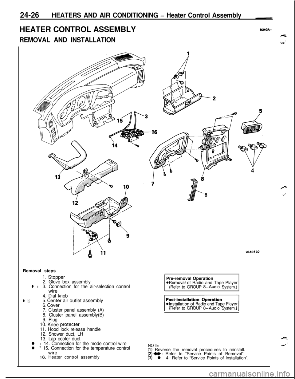
24-26HEATERS AND AIR CONDITIONING - Heater Control AssemblyHEATER CONTROL ASSEMBLY
REMOVAL AND INSTALLATIONRemoval steps
1. Stopper2. Glove box assemblyl +3. Connection for the air-selection controlwire
4. Dial knob
l *;: CI.Z;Er air outlet assembly
7. Cluster panel assembly (A)
8. Cluster panel assembly(B)
9. Plug
10. Knee protecter11. Hood lock release handle
12. Shower duct, LH
13. Lap cooler duct
l + 14. Connection for the mode control wire
l * 15. Connection for the temperature controlwire
16. Heater control assembly4
6
2OAO430Pre-removal Operation
@Removal of Radio and Tape Player(Refer to GROUP 8-Audio System.)
(Refer to GROUP
8-Audio System.)
NOTE(1) Reverse the removal procedures to reinstall.(2) 4e : Refer to “Service Points of Removal”.(3) l 4 : Refer to “Service Points of Installation”.
Page 1171 of 1216
HEATERS AND AIR CONDITIONING - Heater Control Assembly24-27
lQA0274
20A0408
SERVICE POINTS OF REMOVALN24GBAL
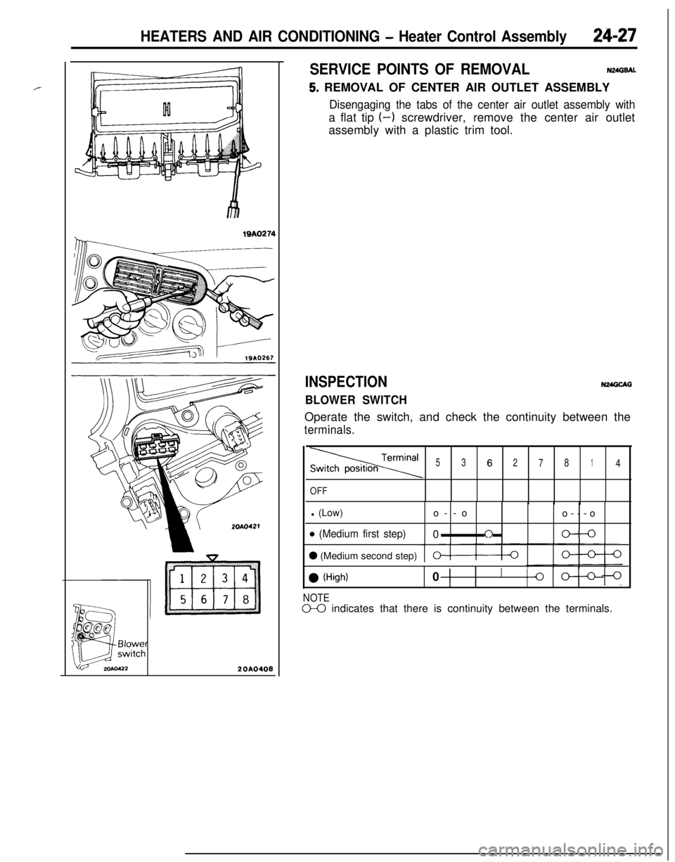
5. REMOVAL OF CENTER AIR OUTLET ASSEMBLY
Disengaging the tabs of the center air outlet assembly witha flat tip (-1 screwdriver, remove the center air outlet
assembly with a plastic trim tool.
INSPECTION
BLOWER SWITCHN24GCAG
Operate the switch, and check the continuity between the
terminals.
Termina’53627814
OFFl (Low)
o--o
o---o
o (Medium first step)0f-le-0
0 (Medium second step)0-0
0 (High)0 1I
Ilo oln
NOTED0 indicates that there is continuity between the terminals.
Page 1172 of 1216
24-28HEATERS AND AIR CONDITIONING - Heater Control Assembly
II
IT20AO409
SERVICE POINTS OF INSTALLATIONN24GOAO
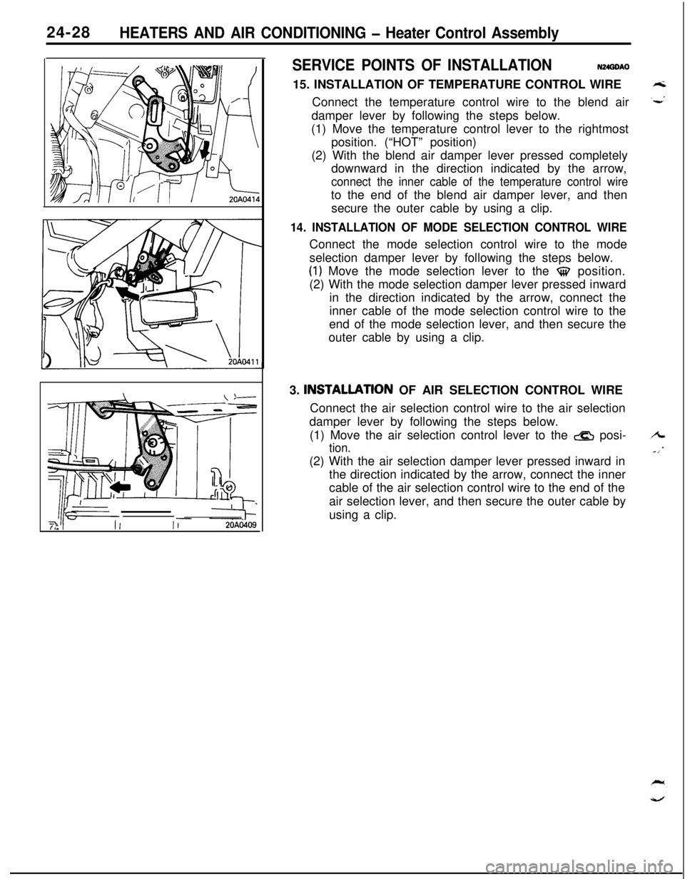
15. INSTALLATION OF TEMPERATURE CONTROL WIRE
Connect the temperature control wire to the blend air
damper lever by following the steps below.
(1) Move the temperature control lever to the rightmost
position. (“HOT” position)
(2) With the blend air damper lever pressed completely
downward in the direction indicated by the arrow,
connect the inner cable of the temperature control wireto the end of the blend air damper lever, and then
secure the outer cable by using a clip.
14. INSTALLATION OF MODE SELECTION CONTROL WIREConnect the mode selection control wire to the mode
selection damper lever by following the steps below.
(1) Move the mode selection lever to the $$ position.
(2) With the mode selection damper lever pressed inward
in the direction indicated by the arrow, connect the
inner cable of the mode selection control wire to the
end of the mode selection lever, and then secure the
outer cable by using a clip.
3. INSTALLATlON OF AIR SELECTION CONTROL WIRE
Connect the air selection control wire to the air selection
damper lever by following the steps below.
(1) Move the air selection control lever to the
& posi-
tion.(2) With the air selection damper lever pressed inward in
the direction indicated by the arrow, connect the inner
cable of the air selection control wire to the end of the
air selection lever, and then secure the outer cable by
using a clip.
Page 1173 of 1216
HEATERS AND AIR CONDITIONING - Resistor
RESISTOR
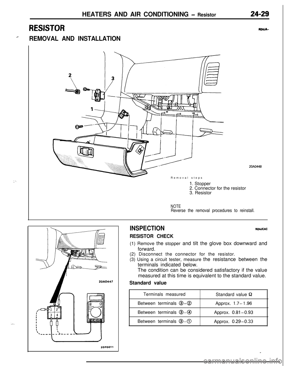
rREMOVAL AND INSTALLATIONRemoval steps
20A0447
1. Stopper
2. Connector for the resistor
3. Resistor
NOTEReverse the removal procedures to reinstall.
INSPECTION
RESISTOR CHECK
N2UCAC(1) Remove the stopper and tilt the glove box downward and
forward.(2) Disconnect the connector for the resistor.
(3) Using a circuit tester, measure the resistance between the
terminals indicated below.
The condition can be considered satisfactory if the value
measured at this time is equivalent to the standard value.
Standard value
Terminals measuredStandard value PBetween terminals
O-0Approx. 1.7- ‘I .96Between terminals @-@I
Approx.
0.81-0.93Between terminals
0-0Approx. 0.29-0.33
20A0448
Page 1174 of 1216
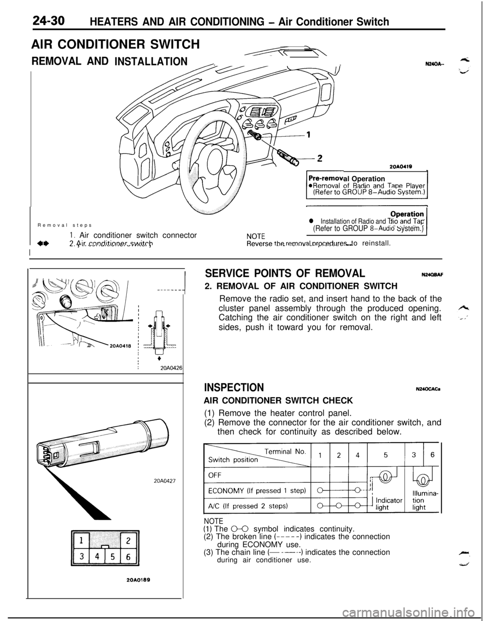
24-30HEATERS AND AIR CONDITIONING - Air Conditioner SwitchAIR CONDITIONER SWITCH
REMOVAL AND--N24OA..INSTALLATION
-2OAO419al Operationof
R;tdio and TanePlaver@Removal -..--._ _.-.-, -Removal steps
I. Air conditioner switch connectorCL7 Air rnnditinner switch
l Installation of Radio and Tape Player(Refer to GROUP 8-Audio System.)
NOTEOperation /Reverse
removal orocedures to reinstall.
I
77-. , .,a -.,a ,-,..-,.-. -.....,. ,.._._.__ _..- .-...-.-.r----- --
-----A
20A0427
20A0199
SERVICE POINTS OF REMOVALN24QBAF2. REMOVAL OF AIR CONDITIONER SWITCH
Remove the radio set, and insert hand to the back of the
cluster panel assembly through the produced opening.
Catching the air conditioner switch on the right and left
sides, push it toward you for removal.
INSPECTIONN24OCACaAIR CONDITIONER SWITCH CHECK
(1) Remove the heater control panel.
(2) Remove the connector for the air conditioner switch, and
then check for continuity as described below.
NOTE(1) The 0-0 symbol indicates continuity.
(2) The broken line (-----) indicates the connection
during ECONOMY use.
(3) The chain line
(- -----) indicates the connection
during air conditioner use.
Page 1175 of 1216
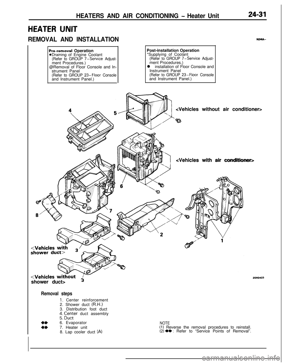
HEATERS AND AIR CONDITIONING - Heater Unit24-31
HEATER UNIT
REMOVAL AND INSTALLATIONN24m-
Pre-removal OperationeDraining of Engine Coolant(Refer to GROUP 7-Service Adjust-ment Procedures.)
@Removal of Floor Console and In-
strument Panel
(Refer to GROUP 23-Floor Consoleand Instrument Panel.)Post-installation Operation
*Supplying of Coolant
(Refer to GROUP 7-Service Adjust-ment Procedures.)
l installation of Floor Console and
Instrument Panel
(Refer to GROUP 23-Floor Consoleand Instrument Panel.)
shower duct>
Jshower duct>
Removal steps
1. Center reinforcement
2. Shower duct (R.H.)
3. Distribution foot duct
;: ;Z;;er duct assembly
:z6. Evaporator
7. Heater unit
8. Lap cooler duct (A)
NOTE(1) Reverse the removal procedures to reinstall.(2) 4* : Refer to “Service Points of Removal”.