air condition MITSUBISHI ECLIPSE 1991 Repair Manual
[x] Cancel search | Manufacturer: MITSUBISHI, Model Year: 1991, Model line: ECLIPSE, Model: MITSUBISHI ECLIPSE 1991Pages: 1216, PDF Size: 67.42 MB
Page 565 of 1216
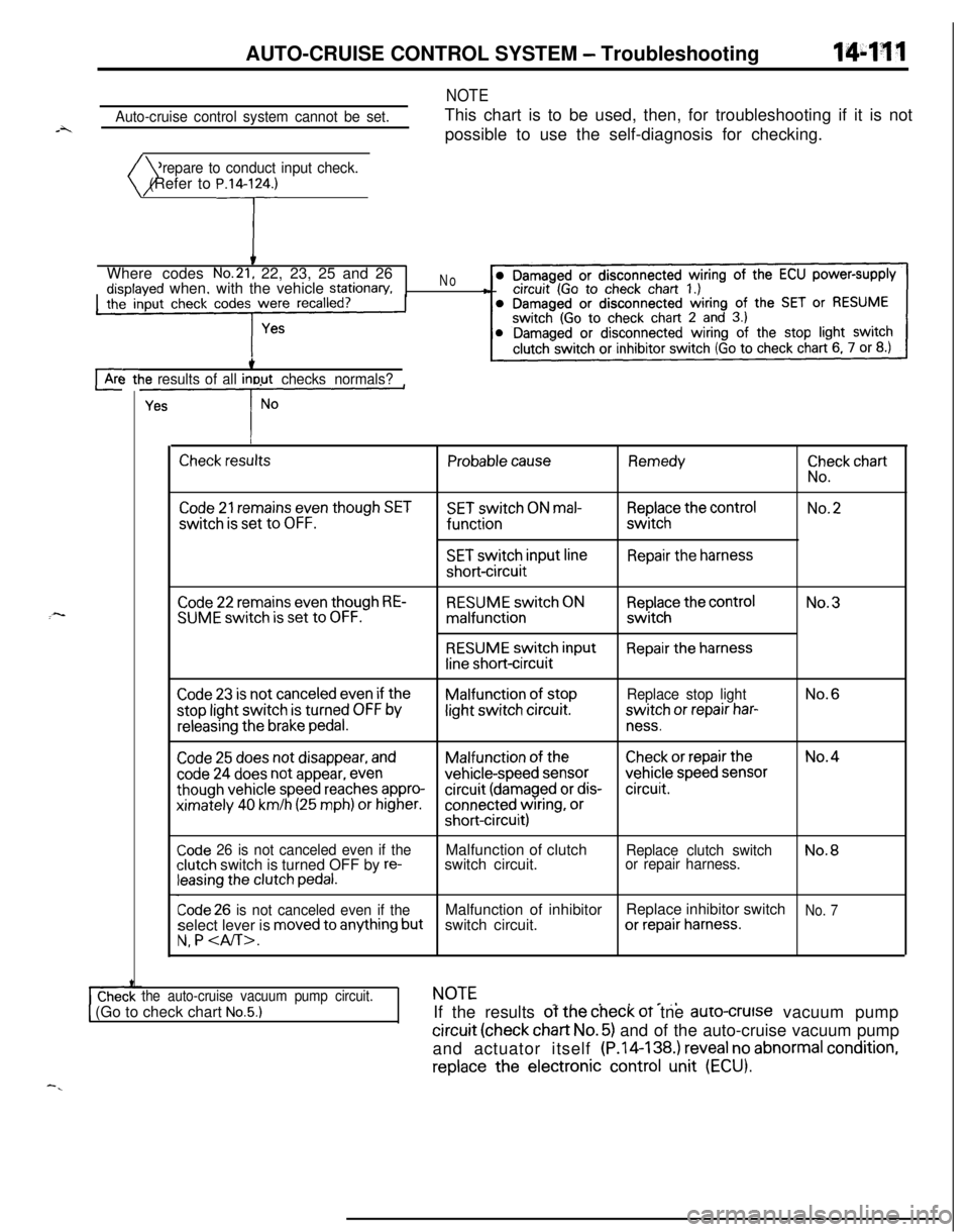
AUTO-CRUISE CONTROL SYSTEM - Troubleshooting144w
Auto-cruise control system cannot be set.
NOTEThis chart is to be used, then, for troubleshooting if it is not
possible to use the self-diagnosis for checking.
Prepare to conduct input check.
)( (Refer to P.14lrWhere codes
No.21, 22, 23, 25 and 26disolaved when, with the vehicle stationary,the’ input check codes were recalled?
‘#
No-8
cArc-3 ttie results of all inout checks normals?
L--y--
I
Check resultsProbable causeRemedy
ii”,:” chart
Code 21 remains even though SETSET switch ON mal-Replace the controlNo.2switch
is set to OFF.functionswitch
SET switch input lineRepair the harnessshort-circuit
:-Code 22 remains even though RE-SUME switch is set to OFF.RESUME switch ONmalfunction
RESUME switch input
line short-circuit
Replace the controlswitch
Repair the harnessNo.3
Code 23 is not canceled even if theMalfunction of stopReplace stop lightNo.6stop light switch
is turned OFF bylight switch circuit.switch or repair har-
releasing the brake pedal.ness.
Code 25 does not disappear, andMalfunction of theCheck or repair theNo.4
code 24 does not appear, evenvehicle-speed sensorvehicle speed sensor
though vehicle speed reaches appro-circuit (damaged or dis-circuit.ximately
40 km/h (25 mph) or higher.connected wiring, orshort-circuit)
Code 26 is not canceled even if theclutch switch is turned OFF by re-leasing the clutch pedal.Malfunction of clutch
switch circuit.
Replace clutch switchNo.8or repair harness.
Code 26 is not canceled even if theMalfunction of inhibitorReplace inhibitor switchNo. 7select lever is moved to anything butswitch circuit.or repair harness.
N, P
the auto-cruise vacuum pump circuit.NOTE_. . . e_,1 (Go to check chart No.5.)IIf the results of the check oT tne auro-crutse vacuum pump
circuit (check chart No. 5) and of the auto-cruise vacuum pump
and actuator itself (P.14-138.) reveal no abnormal
condition,replace
the electronic control unit (ECU).
-.
Page 661 of 1216
STEERING - Service -Adjustment Procedures < Power Steering >IgJf~
4.Disconnect the high-tension cable, and then while operating
the starting motor intermittently, turn the steering wheel all;
the way to the left and right several times to drain all of the
fluid.
Caution, 35
Be careful not to position thq high-tension able ye&r the
carburetor or the delivery pipe.5. Connect the return hoses securely, and then
secur& it ,with
the clip.6. Fill the oil reservoir with the specified fluid up
td the Ibwerposition of the filter, and then bleed the air.
.’
Specified fluid:MOPAR ATF PLUS (Automatic Transmis-sion Fluid Type 7176)/Automatic trans-
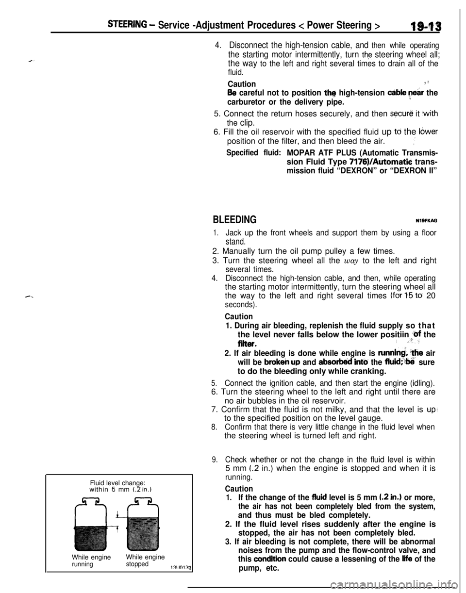
mission fluid “DEXRON” or “DEXRON II”Fluid level change:
within
5 mm (2 in.)While engineWhile engine
runningstoppedl?lrnl?J3
BLEEDINGNlSFKAG
1.Jack up the front wheels and support them by using a floor
stand.2. Manually turn the oil pump pulley a few times.
3. Turn the steering wheel all the way to the left and right
several times.
4.Disconnect the high-tension cable, and then, while operatingthe starting motor intermittently, turn the steering wheel all
the way to the left and right several times
(for 1-5 to 20
seconds).
Caution
1. During air bleeding, replenish the fluid supply so thatthe level never falls below the lower positiin
@f the
eiter.I .“:
2. If air bleeding is done while engine is runnind, ‘the air
will be
brokeir up and absorbed intti the fluid;‘?ti’ sureto do the bleeding only while cranking.
5.Connect the ignition cable, and then start the engine (idling).6. Turn the steering wheel to the left and right until there are
no air bubbles in the oil reservoir.
7. Confirm that the fluid is not milky, and that the level is
upito the specified position on the level gauge.
8.Confirm that there is very little change in the fluid level whenthe steering wheel is turned left and right.
9.Check whether or not the change in the fluid level is within5 mm
(.2 in.) when the engine is stopped and when it is
running.
Caution
1.If the change of the fluid level is 5 mm I.2 in.) or more,
the air has not been completely bled from the system,
and thus must be bled completely.2. If the fluid level rises suddenly after the engine is
stopped, the air has not been completely bled.
3. If air bleeding is not complete, there will be abnormal
noises from the pump and the flow-control valve, and
this
condition could cause a lessening of the life of the
pump, etc.
Page 662 of 1216
19-14STEERING - Service Adjustment Procedures < Power Steering >Shut-off valv
Pressure gauge
(FW close)
(C-3309-E)I
Temperature
gauge
\e’\
Pressure hoses
Re(Mti990994)
\Oil pump
713AO145Shut-off valve
Pressure gauge(FullY ?penl
Pressure hoses
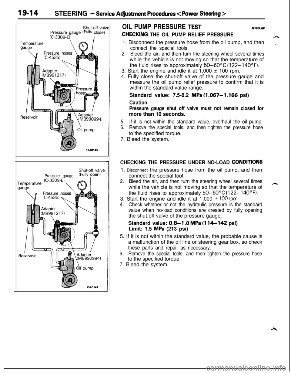
OIL PUMP PRESSURE TESTNl9FlAF
CHECKING THE OIL PUMP RELIEF PRESSURE1. Disconnect the pressure hose from the oil pump, and then
connect the special tools.
2.Bleed the air, and then turn the steering wheel several timeswhile the vehicle is not moving so that the temperature of
the fluid rises to approximately
50-60°C (122-14OOF).3. Start the engine and idle it at 1,000
f 100 rpm.
4. Fully close the shut-off valve of the pressure gauge and
measure the oil pump relief pressure to confirm that it is
within the standard value range.
Standard value: 7.5-8.2
MPa (1,067-1,166 psi)
Caution
Pressure gauge shut off valve must not remain closed formore than 10 seconds.
5.If it is not within the standard value, overhaul the oil pump.
6.Remove the special tools, and then tighten the pressure hoseto the specified torque.
7. Bleed the system.
CHECKING THE PRESSURE UNDER NO-LOAD CONDITIONS1. Disconnect the pressure hose from the oil pump, and then
connect the special tool.
2.Bleed the air, and then turn the steering wheel several timeswhile the vehicle is not moving so that the temperature of
the fluid rises to approximately
50-60°C (122-14OOF).3. Start the engine and idle it at 1,000
-t 100 rpm.
4.
Check whether or not the hydraulic pressure is the standard
value when no-load conditions are created by fully openingthe shut-off valve of the pressure gauge.
Standard value:
0.8-I .O MPa (114-142 psi)
Limit: 1.5
MPa (213 psi)
5. If it is not within the standard value, the probable cause is
a malfunction of the oil line or steering gear box, so check
these parts and repair as necessary.
6.Remove the special tools, and then tighten the pressure hoseto the specified torque.
7. Bleed the system.
Page 869 of 1216
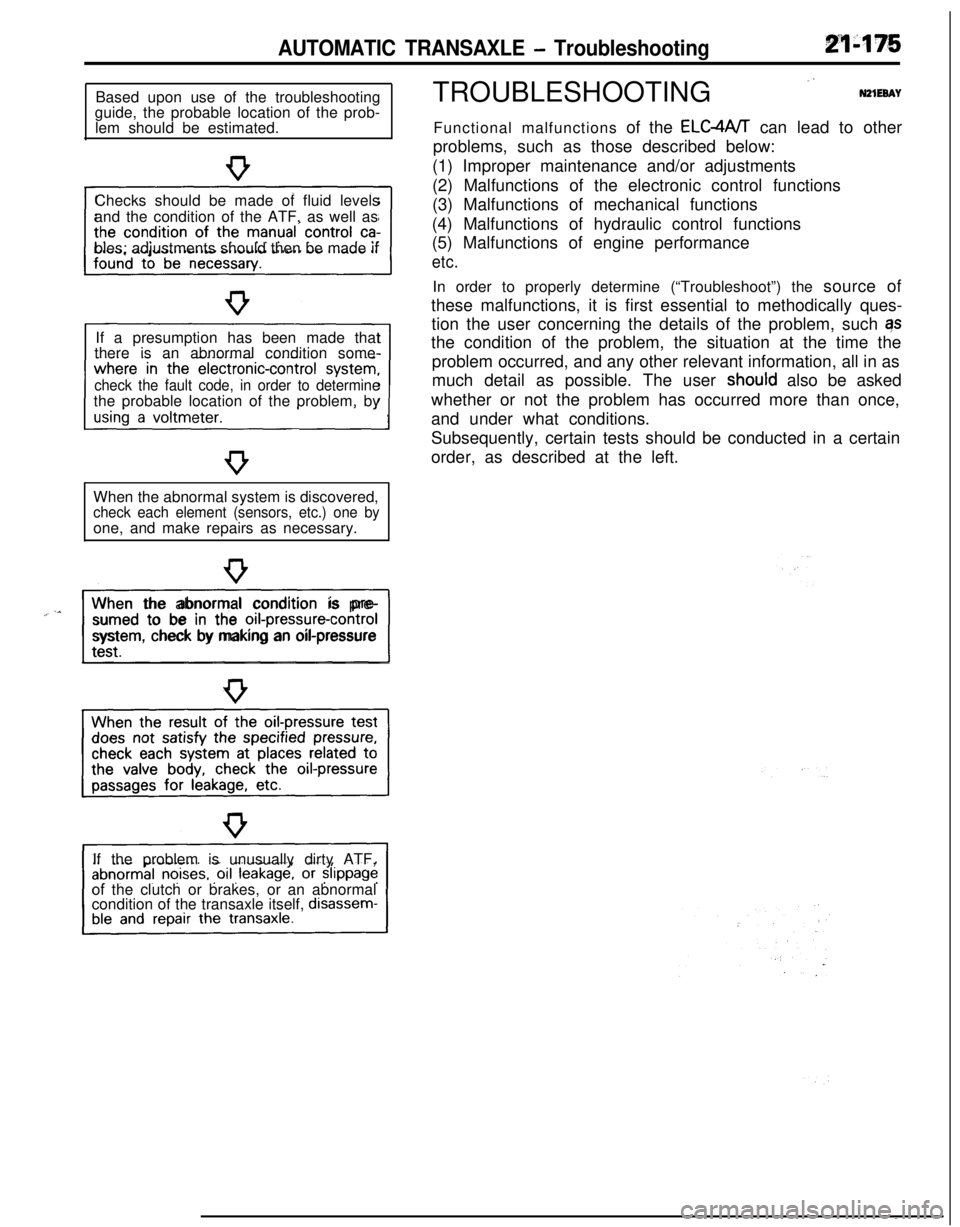
AUTOMATIC TRANSAXLE - TroubleshootingBased upon use of the troubleshooting
guide, the probable location of the prob-
lem should be estimated.
Checks should be made of fluid levels
and the condition of the ATF, as well as
bles; adjustments should then be made if
If a presumption has been made that
there is an abnormal condition some-
check the fault code, in order to determinethe probable location of the problem, by
When the abnormal system is discovered,
check each element (sensors, etc.) one byone, and make repairs as necessary.
“~^II_When the abnormal condition is pre-
sumed to be in the
orI-pressure-controlsystem, check by making an oil-pressure
If the problem is unusually dirty ATF,
of the clutch or brakes, or an abnormal
condition of the transaxle itself,
disassem-TROUBLESHOOTING
”N21EeAYFunctional malfunctions of the ELC4A/T can lead to other
problems, such as those described below:
(1) Improper maintenance and/or adjustments
(2) Malfunctions of the electronic control functions
(3) Malfunctions of mechanical functions
(4) Malfunctions of hydraulic control functions
(5) Malfunctions of engine performance
etc.In order to properly determine (“Troubleshoot”) the source of
these malfunctions, it is first essential to methodically ques-
tion the user concerning the details of the problem, such qs
the condition of the problem, the situation at the time the
problem occurred, and any other relevant information, all in as
much detail as possible. The user
shoutd also be asked
whether or not the problem has occurred more than once,
and under what conditions.
Subsequently, certain tests should be conducted in a certain
order, as described at the left.
Page 872 of 1216
21-178AUTOMATIC TRANSAXLE - Troubleshooting
09P0010Fluid level must be
within this range.09PoOll
0”
Two302
DIAGNOSIS AND TEST
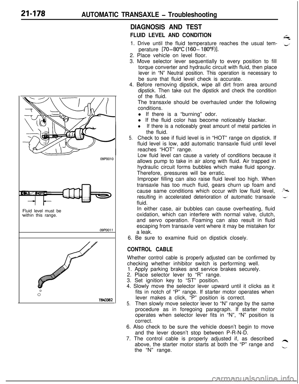
FLUID LEVEL AND CONDITION1. Drive until the fluid temperature reaches the usual tem-
perature
[70-80°C (160- 18O”F)I.2. Place vehicle on level floor.
3. Move selector lever sequentially to every position to fill
torque converter and hydraulic circuit with fluid, then place
lever in “N” Neutral position. This operation is necessary tobe sure that fluid level check is accurate.
4. Before removing dipstick, wipe all dirt from area around
dipstick. Then take out the dipstick and check the conditionof the fluid.
The transaxle should be overhauled under the following
conditions.l If there is a “burning” odor.
l If the fluid color has become noticeably blacker.
lIf there is a noticeably great amount of metal particles inthe fluid.
5.Check to see if fluid level is in “HOT” range on dipstick. If
fluid level is low, add automatic transaxle fluid until level
reaches “HOT” range.
Low fluid level can cause a variety of conditions because itallows pump to take in air along with fluid. Air trapped in
hydraulic circuit forms bubbles which make fluid spongy.
Therefore, pressures will be erratic.
Improper filling can also raise fluid level too high. When
transaxle has too much fluid, gears churn up foam and
cause same conditions which occur with low fluid level,
resulting in accelerated deterioration of automatic transaxle
fluid.In either case, air bubbles can cause overheating, fluid
oxidation, which can interfere with normal valve, clutch,
and servo operation. Foaming can also result in fluid
escaping from transaxle vent where it may be mistaken for
a leak.
6. Be sure to examine fluid on dipstick closely.
CONTROL CABLE
Whether control cable is properly adjusted can be confirmed bychecking whether inhibitor switch is performing well.
1. Apply parking brakes and service brakes securely.
2. Place selector lever to “R” range.
3. Set ignition key to “ST” position.
4. Slowly move the selector lever upward until it clicks as it
fits in notch of “P” range. If starter motor operates when
lever makes a click, “P” position is correct.
5.Then slowly move selector lever to “N” range by the same
procedure as in foregoing paragraph. If starter motor
operates when selector lever fits in “N”, “N” position is
correct.6. Also check to be sure the vehicle doesn’t begin to move
and the lever doesn’t stop between P-R-N-D.
7. The control cable is properly adjusted if, as described
above, the starter motor starts at both the “P” range and
the “N” range.
Page 877 of 1216
AUTOMATIC TRANSAXLE - Troubleshooting214%3
TRANSAXLE CONTROL UNIT
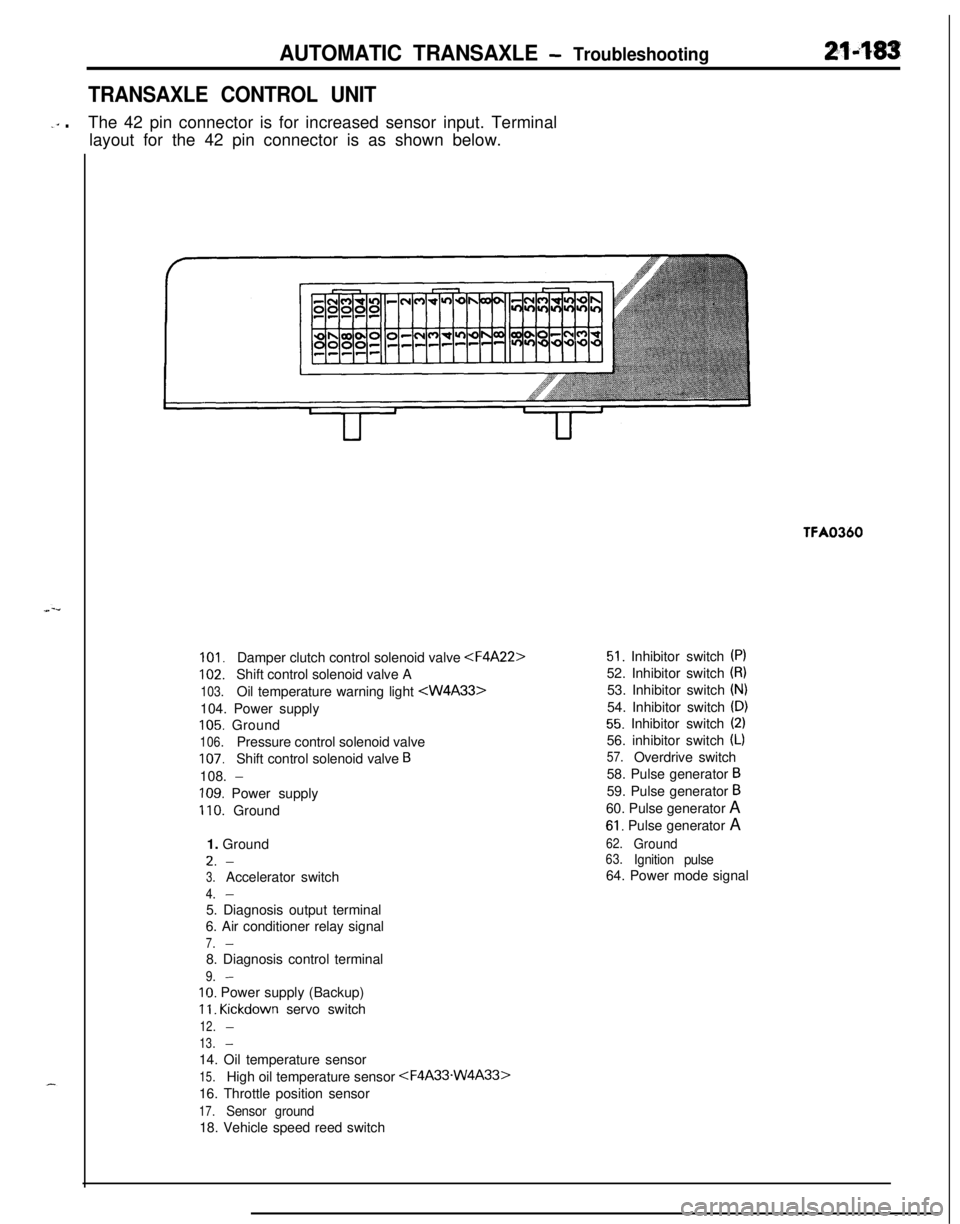
-‘” .The 42 pin connector is for increased sensor input. Terminal
layout for the 42 pin connector is as shown below.TFA0360
101.Damper clutch control solenoid valve
102.Shift control solenoid valve A
103.Oil temperature warning light
105. Ground
106.Pressure control solenoid valve
107.Shift control solenoid valve B108.
-
109. Power supply
110. Ground
1. GroundL.
-
3.Accelerator switch
4.-5. Diagnosis output terminal
6. Air conditioner relay signal
7.-8. Diagnosis control terminal
9.-
IO. Power supply (Backup)
11. Kickdown servo switch
12.-
13.-14. Oil temperature sensor
15.High oil temperature sensor
16. Throttle position sensor
17.Sensor ground18. Vehicle speed reed switch
51. Inhibitor switch (PI52. Inhibitor switch
(8)53. Inhibitor switch
(N)54. Inhibitor switch
(D)
55. Inhibitor switch (2)56. inhibitor switch
(L)
57.Overdrive switch
58. Pulse generator
B59. Pulse generator
B60. Pulse generator A
61. Pulse generator A
62.Ground63.Ignition pulse64. Power mode signal
Page 889 of 1216
AUTOMATIC TRANSAXLE - Troubleshooting21'495
OIL PRESSURE TESTS
1.
2.
3.
4.
5.Completely warm up the transaxle.
.”Raise the vehicle by using a jack so that the drive wheels
can be rotated.
Connect an engine tachometer and place it in a position
where it’s easy to see.
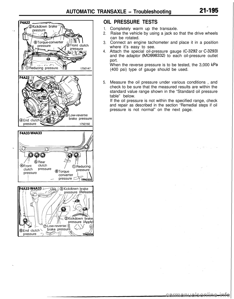
Attach the special oil-pressure gauge
(C-3292 or C-3293)and the adaptor
(MD998332) to each oil-pressure outlet
port.When the reverse pressure is to be tested, the 3,000
kPa(400 psi) type of gauge should be used.
Measure the oil pressure under various conditions , and
check to be sure that the measured results are within the
standard value range shown in the “Standard oil pressure
table” below.
If the oil pressure is not within the specified range, check
and repair as described in the section “Remedial steps if oilpressure is not normal” on the next page.
m // @ Kickdown brake
Page 899 of 1216
AUTOMATIC TRANSAXLE - Troubleshooting21-205
AIR CONDITIONER
CONTROL UNITIGNI
CRCFILTER
B-11
ON+OFF:2700kP.%(384Psl)OFF+ON:
$;X;kERATOR
SWITCH
WITH
WITHOUT,$J;$JR~;UISE 1AUTO-CRUISE. CONTROL
SELFJ-DIAGNOSIS
CONNECTOR
TIO1
/-1. 8LENGINE
3J
I
IL.&.j IUK1
mB
x 1
mm
CLCL
--
‘----_06
Pz
1_----
t
29I
POWE
TRANSTOR
c-30
FRONT SIDE
p&a-q
E%ERSE
p!!iQqI-----
101
NON-TURBC
/ 0
2_----II
A
-----02
9
I.----,
IL-B
GtD G:DGB“tD----1
B-24 4-SPEED AUTOMATICTRANSAXLE SOLENOID VALVE
Remark*%Mark indicates the optional wlrlnsharness for auto-cruise control system.KX35-AC-U0705A-NCfg
Page 903 of 1216
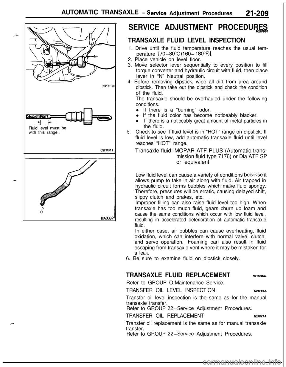
AUTOMATIC TRANSAXLE - service Adjustment Procedures21-209
09Pooi awith this range.
09POOll
TWO382
SERVICE ADJUSTMENT PROCEDURESN21FB6E
TRANSAXLE FLUID LEVEL INSPECTION1. Drive until the fluid temperature reaches the usual tem-
perature
[70-80°C (160- 18O”F)I.2. Place vehicle on level floor.
3. Move selector lever sequentially to every position to fill
torque converter and hydraulic circuit with fluid, then place
lever in “N” Neutral position.
4. Before removing dipstick, wipe all dirt from area around
dipstick. Then take out the dipstick and check the conditionof the fluid.
The transaxle should be overhauled under the following
conditions.l If there is a “burning” odor.
l If the fluid color has become noticeably blacker.
lIf there is a noticeably great amount of metal particles inthe fluid.
5.Check to see if fluid level is in “HOT” range on dipstick. If
fluid level is low, add automatic transaxle fluid until level
reaches “HOT” range.
Transaxle fluid: MOPAR ATF PLUS (Automatic trans-
mission fluid type 7176) or Dia ATF SPor equivalent
Low fluid level can cause a variety of conditions
becaljse it
allows pump to take in air along with fluid. Air trapped in
hydraulic circuit forms bubbles which make fluid spongy.
Therefore, pressures will be erratic, causing delayed shift,
slippy clutch and brakes, etc.
Improper filling can also raise fluid level too high. When
transaxle has too much fluid, gears churn up foam and
cause the same conditions which occur with low fluid level,
resulting in accelerated deterioration of automatic transaxle
fluid.In either case, air bubbles can cause overheating, fluid
oxidation, which can interfere with normal valve, clutch,
and servo operation.Foaming can also result in fluid
escaping from transaxle vent where it may be mistaken for
a leak.6. Be sure to examine fluid on dipstick closely.
TRANSAXLE FLUID REPLACEMENTN21FCBAaRefer to GROUP O-Maintenance Service.
TRANSFER OIL LEVEL INSPECTIONNZlFXAATransfer oil level inspection is the same as for the manual
transaxle transfer.
Refer to GROUP
22-Service Adjustment Procedures.
TRANSFER OIL REPLACEMENTNZlFYAFaTransfer oil replacement is the same as for manual transaxle
transfer.Refer to GROUP
22-Service Adjustment Procedures.
Page 1145 of 1216

24-l
HEATERS ANDAIR CONDITIONING
CONTENTSN24M--AIR CONDITIONER SWITCH
..........................30BLOWER ASSEMBLY
.....................................33
COMPRESSOR.................................................37CONDENSER AND CONDENSER FAN
MOTOR............................................................45ENGINE COOLANT TEMPERATURE
-‘-.,SWITCH............................................................51
EVAPORATOR.................................................
34
HEATERCONTROLASSEMBLY....................
26HEATER UNIT
.................................................31
REFRIGERANTLINE........................................47
RESISTOR........................................................29SAFETY PRECAUTIONS
.................................10SERVICE ADJUSTMENT PROCEDURES..
.....11Compressor Drive
Belt Adjustment
.............
23
CompressorNoise........................................24
Handling
TubingandFittings.......................22Idle-up
OperationCheck..............................25Manifold
GaugeSetInstallation..................11Performance Test
.........................................16Power Relay Check
......................................24Refrigerant Leak Repair Procedure
.............17
TestingSystemforLeaks...........................15Test Procedures
...........................................11
SPECIFICATIONS.............................................2
General Specifications..................................2
Lubricants......................................................3Sealant and Adhesives
.................................3Service Specifications
...................................2
TorqueSpecifications...................................2
TROUBLESHOOTING. . . ..a................................3
VENTILATORS(AIR INLET AND AIR OUTLET)
..,....s............. 50
VENTILATORS(INSTRUMENT PANEL)
..,...................*...........49