ECU MITSUBISHI ECLIPSE 1991 Service Manual
[x] Cancel search | Manufacturer: MITSUBISHI, Model Year: 1991, Model line: ECLIPSE, Model: MITSUBISHI ECLIPSE 1991Pages: 1216, PDF Size: 67.42 MB
Page 1119 of 1216
BODY - Aero Parts23-75
\18A0245
16A0765
18A041618A041C
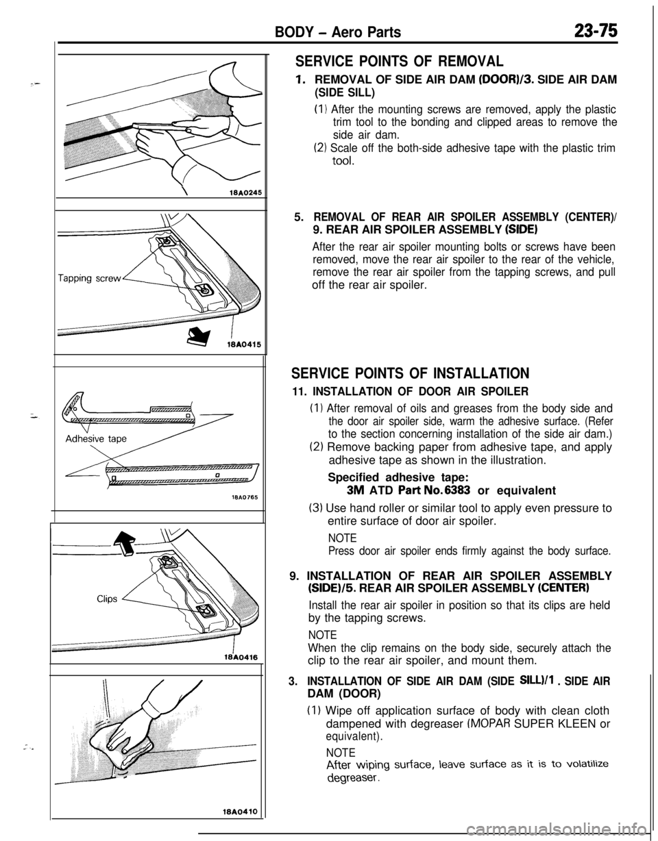
SERVICE POINTS OF REMOVAL
1.REMOVAL OF SIDE AIR DAM (DOOR)/3. SIDE AIR DAM
(SIDE SILL)(I
1 After the mounting screws are removed, apply the plastic
trim tool to the bonding and clipped areas to remove the
side air dam.
(21 Scale off the both-side adhesive tape with the plastic trim
tool.5.
REMOVAL OF REAR AIR SPOILER ASSEMBLY (CENTER)/9. REAR AIR SPOILER ASSEMBLY
(SIDE)
After the rear air spoiler mounting bolts or screws have been
removed, move the rear air spoiler to the rear of the vehicle,
remove the rear air spoiler from the tapping screws, and pulloff the rear air spoiler.
SERVICE POINTS OF INSTALLATION
11. INSTALLATION OF DOOR AIR SPOILER(I
1 After removal of oils and greases from the body side and
the door air spoiler side, warm the adhesive surface. (Refer
to the section concerning installation of the side air dam.)
(2) Remove backing paper from adhesive tape, and apply
adhesive tape as shown in the illustration.
Specified adhesive tape:
3M ATD Part No.6383 or equivalent
(3) Use hand roller or similar tool to apply even pressure to
entire surface of door air spoiler.
NOTE
Press door air spoiler ends firmly against the body surface.9. INSTALLATION OF REAR AIR SPOILER ASSEMBLY
(SIDE)/5. REAR AIR SPOILER ASSEMBLY (CENTER)
Install the rear air spoiler in position so that its clips are heldby the tapping screws.
NOTE
When the clip remains on the body side, securely attach theclip to the rear air spoiler, and mount them.
3.INSTALLATION OF SIDE AIR DAM (SIDE SILL)/1 . SIDE AIRDAM (DOOR)
(I 1 Wipe off application surface of body with clean cloth
dampened with degreaser
IMOPAR SUPER KLEEN or
equivalent).
NOTE
After wiping surface, leave surface as it is to volatilize
degreaser .
Page 1131 of 1216
BODY - Trims23-871@Poo70
10P0081
Trim
Gro19P0000
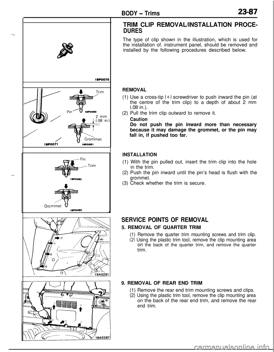
TRIM CLIP REMOVAL/INSTALLATION PROCE-
DURESThe type of clip shown in the illustration, which is used for
the installation of. instrument panel, should be removed and
installed by the following procedures described below.
REMOVAL
(1) Use a cross-tip (+) screwdriver to push inward the pin (at
the centre of the trim clip) to a depth of about 2 mm
(.08 in.).
(2) Pull the trim clip outward to remove it.
CautionDo not push the pin inward more than necessary
because it may damage the grommet, or the pin may
fall in, if pushed too far.
INSTALLATION(1) With the pin pulled out, insert the trim clip into the hole
in the trim.
(2) Push the pin inward until the pin’s head is flush with the
grommet.(3) Check whether the trim is secure.
SERVICE POINTS OF REMOVAL5. REMOVAL OF QUARTER TRIM
(1) Remove the quarter trim mounting screws and trim clip.
(2) Using the plastic trim tool, remove the clip mounting areaon the back of the quarter trim, and remove the quarter
trim.9. REMOVAL OF REAR END TRIM
(1) Remove the rear end trim mounting screws and clips.
(2) Using the plastic trim tool, remove the clip mounting areaon the back of the rear end trim, and remove the rear
end trim.
Page 1135 of 1216
-
BODY - Front Seat23-91
Bolts
19AO308
FrontFront seat forward
installation bracket
A-A cross-section
Forward tab
.)\&Front seat’s rearz-2 bracketarea mounting
1Lanchor\
coverForward tabB-B cross-section19A0124
Slid; railSlide kail’sreararea mounting
bracketWA0302
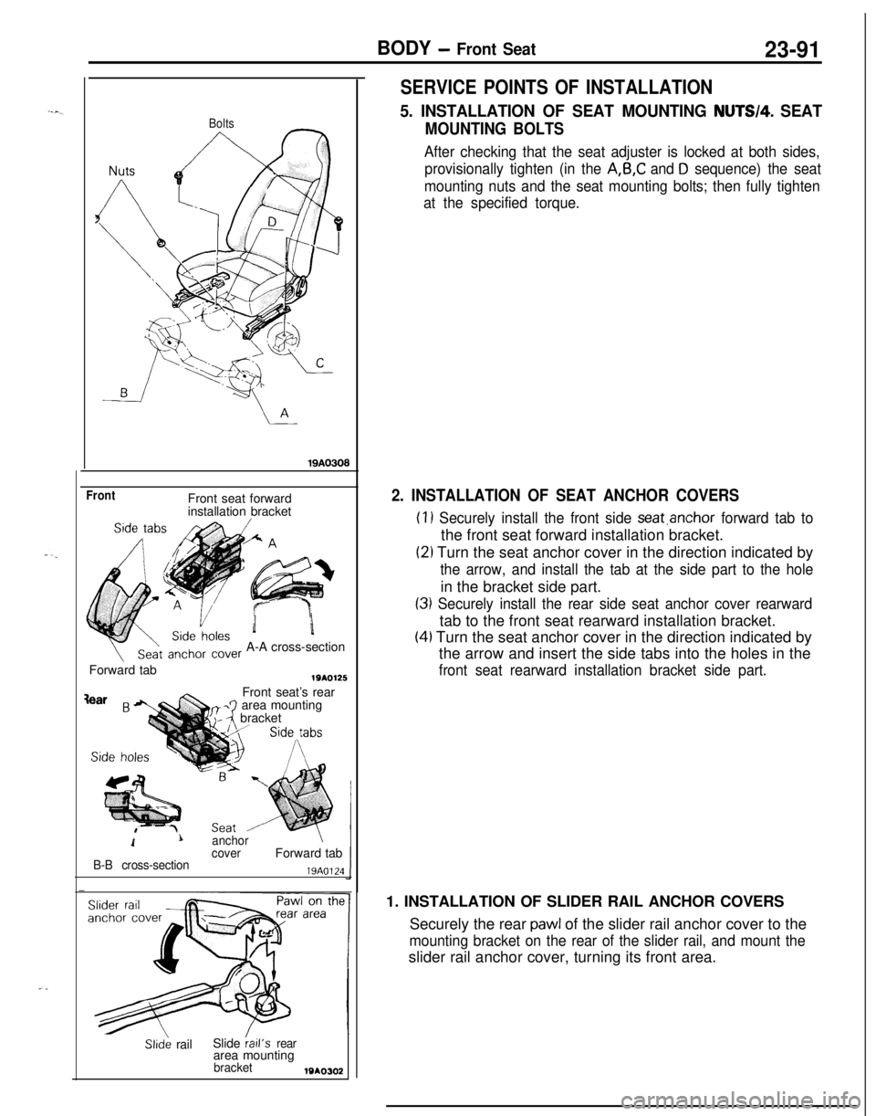
SERVICE POINTS OF INSTALLATION
5. INSTALLATION OF SEAT MOUNTING NUTW4. SEAT
MOUNTING BOLTS
After checking that the seat adjuster is locked at both sides,
provisionally tighten (in the
A,B,C and D sequence) the seat
mounting nuts and the seat mounting bolts; then fully tighten
at the specified torque.
2. INSTALLATION OF SEAT ANCHOR COVERS
(1) Securely install the front side seat.anchor forward tab tothe front seat forward installation bracket.
(21 Turn the seat anchor cover in the direction indicated by
the arrow, and install the tab at the side part to the holein the bracket side part.
(3) Securely install the rear side seat anchor cover rearwardtab to the front seat rearward installation bracket.
(4) Turn the seat anchor cover in the direction indicated by
the arrow and insert the side tabs into the holes in the
front seat rearward installation bracket side part.1. INSTALLATION OF SLIDER RAIL ANCHOR COVERS
Securely the rear
pawl of the slider rail anchor cover to the
mounting bracket on the rear of the slider rail, and mount theslider rail anchor cover, turning its front area.
Page 1137 of 1216
BODY - Rear Seat23-93
REAR SEATN23UFAN
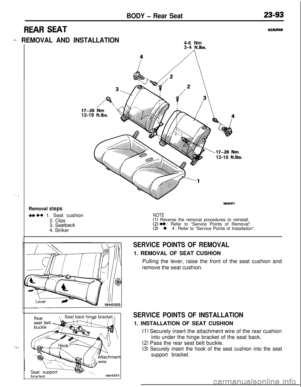
.~x REMOVAL AND INSTALLATION4-6 Nm
3-4
ft.lbs.
A12-19
ft.lbs.12-19
ft.lbs.
Removal steps
w w 1. Seat cushion
2. Clips3. Seatback4. Striker
19AO411
NOTE(1) Reverse the removal procedures to reinstall.(2) +* : Refer to “Service Points of Removal”.(3) l 4 : Refer to “Service Points of Installation”.
ISeat back hinge bracket I
Seatbracket
1910323
SERVICE POINTS OF REMOVAL1. REMOVAL OF SEAT CUSHION
Pulling the lever, raise the front of the seat cushion and
remove the seat cushion.
SERVICE POINTS OF INSTALLATION1. INSTALLATION OF SEAT CUSHION
(1) Securely insert the attachment wire of the rear cushion
into under the hinge bracket of the seat back.
(2) Pass the rear seat belt buckle.
(3) Securely insert the hook of the seat cushion into the seat
support bracket.
Page 1143 of 1216
BODY - Seat Belt23-99
19AO239
I ITest bulb 2tI
I I
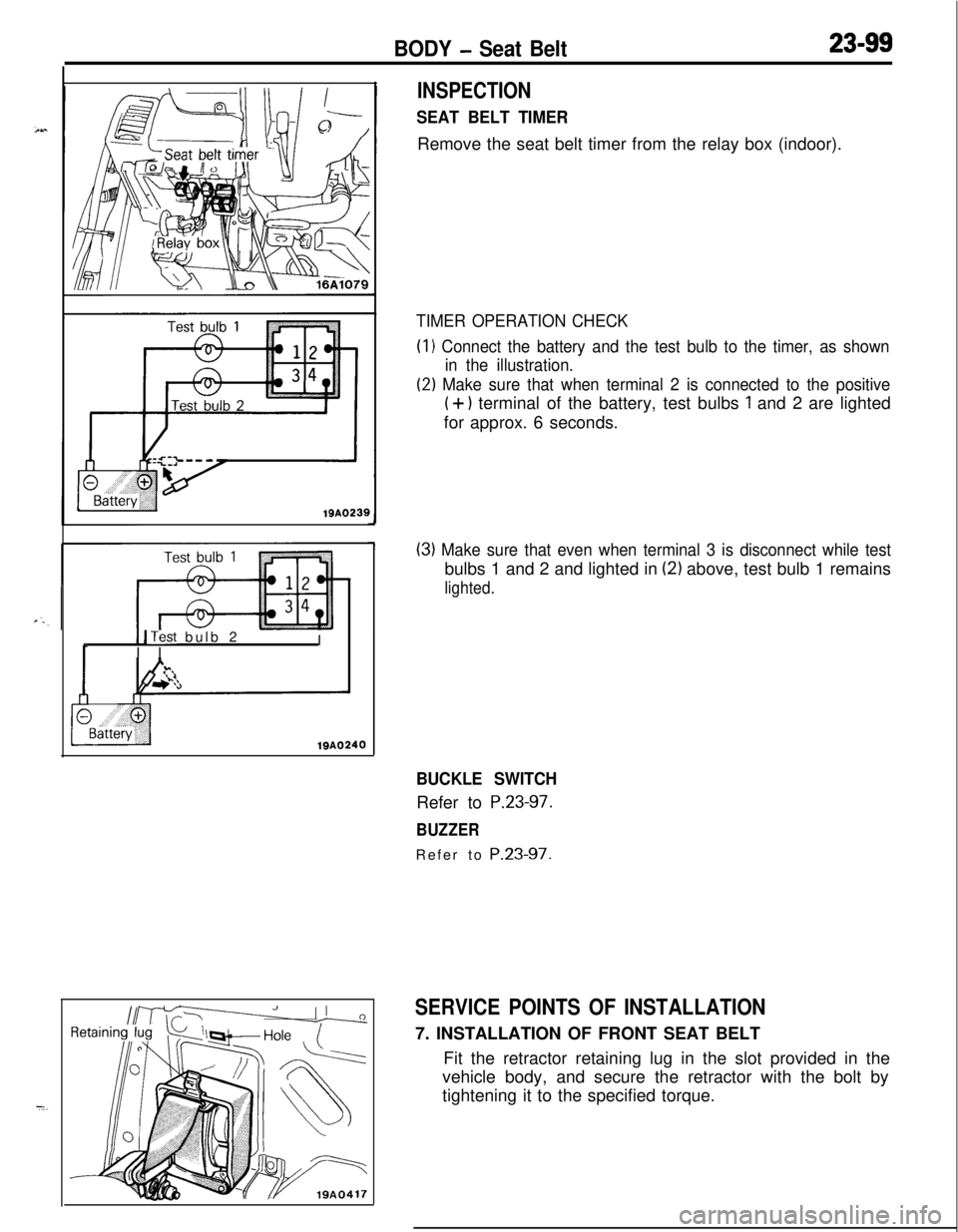
INSPECTION
SEAT BELT TIMERRemove the seat belt timer from the relay box (indoor).
TIMER OPERATION CHECK(I
1 Connect the battery and the test bulb to the timer, as shown
in the illustration.
(2) Make sure that when terminal 2 is connected to the positive
(+) terminal of the battery, test bulbs 1 and 2 are lighted
for approx. 6 seconds.
(3) Make sure that even when terminal 3 is disconnect while testbulbs 1 and 2 and lighted in
(2) above, test bulb 1 remains
lighted.
BUCKLE SWITCHRefer to
P.23-97.
BUZZERRefer to
P.23-97.
SERVICE POINTS OF INSTALLATION7. INSTALLATION OF FRONT SEAT BELT
Fit the retractor retaining lug in the slot provided in the
vehicle body, and secure the retractor with the bolt by
tightening it to the specified torque.
Page 1172 of 1216
24-28HEATERS AND AIR CONDITIONING - Heater Control Assembly
II
IT20AO409
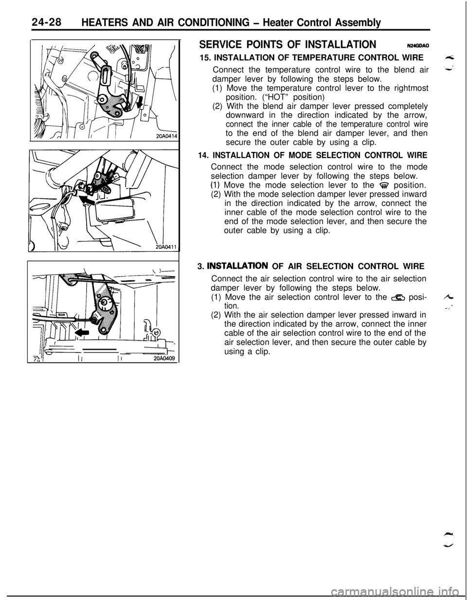
SERVICE POINTS OF INSTALLATIONN24GOAO
15. INSTALLATION OF TEMPERATURE CONTROL WIRE
Connect the temperature control wire to the blend air
damper lever by following the steps below.
(1) Move the temperature control lever to the rightmost
position. (“HOT” position)
(2) With the blend air damper lever pressed completely
downward in the direction indicated by the arrow,
connect the inner cable of the temperature control wireto the end of the blend air damper lever, and then
secure the outer cable by using a clip.
14. INSTALLATION OF MODE SELECTION CONTROL WIREConnect the mode selection control wire to the mode
selection damper lever by following the steps below.
(1) Move the mode selection lever to the $$ position.
(2) With the mode selection damper lever pressed inward
in the direction indicated by the arrow, connect the
inner cable of the mode selection control wire to the
end of the mode selection lever, and then secure the
outer cable by using a clip.
3. INSTALLATlON OF AIR SELECTION CONTROL WIRE
Connect the air selection control wire to the air selection
damper lever by following the steps below.
(1) Move the air selection control lever to the
& posi-
tion.(2) With the air selection damper lever pressed inward in
the direction indicated by the arrow, connect the inner
cable of the air selection control wire to the end of the
air selection lever, and then secure the outer cable by
using a clip.