check engine MITSUBISHI ECLIPSE 1991 Service Manual
[x] Cancel search | Manufacturer: MITSUBISHI, Model Year: 1991, Model line: ECLIPSE, Model: MITSUBISHI ECLIPSE 1991Pages: 1216, PDF Size: 67.42 MB
Page 882 of 1216
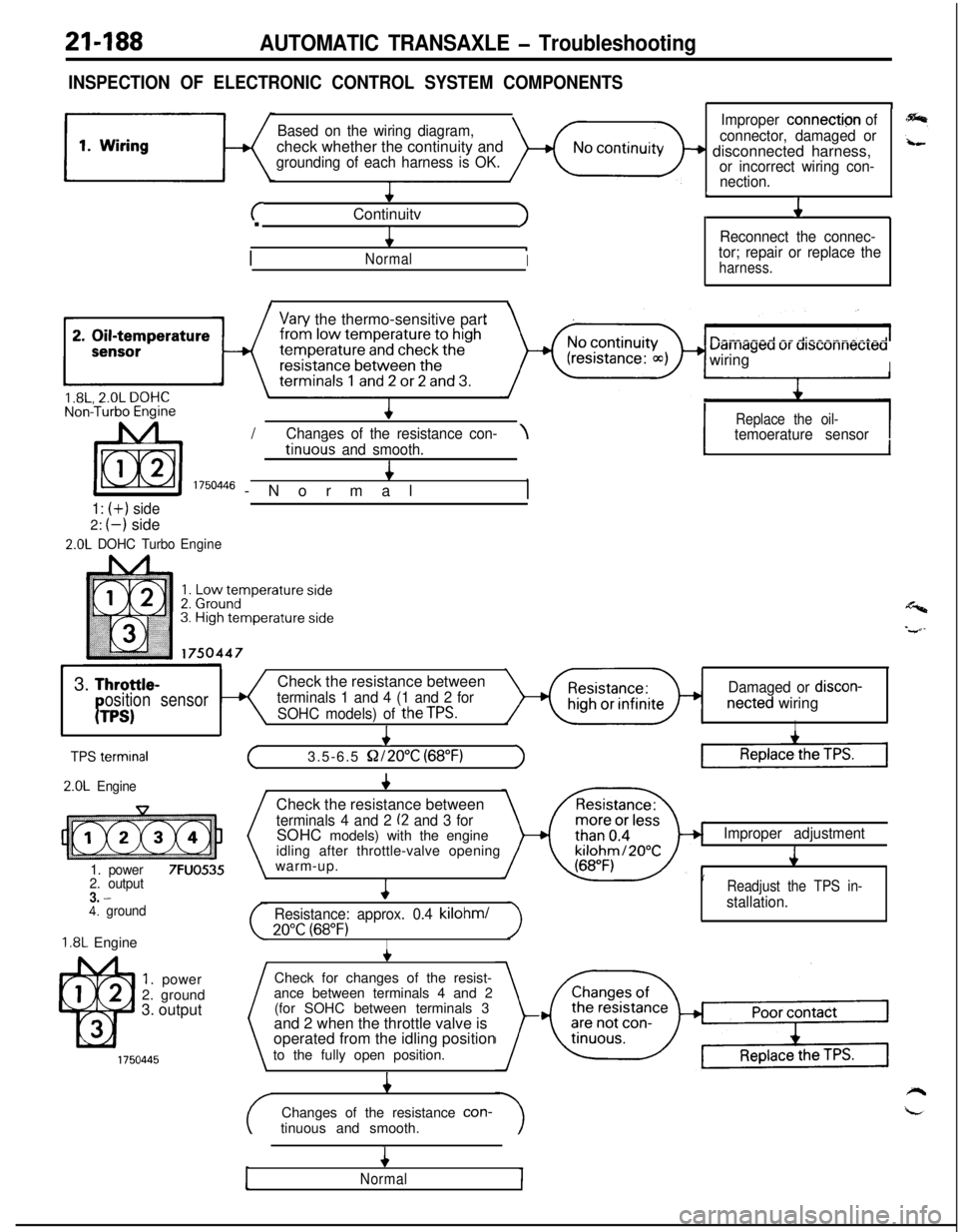
21-188AUTOMATIC TRANSAXLE - Troubleshooting
INSPECTION OF ELECTRONIC CONTROL SYSTEM COMPONENTS
Based on the wiring diagram,check whether the continuity and
grounding of each harness is OK.
+
cContinuitvJ.
4
/
.NormalI
1
Improper connection of
connector, damaged or
+ disconnected harness,or incorrect wiring con-
nection.
L
J1
Reconnect the connec-
tor; repair or replace the
harness.
I\
Vary the thermo-sensitive part
uarriageu ur ursconnecreawiring
I/
IReplace the oil-Chanaes of the resistance con-\temoerature sensortinuo& and smooth.4
I 1750446 -Normal,
1: (+) side2:
(-) side
2.0L DOHC TurboEngine
1I
Y3.
Throttle-Check the resistance betweenosition sensorterminals 1 and 4 (1 and 2 forDamaged or discon-
PTPS)SOHC models) of theTPS.netted wiringI
I
TPS termrnal
2.0L Engine
1. power
7FUO5352. output3. -4. ground
1.8L Engine
1. power
2. ground
3. output
+
(3.5-6.5 S2/2O”C (68°F)1Check the resistance between
terminals 4 and 2 (2 and 3 forSOHC models) with the engine
idling after throttle-valve opening
warm-up.
4
Resistance: approx. 0.4 kilohml
20°C (68°F)I
Improper adjustment
J
’Readjust the TPS in-
stallation.Check for changes of the resist-
ance between terminals 4 and 2
(for SOHC between terminals 3
and 2 when the throttle valve is
operated from the idling position
to the fully open position.
4Changes of the resistance con-
tinuous and smooth.
4
Normal
Page 883 of 1216
AUTOMATIC TRANSAXLE - Troubleshooting21-189
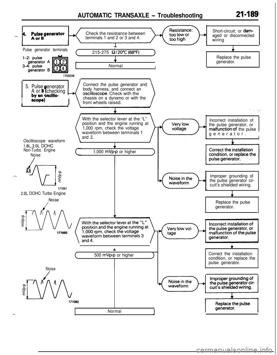
_ 4, ppBgeneratorCheck the resistance betweenterminals 1 and 2 or 3 and 4.Short-circuit; or
dam-aged or disconnectedwiring
:
I
.
4
/
NormalI
1750338II\
Pulse generator terminals.(215-275 Q/2O”C (68°F)1
5. PulseeneratorConnect the pulse generator and
A or B?checkingwbody harness, and connect an
+ mm narillroscilloscooe. Check with the\
I
#, -mm v3nlwdP
scope)I \
chassis on a dynamo or with thefront wheels raised.
With the selector lever at the “L”
position and the engine running at
1,000 rpm, check the voltagewaveform between terminals 1
and 2.
Oscilloscope waveform
1,8L, 2.0L DOHCNon-Turbo Engine
Noise
/AA_--
iw
5E4
1,000 mVp-p or higher>
171091
2.0L DOHC Turbo Engine
,Noise
Replace the pulse
generator.
. . .,’
Incorrect installation of
the pulse generator, or
malfunction,of the pulsegenerator.
II
Improper grounding of
the pulse generator cir-cuit’s shielded wiring.
i
Replace the pulse
generator.+
(500 mVp-p or higherJ
Noise
Normal1
+,I
Correct the installation
condition, or replace the /pulse generator.
Page 886 of 1216
21-192AUTOMATIC TRANSAXLE - Troubleshooting
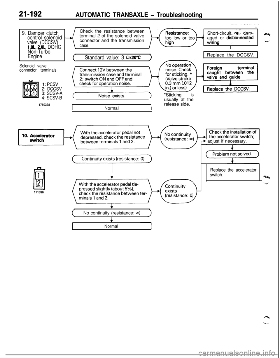
9. Damper clutchcontrol solenoid
valve (DCCSV)
1,8L, 2.0L DOHC
Non-Turbo
Engine
Solenoid valve
connector terminals1:
PCSV2: DCCSV
3: SCSV-A4:
SCSV-B
1750338Check the resistance between
terminal 2 of the solenoid valve
connector and the transmission
case.too low or too
G’Short-circuit
0,s” dam-
aged or d&connectedwiring
.: ’
I
(Standard value: 3 Q/20%)I
INormalI*Sticking *Sticking
is isusually at the usually at the
release side. release side.
1 Replace the DCCSV. 1
171096
b adjust if necessary.
Replace the acceleratorswitch.
(No continuity (resistance: Q)))4
Normal
Page 888 of 1216
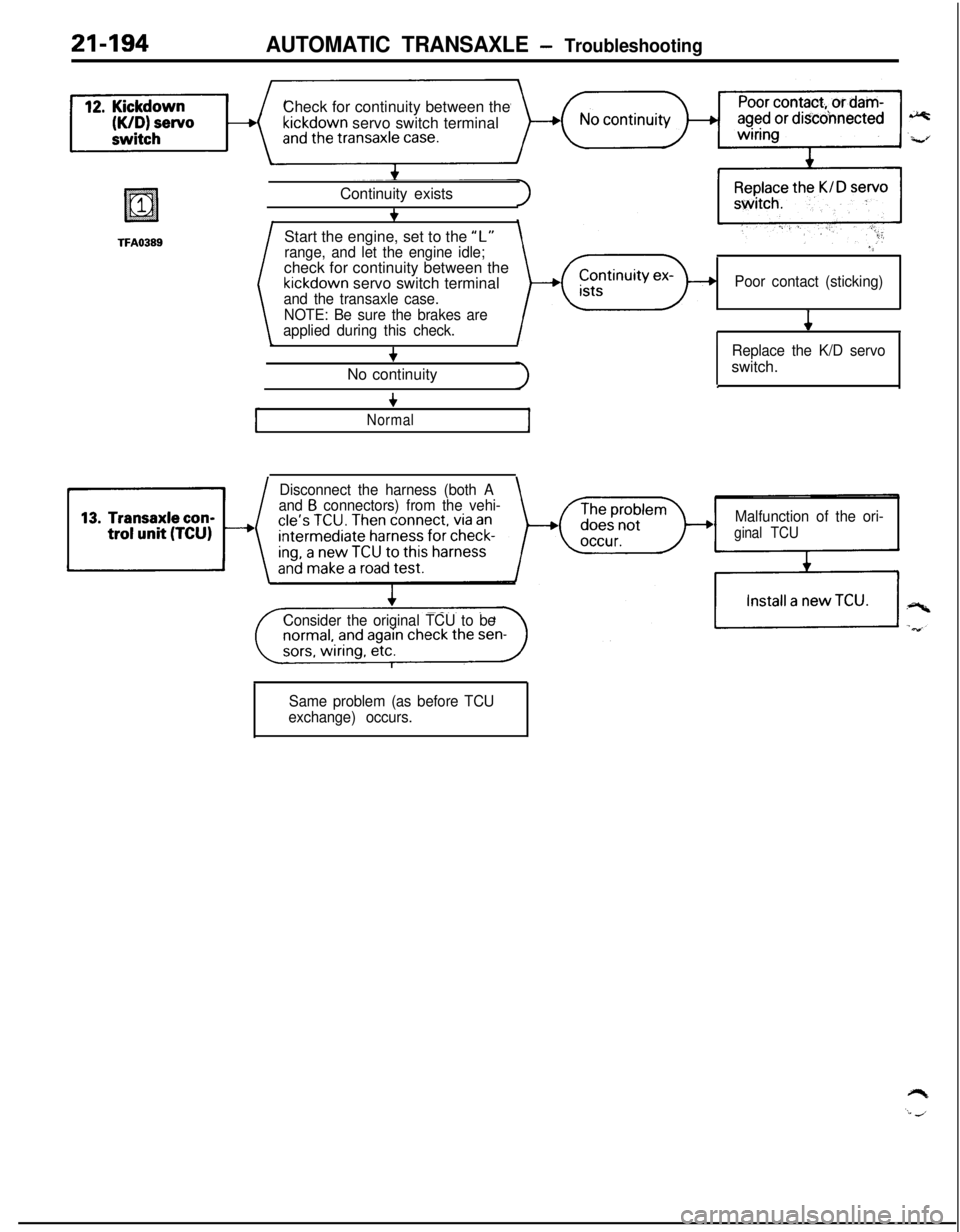
21-194AUTOMATIC TRANSAXLE - TroubleshootingCheck for continuity between the
kickdown servo switch terminal
TFA0389Start the engine, set to the “L”Continuity exists
+
range, and let the engine idle;check for continuity between the
kickdown servo switch terminaland the transaxle case.
NOTE: Be sure the brakes are
applied during this check.
+No continuity
“‘
Poor contact (sticking)
4
Replace the K/D servoswitch.
.
+
Normal
Disconnect the harness (both A
and B connectors) from the vehi-
Malfunction of the ori-
ginal TCU
Consider the original TCU to be
Same problem (as before TCU
exchange) occurs.
Page 889 of 1216
AUTOMATIC TRANSAXLE - Troubleshooting21'495
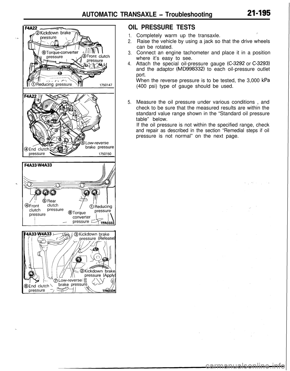
OIL PRESSURE TESTS
1.
2.
3.
4.
5.Completely warm up the transaxle.
.”Raise the vehicle by using a jack so that the drive wheels
can be rotated.
Connect an engine tachometer and place it in a position
where it’s easy to see.
Attach the special oil-pressure gauge
(C-3292 or C-3293)and the adaptor
(MD998332) to each oil-pressure outlet
port.When the reverse pressure is to be tested, the 3,000
kPa(400 psi) type of gauge should be used.
Measure the oil pressure under various conditions , and
check to be sure that the measured results are within the
standard value range shown in the “Standard oil pressure
table” below.
If the oil pressure is not within the specified range, check
and repair as described in the section “Remedial steps if oilpressure is not normal” on the next page.
m // @ Kickdown brake
Page 896 of 1216
21-202AUTOMATIC TRANSAXLE - Troubleshooting
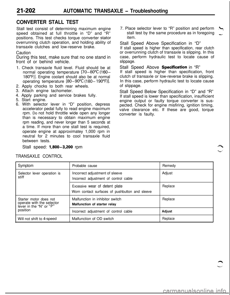
CONVERTER STALL TESTStall test consist of determining maximum engine
speed obtained at full throttle in “D” and “R”
positions. This test checks torque converter stator
overrunning clutch operation, and holding ability of
transaxle clutches and low-reserve brake.
CautionDuring this test, make sure that no one stand in
front of or behind vehicle.
1. Check transaxle fluid level. Fluid should be at
normal operating temperature
[70-80°C (160-
18O”F)]. Engine coolant should also be at normaloperating temperature
[80-90°C (180- 19O”F)l.2. Apply chocks to both rear wheels.
3. Attach engine tachometer.
4. Apply parking and service brakes fully.
5. Start engine.
6. With selector lever in “D” position, depress
accelerator pedal fully to read engine maximum
rpm. Do not hold throttle wide open any longer
than is necessary to obtain maximum engine
rpm reading, and never longer than 5 seconds ata time. If more than one stall test is required,
operate engine at approximatey 1,000 rpm in
neutral for 2 minutes to cool transaxle fluid
between tests.
Stall speed:
1,800-3,200 rpm
TRANSAXLE CONTROL7. Place selector lever to “R” position and perform
?+stall test by the same procedure as in foregoing
-,
item.Stall Speed Above Specification in “D”
If stall speed is higher than specification, rear clutchor overrunning clutch of transaxle is slipping. In this
case, perform hydraulic test to locate cause of
slippage.Stall Speed Above Specifjcation in “R”
If stall speed is higher than specification, front
clutch of transaxle or low-reverse brake is slipping.
In this case, perform hydraulic test to locate cause
of slippage.
Stall Speed Below Specification in “D” and “R”
If stall speed is lower than specification, insufficient
engine output or faulty torque converter is sus-
pected. Check for engine misfiring, ignition timing,
valve clearance etc. If these are good, torque
converter is faulty.
Symptom
Selector lever operation isstiff
Probable causeIncorrect adjustment of sleeve
Incorrect adjustment of control cable
Excessive wear of detent plate
Worn contact surfaces of pushbutton and sleeveRemedyAdjust
Replace
Starter motor does notoperate with the selector
lever in the “N” or
“P”position
Will not shift to
4-speedMalfunction in inhibitor switch
Malfunction of starter relay
Incorrect adjustment of control cableMalfunction of OD switch
Replace
Adjust
Replace
Page 904 of 1216
21-210AUTOMATIC TRANSAXLE - Service Adjustment Procedures
OSA0141
ti Button pressed (while brake
pedal is depressed)
l Button not pressed
9 Button pressed
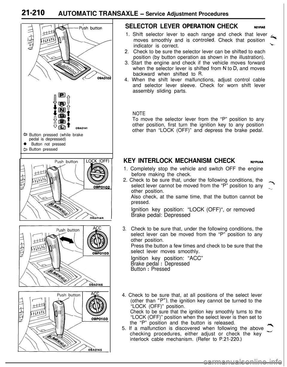
SELECTOR LEVER OPERATlON CHECKNZlFlAE1. Shift selector lever to each range and check that lever
+moves smoothly and is controled. Check that position
indicator is correct.
-L*
2.Check to be sure the selector lever can be shifted to each
position (by button operation as shown in the illustration).
3. Start the engine and check if the vehicle moves forward
when the selector lever is shifted from
N to D, and moves
backward when shifted to
R.4. When the shift lever malfunctions, adjust control cable
and selector lever sleeve. Check for worn shift lever
assembly sliding parts.
NOTETo move the selector lever from the “P” position to any
other position, first turn the ignition key to any position
other than “LOCK (OFF)” and depress the brake pedal.
KEY INTERLOCK MECHANISM CHECKNZlFUAA1. Completely stop the vehicle and switch OFF the engine
before making the check.
2. Check to be sure that, under the following conditions, the
select lever cannot be moved from the “P” position to any
?cother position.
~.‘,Also check, at the same time, that the button cannot be
pressed.Ignition key position:
“LOCK (OFF)“, or removed
Brake pedal: Depressed
3.Check to be sure that, under the following conditions, the
select lever can be moved from the “P” position to any
other position.
Press the button a few times and check to be sure that the
select lever moves smoothly.
Ignition key position: “ACC”
Brake pedal : Depressed
Button
: Pressed4. Check to be sure that, at all positions of the select lever
(other than
“P”), the ignition key cannot be turned to the
“LOCK (OFF)” position.
Check to be sure that the ignition key smoothly turns to the“LOCK (OFF)” position when the select lever is then set to
the “P” position and the button is released.
5. If a malfunction is discovered when following the above
,”checking procedures, either adjust or check the key
interlock cable mechanism. (Refer to
P.21-220.)
Page 1145 of 1216

24-l
HEATERS ANDAIR CONDITIONING
CONTENTSN24M--AIR CONDITIONER SWITCH
..........................30BLOWER ASSEMBLY
.....................................33
COMPRESSOR.................................................37CONDENSER AND CONDENSER FAN
MOTOR............................................................45ENGINE COOLANT TEMPERATURE
-‘-.,SWITCH............................................................51
EVAPORATOR.................................................
34
HEATERCONTROLASSEMBLY....................
26HEATER UNIT
.................................................31
REFRIGERANTLINE........................................47
RESISTOR........................................................29SAFETY PRECAUTIONS
.................................10SERVICE ADJUSTMENT PROCEDURES..
.....11Compressor Drive
Belt Adjustment
.............
23
CompressorNoise........................................24
Handling
TubingandFittings.......................22Idle-up
OperationCheck..............................25Manifold
GaugeSetInstallation..................11Performance Test
.........................................16Power Relay Check
......................................24Refrigerant Leak Repair Procedure
.............17
TestingSystemforLeaks...........................15Test Procedures
...........................................11
SPECIFICATIONS.............................................2
General Specifications..................................2
Lubricants......................................................3Sealant and Adhesives
.................................3Service Specifications
...................................2
TorqueSpecifications...................................2
TROUBLESHOOTING. . . ..a................................3
VENTILATORS(AIR INLET AND AIR OUTLET)
..,....s............. 50
VENTILATORS(INSTRUMENT PANEL)
..,...................*...........49
Page 1155 of 1216
HEATERS AND AIR CONDITIONING - Service Adjustment Procedures 24-I 1
SERVICE ADJUSTMENT PROCEDURES
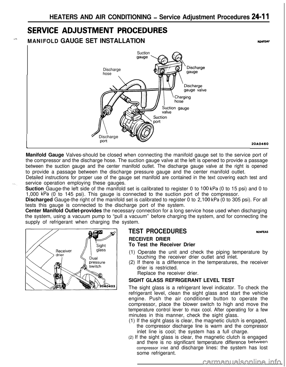
MANIFOLD GAUGE SET INSTALLATION
Suction
gauge
N24FDAF
Discharge
hose
7 Discharge
Port20A0460Manifold Gauge Valves-should be closed when connecting the manifold gauge set to the service port of
the compressor and the discharge hose. The suction gauge valve at the left is opened to provide a passage
between the suction gauge and the center manifold outlet. The discharge gauge valve at the right is openedto provide a passage between the discharge pressure gauge and the center manifold outlet.
Detailed instructions for proper use of the gauge set manifold are contained in the text covering each test andservice operation employing these gauges.
Suction Gauge-the left side of the manifold set is calibrated to register 0 to
100 kPa (0 to 15 psi) and 0 to
1,000
kPa (0 to 145 psi). This gauge is connected to the suction port of the compressor.
Discharged Gauge-the right of the manifold set is calibrated to register 0 to
2,100 kPa (0 to 305 psi). For all
tests this gauge is connected to the discharge port of the system.
Center Manifold Outlet-provides the necessary connection for a long service hose used when discharging
the system, using a vacuum pump to “pull a vacuum”before charging the system, and for connecting the
supply of refrigerant when charging the system.
TEST PROCEDURESN24FEAS
RECEIVER DRIERTo Test the Receiver Drier
(1) Operate the unit and check the piping temperature by
touching the receiver drier outlet and inlet.
(2) If there is a difference in the temperatures, the receiver
drier is restricted.
Replace the receiver drier.
SIGHT GLASS REFRIGERANT LEVEL TEST
The sight glass is a refrigerant level indicator. To check the
refrigerant level, clean the sight glass and start the vehicle
engine. Push the air conditioner button to operate the
compressor, place the blower switch to high and move the
temperature control lever to max cool. After operating for a fewminutes in this manner, check the sight glass.
(1) If the sight glass is clear, the magnetic clutch is engaged,
the compressor discharge line is warm and the compressorinlet line is cool; the system has a full charge.
(2) If the sight glass is clear, the magnetic clutch is engaged
and there is no significant temperature difference between
compressor inlet and discharge lines: the system has lost
some refrigerant.
Page 1156 of 1216
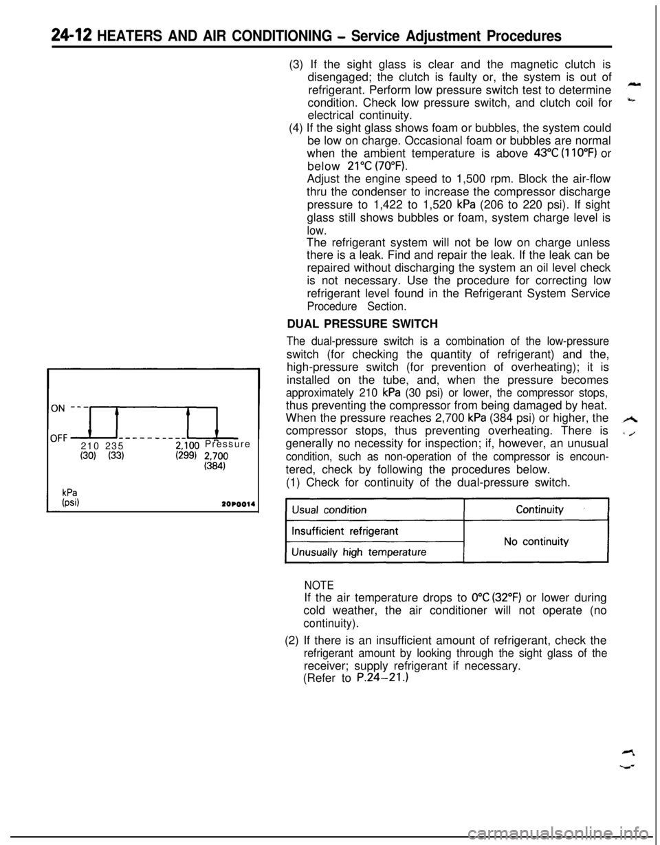
24-12 HEATERS AND AIR CONDITIONING - Service Adjustment Procedures
------__--210 2352,100 Pressure
(30) (33)(299) 2&
kPa(psi)2OPOO14(3) If the sight glass is clear and the magnetic clutch is
disengaged; the clutch is faulty or, the system is out of
refrigerant. Perform low pressure switch test to determine
condition. Check low pressure switch, and clutch coil for
electrical continuity.
(4) If the sight glass shows foam or bubbles, the system could
be low on charge. Occasional foam or bubbles are normal
when the ambient temperature is above
43°C (110°F) or
below
21°C (70°F).Adjust the engine speed to 1,500 rpm. Block the air-flow
thru the condenser to increase the compressor discharge
pressure to 1,422 to 1,520
kPa (206 to 220 psi). If sight
glass still shows bubbles or foam, system charge level is
low.The refrigerant system will not be low on charge unless
there is a leak. Find and repair the leak. If the leak can be
repaired without discharging the system an oil level check
is not necessary. Use the procedure for correcting low
refrigerant level found in the Refrigerant System Service
Procedure Section.DUAL PRESSURE SWITCH
The dual-pressure switch is a combination of the low-pressureswitch (for checking the quantity of refrigerant) and the,
high-pressure switch (for prevention of overheating); it is
installed on the tube, and, when the pressure becomes
approximately 210 kPa (30 psi) or lower, the compressor stops,thus preventing the compressor from being damaged by heat.
When the pressure reaches 2,700
kPa (384 psi) or higher, the
compressor stops, thus preventing overheating. There is
generally no necessity for inspection; if, however, an unusual
condition, such as non-operation of the compressor is encoun-tered, check by following the procedures below.
(1) Check for continuity of the dual-pressure switch.
NOTEIf the air temperature drops to
0°C (32°F) or lower during
cold weather, the air conditioner will not operate (no
continuity).(2) If there is an insufficient amount of refrigerant, check the
refrigerant amount by looking through the sight glass of thereceiver; supply refrigerant if necessary.
(Refer to P.24-21.)