check engine MITSUBISHI ECLIPSE 1991 Service Manual
[x] Cancel search | Manufacturer: MITSUBISHI, Model Year: 1991, Model line: ECLIPSE, Model: MITSUBISHI ECLIPSE 1991Pages: 1216, PDF Size: 67.42 MB
Page 541 of 1216
FUEL SYSTEM - Throttle Bodv <1.8L Engine>
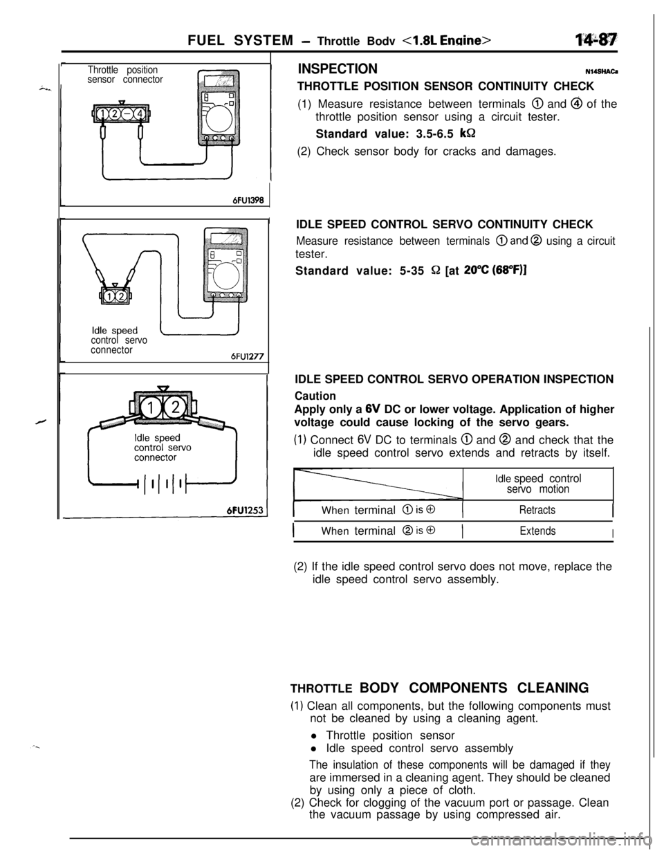
Throttle position
sensor connectorINSPECTIONN14SHAC4
THROTTLE POSITION SENSOR CONTINUITY CHECK
(1) Measure resistance between terminals
@ and @ of the
throttle position sensor using a circuit tester.
Standard value: 3.5-6.5
kSZ(2) Check sensor body for cracks and damages.
6FU1398
I
control servo
connector
6FU1277
IIDLE SPEED CONTROL SERVO OPERATION INSPECTIONIDLE SPEED CONTROL SERVO CONTINUITY CHECK
Measure resistance between terminals @and @ using a circuittester.
Standard value: 5-35
Q [at 20°C (68”F)I
CautionApply only a 6V DC or lower voltage. Application of higher
voltage could cause locking of the servo gears.
(1) Connect 6V DC to terminals @ and @ and check that the
idle speed control servo extends and retracts by itself.
Idle speed controlservo motion
I
IWhen terminal @ is @(RetractsI
IWhen terminal @ is @)ExtendsI(2) If the idle speed control servo does not move, replace the
idle speed control servo assembly.
THROTTLE BODY COMPONENTS CLEANING
(1) Clean all components, but the following components must
not be cleaned by using a cleaning agent.
l Throttle position sensor
l Idle speed control servo assembly
The insulation of these components will be damaged if theyare immersed in a cleaning agent. They should be cleaned
by using only a piece of cloth.
(2) Check for clogging of the vacuum port or passage. Clean
the vacuum passage by using compressed air.
Page 542 of 1216
14-88FUEL SYSTEM - Throttle Body 4.8L Engine>
,
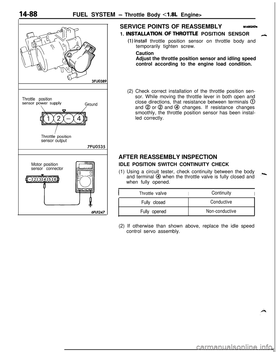
Throttle position
round
sensor output
7FUO535
Motor positionsensor connector
6FU1247SERVICE POINTS OF REASSEMBLYN14SGADa
1. INSTALLATlON.OF THROlTLE POSITION SENSOR
H
(1) Install throttle position sensor on throttle body and
temporarily tighten screw.
Caution
Adjust the throttle position sensor and idling speed
control according to the engine load condition.
(2) Check correct installation of the throttle position sen-
sor. While moving the throttle lever in both open and
close directions, that resistance between terminals
@and
@ or @ and @ changes. If resistance changes
smoothly, the throttle position sensor has been instal-
led correctly.
AFTER REASSEMBLY INSPECTION
IDLE POSITION SWITCH CONTINUITY CHECK
(1) Using a circuit tester, check continuity between the body
and terminal
@I when the throttle valve is fully closed and,riwhen fully opened.
Throttle valveIContinuityI
Fully closed
Fully openedConductive
Non-conductive(2) If otherwise than shown above, replace the idle speed
control servo assembly.
Page 546 of 1216
14-92FUEL SYSTEM- Throttle Bodv <2.0L DOHC Engine>
Iw--
7FUOOl I
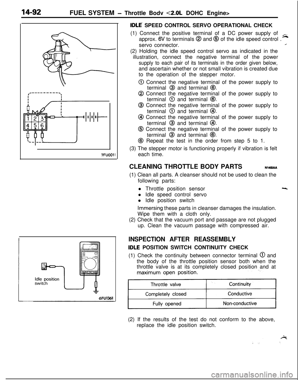
tDLE SPEED CONTROL SERVO OPERATIONAL CHECK
(1) Connect the positive terminal of a DC power supply of
approx.
6V to terminals @ and @ of the idle speed control .
~servo connector.
/(2) Holding the idle speed control servo as indicated in the
illustration, connect the negative terminal of the power
supply to each pair of its terminals in the order given below,and ascertain whether or not small vibration is created due
to the operation of the stepper motor.
0 Connect the negative terminal of the power supply to
terminal
@ and terminal @.
@ Connect the negative terminal of the power supply to
terminal
@ and terminal @I.
@ Connect the negative terminal of the power supply to
terminal
@ and terminal @I.
@I Connect the negative terminal of the power supply to
terminal
@ and terminal @I.
@ Connect the negative terminal of the power supply to
terminal
@ and terminal @.
@ Repeat the test in the order from step 5 to 1.
(3) The stepper motor is functioning properly if vibration is felt
each time.
CLEANING THROTTLE BODY PARTSN14SlAA
(1) Clean all parts. A cleanser should not be used to clean the
following parts:
l Throttle position sensor
l Idle speed control servo
l Idle position switch
Immersing these parts in cleanser damages the insulation.
Wipe them with a cloth only.
(2) Check that the vacuum port and passage are not plugged
up. Clean the vacuum passage with compressed air.
INSPECTION AFTER REASSEMBLY
tDLE POSITION SWITCH CONTINUITY CHECK
(1) Check the continuity between connector terminal
@ and
the body of the throttle position sensor both when the
throttle valve is at its completely closed position and at
maximum open position.
11(2) If the results of the test do not conform to the above,
replace the idle position switch.
Page 552 of 1216
14-98FUEL SYSTEM -Fuel Tank
W636
Positioning projection03AO257
\03A0256SERVICE POINTS OF REMOVAL
N14G6AHl6. DISCONNECTION OF HIGH PRESSURE FUEL
HGSECaution
Cover the hose connection with rags to prevent splash
of fuel that could be caused by some residual pressure
in the fuel pipe line.
INSPECTIONN14GCAHl Check the hoses and the pipes for crack or damage.
l Check the fuel tank cap for malfunction.
l Check the fuel tank for deformation, corrosion or crack.
l Check the fuel tank for dust or foreign material.
NOTE
If the inside of the fuel tank is to be cleaned, use any one ofthe following:
(1) Kerosene
(2) Trichloroethylene
(3) A neutral emulsion type detergent
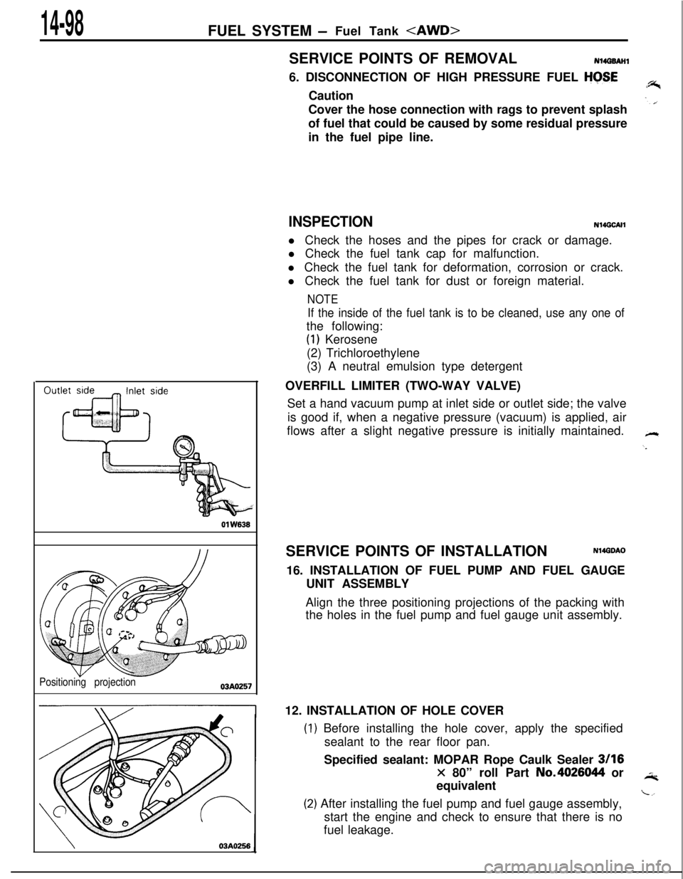
OVERFILL LIMITER (TWO-WAY VALVE)
Set a hand vacuum pump at inlet side or outlet side; the valve
is good if, when a negative pressure (vacuum) is applied, air
flows after a slight negative pressure is initially maintained.
SERVICE POINTS OF INSTALLATION
N14GDAO16. INSTALLATION OF FUEL PUMP AND FUEL GAUGE
UNIT ASSEMBLY
Align the three positioning projections of the packing with
the holes in the fuel pump and fuel gauge unit assembly.
12. INSTALLATION OF HOLE COVER
) Before installing the hole cover, apply the specified
sealant to the rear floor pan.
Specified sealant: MOPAR Rope Caulk Sealer
3116
x 80” roll Part No.4026044 or
equivalent
!) After installing the fuel pump and fuel gauge assembly,
start the engine and check to ensure that there is no
fuel leakage.
Page 560 of 1216
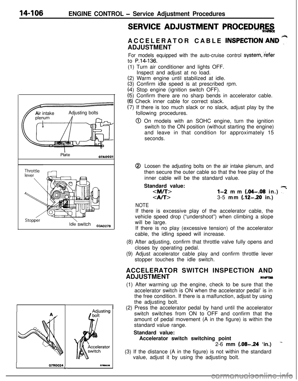
14-106ENGINE CONTROL - Service Adjustment Procedures
TAir intakeAdjusting bolts
Idle switch03A,,2.8
07RQ024L
I
SERVICE ADJUSTMENT PROCEDM%,&ACCELERATOR CABLE
CNSPECTION AN&I ”ADJUSTMENT
For models equipped with the auto-cruise control systemreferto
P.14-136.(1) Turn air conditioner and lights OFF.
Inspect and adjust at no load.
2) Warm engine until stabilized at idle.
3) Confirm idle speed is at prescribed rpm.
4) Stop engine (ignition switch OFF).
5) Confirm there are no sharp bends in accelerator cable.
6) Check inner cable for correct slack.
7) If there is too much slack or no slack, adjust play by the
following procedures.
@ On models with an SOHC engine, turn the ignition
switch to the ON position (without starting the engine)
and leave in that condition for approximately 15
seconds.@
Loosen the adjusting bolts on the air intake plenum, andthen secure the outer cable so that the free play of the
inner cable will be the standard value.
Standard value:
jlr
3-5 mm (.12-.20 in.)
NOTEIf there is excessive play of the accelerator cable, the
vehicle speed drop (“undershoot”) when climbing a slope
will be large.
If there is no play (excessive tension) of the accelerator
cable, the idling speed will increase.
(8) After adjusting, confirm that throttle valve fully opens and
closes by operating pedal.
(9) Adjust accelerator cable play and confirm throttle lever
stopper touches the idle switch.
ACCELERATOR SWITCH INSPECTION AND
ADJUSTMENT
NlWlEB(1) After warming up the engine, check to be sure that the
accelerator switch is ON when the accelerator pedal’ is in
the free condition. If there is a malfunction, adjust by using
the adjusting bolt.
(2) Press the accelerator pedal by hand until the accelerator
switch switches from ON to OFF and confirm that the
amount of pedal movement (A in the figure) is within the
standard value range.
Standard value:
Accelerator switch switching point
2-6 mm
(.08-.24 ‘in.)
(3) If the distance (A in the figure) is not within the standard
value, adjust it by using the adjusting bolt.
Page 562 of 1216
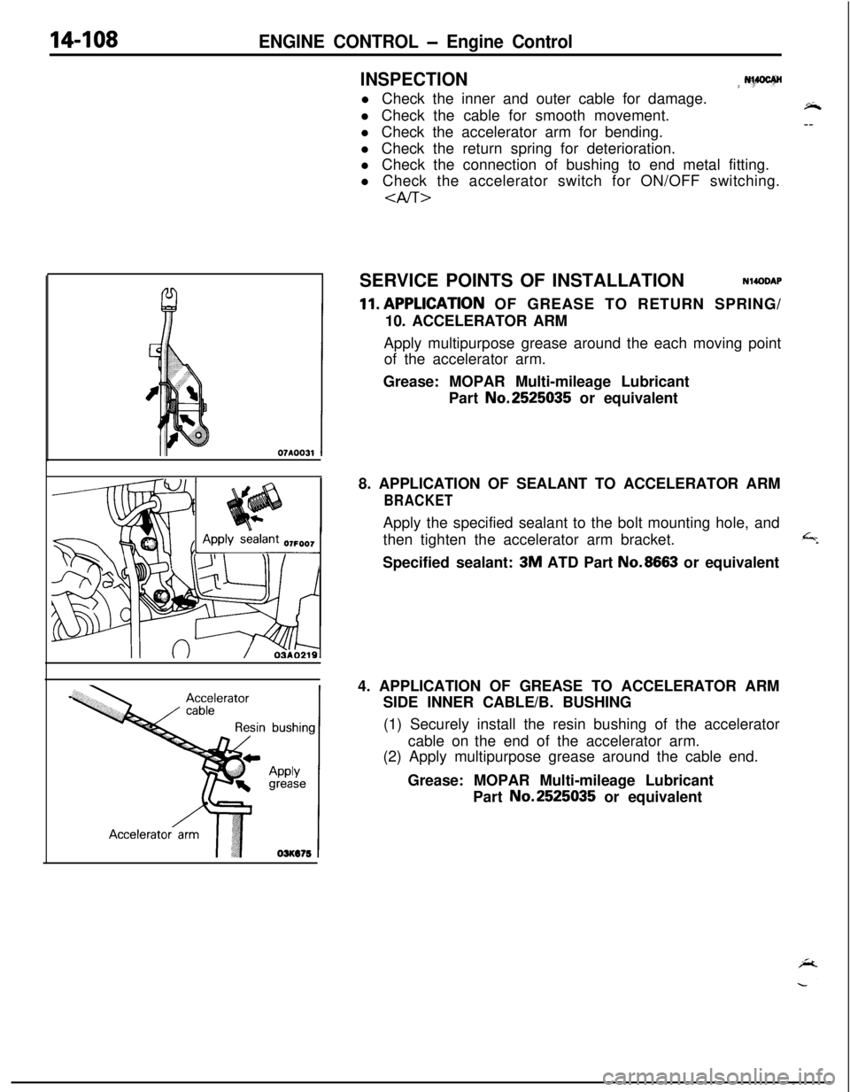
14-108ENGINE CONTROL - Engine Control
INSPECTION
j N%PJCf@l Check the inner and outer cable for damage.
l Check the cable for smooth movement.$+
l Check the accelerator arm for bending.--
l Check the return spring for deterioration.
l Check the connection of bushing to end metal fitting.
l Check the accelerator switch for ON/OFF switching.
SERVICE POINTS OF INSTALLATIONN14DDAP
ll.APPLlCATlON OF GREASE TO RETURN SPRING/
10. ACCELERATOR ARM
Apply multipurpose grease around the each moving point
of the accelerator arm.
Grease: MOPAR Multi-mileage Lubricant
Part No.2525035 or equivalent
8. APPLICATION OF SEALANT TO ACCELERATOR ARM
BRACKETApply the specified sealant to the bolt mounting hole, and
then tighten the accelerator arm bracket.
,%Specified sealant:
3M ATD Part No.8663 or equivalent
4. APPLICATION OF GREASE TO ACCELERATOR ARM
SIDE INNER CABLE/B. BUSHING
(1) Securely install the resin bushing of the accelerator
cable on the end of the accelerator arm.
(2) Apply multipurpose grease around the cable end.
Grease: MOPAR Multi-mileage Lubricant
Part No.2525035 or equivalent
Page 574 of 1216
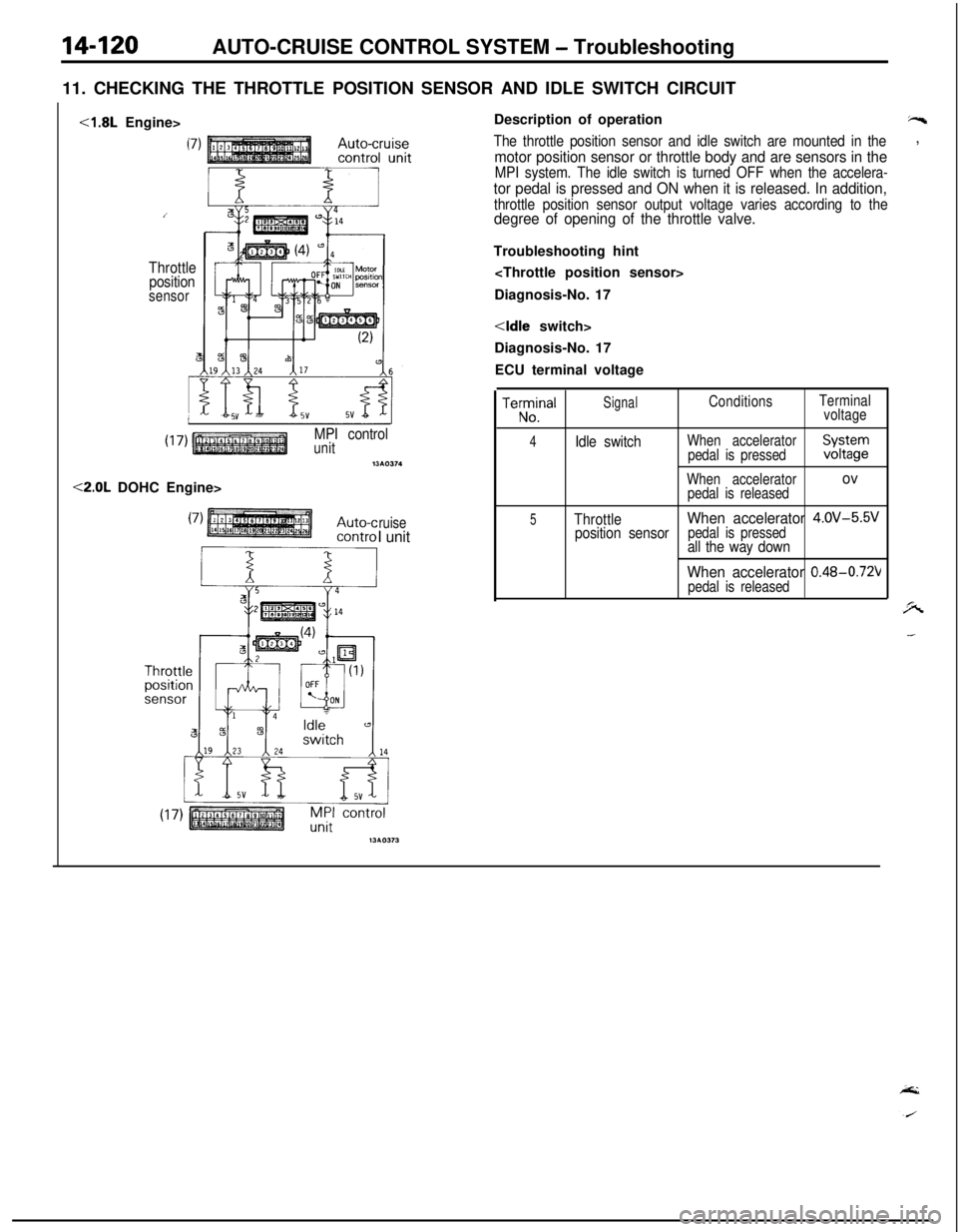
14-120AUTO-CRUISE CONTROL SYSTEM - Troubleshooting
11. CHECKING THE THROTTLE POSITION SENSOR AND IDLE SWITCH CIRCUIT<1.8L Engine>
Throttle
position
sensor
MPI controlunitnw374<2.0L DOHC Engine>
ruiseI unitDescription of operation
“s
The throttle position sensor and idle switch are mounted in the,
motor position sensor or throttle body and are sensors in theMPI system. The idle switch is turned OFF when the accelera-
tor pedal is pressed and ON when it is released. In addition,
throttle position sensor output voltage varies according to thedegree of opening of the throttle valve.Troubleshooting hint
Diagnosis-No. 17
Diagnosis-No. 17
ECU terminal voltageTeKlna’
SignalConditionsTerminal
voltage
4Idle switchWhen accelerator
pedal is pressedXFgr
When acceleratorovpedal is released
5ThrottleWhen accelerator 4.OV-5.5V
position sensorpedal is pressedall the way down
When accelerator 0.48-0.72Vpedal is released
Page 590 of 1216
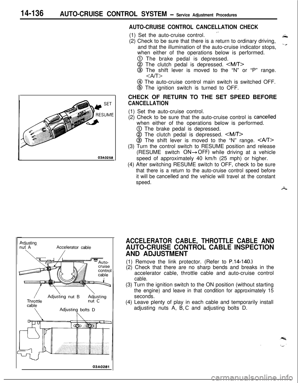
14-136AUTO-CRUISE CONTROL SYSTEM- Service Adjustment Procedures03AQ250
rdjusting
03A0281
AUTO-CRUISE CONTROL CANCELLATION CHECK(1) Set the auto-cruise control.
”(2) Check to be sure that there is a return to ordinary driving,
and that the illumination of the auto-cruise indicator stops,
‘cwhen either of the operations below is performed.
@ The brake pedal is depressed.
@ The clutch pedal is depressed.
@ The shift lever is moved to the “N” or “P” range.
aIT>
@ The auto-cruise control main switch is switched OFF.
@ The ignition switch is turned to OFF.
CHECK OF RETURN TO THE SET SPEED BEFORE
CANCELLATION(1) Set the auto-cruise control.
(2) Check to be sure that the auto-cruise control is
cancelledwhen either of the operations below is performed.
@ The brake pedal is depressed.
@ The clutch pedal is depressed.
@I The shift lever is moved to the “N” range. (3) Turn the control switch to RESUME position and release
(RESUME switch
ONdOFF) while driving at a vehicle
speed of approximately 40 km/h (25 mph) or higher.
(4) After switching RESUME switch to OFF, check to be sure
that there is a return to the auto-cruise control speed before
it will be
cancelled and the vehicle will travel at the constant
speed.
A
ACCELERATOR CABLE, THROTTLE CABLE AND
AUTO-CRUISE CONTROL CABLE INSPECTION
AND ADJUSTMENT(1) Remove the link protector. (Refer to P.14140.)
(2) Check that there are no sharp bends and breaks in the
accelerator cable, throttle cable and auto-cruise control
cable.(3) Turn the ignition switch to the ON position (without starting
the engine) and leave in that condition for approximately 15
seconds.(4) Leave plenty of play in each cable and temporarily install
adjusting nuts A,
B, C and adjusting bolts D.
Page 658 of 1216
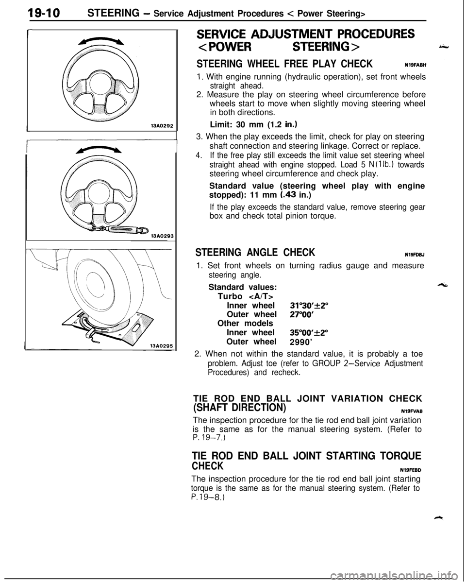
19-10STEERING - Service Adjustment Procedures c Power Steering>
r13A029213A0293
r
1
i
SERVICE ADJUSTMENT PROCEDURES
STEERING WHEEL FREE PLAY CHECKNlSFABH
1. With engine running (hydraulic operation), set front wheels
straight ahead.2. Measure the play on steering wheel circumference before
wheels start to move when slightly moving steering wheel
in both directions.
Limit: 30 mm (1.2
in.13. When the play exceeds the limit, check for play on steering
shaft connection and steering linkage. Correct or replace.
4.If the free play still exceeds the limit value set steering wheel
straight ahead with engine stopped. Load 5
N (1 lb.1 towardssteering wheel circumference and check play.
Standard value (steering wheel play with engine
stopped): 11 mm
I.43 in.)
If the play exceeds the standard value, remove steering gearbox and check total pinion torque.
STEERING ANGLE CHECKN19FDBJ1. Set front wheels on turning radius gauge and measure
steering angle.Standard values:
Turbo
Inner wheel
31”30’+2”Outer wheel
27”OOOther models
Inner wheel
35”00’_+2”Outer wheel
2990’
2. When not within the standard value, it is probably a toe
problem. Adjust toe (refer to GROUP 2-Service Adjustment
Procedures) and recheck.TIE ROD END BALL JOINT VARIATION CHECK
(SHAFT DIRECTION)N19FVA8The inspection procedure for the tie rod end ball joint variation
is the same as for the manual steering system. (Refer to
P. 19-7.)
TIE ROD END BALL JOINT STARTING TORQUE
CHECKNlSFEBDThe inspection procedure for the tie rod end ball joint starting
torque is the same as for the manual steering system. (Refer to
P.19-8.)
Page 659 of 1216
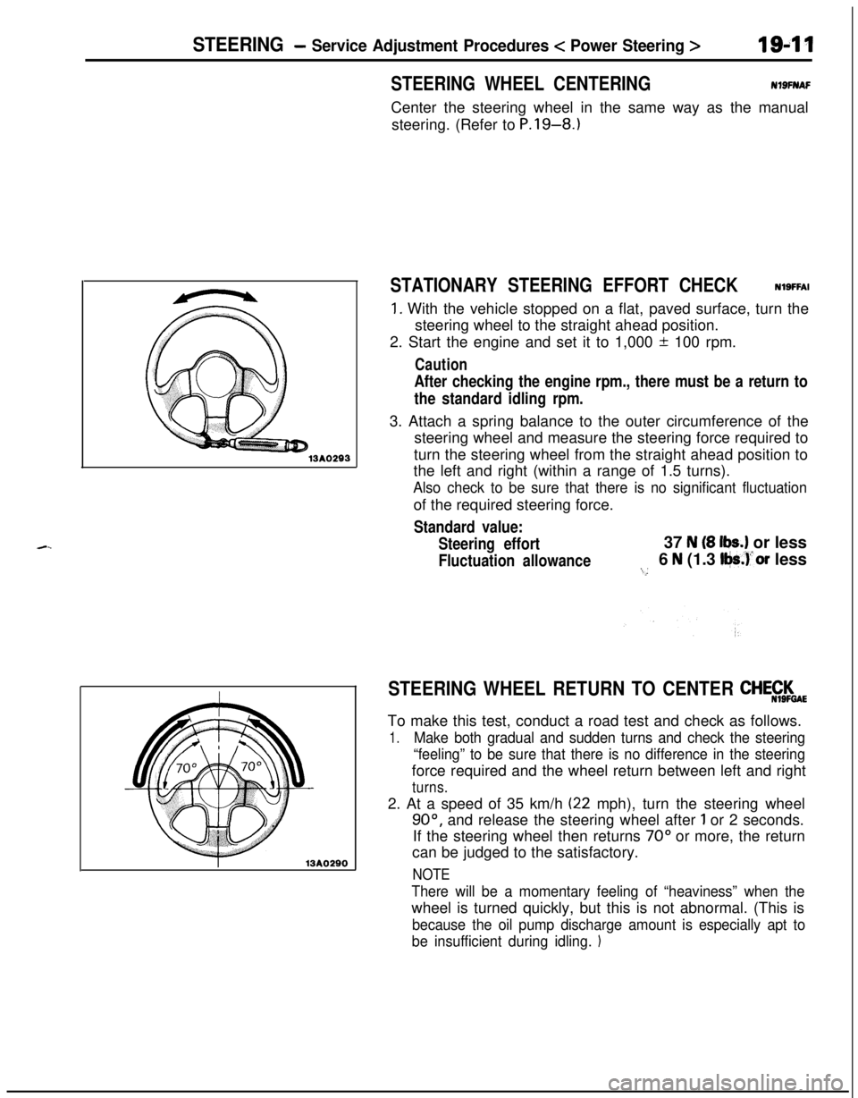
STEERING - Service Adjustment Procedures < Power Steering >194113AO29313AO290
STEERING WHEEL CENTERINGNlSFIYAFCenter the steering wheel in the same way as the manual
steering. (Refer to P.19-8.1
STATIONARY STEERING EFFORT CHECKNlSFFAI
1. With the vehicle stopped on a flat, paved surface, turn the
steering wheel to the straight ahead position.
2. Start the engine and set it to 1,000 + 100 rpm.
Caution
After checking the engine rpm., there must be a return to
the standard idling rpm.3. Attach a spring balance to the outer circumference of the
steering wheel and measure the steering force required to
turn the steering wheel from the straight ahead position to
the left and right (within a range of 1.5 turns).
Also check to be sure that there is no significant fluctuationof the required steering force.
Standard value:
Steering effort37
N (8 lbs.) or less
Fluctuation allowance6 N (1.3 Iljs.)‘or less:...
STEERING WHEEL RETURN TO CENTER CHE$$$aETo make this test, conduct a road test and check as follows.
1.Make both gradual and sudden turns and check the steering
“feeling” to be sure that there is no difference in the steeringforce required and the wheel return between left and right
turns.2. At a speed of 35 km/h
(22 mph), turn the steering wheel
90°, and release the steering wheel after 1 or 2 seconds.
If the steering wheel then returns
70” or more, the return
can be judged to the satisfactory.
NOTE
There will be a momentary feeling of “heaviness” when thewheel is turned quickly, but this is not abnormal. (This is
because the oil pump discharge amount is especially apt to
be insufficient during idling.
1