check engine MITSUBISHI ECLIPSE 1991 Service Manual
[x] Cancel search | Manufacturer: MITSUBISHI, Model Year: 1991, Model line: ECLIPSE, Model: MITSUBISHI ECLIPSE 1991Pages: 1216, PDF Size: 67.42 MB
Page 660 of 1216
19-12STEERING - Service Adjustment Procedures
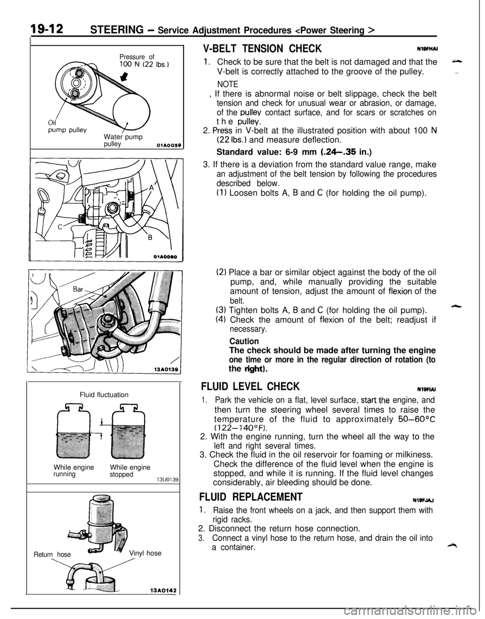
Pressure ofWater pump
pulleyOlA0059Fluid fluctuation
While engine
runningWhile enginestopped13uo139
Return hoseVinyl hose
x ,3Ao,42-
V-BELT TENSION CHECKNlSFliAl
1.Check to be sure that the belt is not damaged and that the
V-belt is correctly attached to the groove of the pulley.
NOTE, If there is abnormal noise or belt slippage, check the belt
tension and check for unusual wear or abrasion, or damage,
of the
pullev contact surface, and for scars or scratches onthe
pulley.2.
Press in V-belt at the illustrated position with about 100 N
(22 Ibs.) and measure deflection.
Standard value: 6-9 mm
1.26.35 in.)
3. If there is a deviation from the standard value range, make
an adjustment of the belt tension by following the procedures
described below.
(1) Loosen bolts A, B and C (for holding the oil pump).
(2) Place a bar or similar object against the body of the oil
pump, and, while manually providing the suitable
amount of tension, adjust the amount of
flexion of the
belt.
(3) Tighten bolts A, B and C (for holding the oil pump).
(4) Check the amount of flexion of the belt; readjust if
necessary.
CautionThe check should be made after turning the engine
one time or more in the regular direction of rotation (tothe
dght).
FLUID LEVEL CHECKNlSFIAI
1.Park the vehicle on a flat, level surface, startthe engine, andthen turn the steering wheel several times to raise the
temperature of the fluid to approximately
50-60°C
(122-140°F).2. With the engine running, turn the wheel all the way to the
left and right several times.3. Check the fluid in the oil reservoir for foaming or milkiness.
Check the difference of the fluid level when the engine is
stopped, and while it is running. If the fluid level changes
considerably, air bleeding should be done.
FLUID REPLACEMENTNlSFJAJ
1.Raise the front wheels on a jack, and then support them with
rigid racks.2. Disconnect the return hose connection.
3.Connect a vinyl hose to the return hose, and drain the oil into
a container.
Page 661 of 1216
STEERING - Service -Adjustment Procedures < Power Steering >IgJf~
4.Disconnect the high-tension cable, and then while operating
the starting motor intermittently, turn the steering wheel all;
the way to the left and right several times to drain all of the
fluid.
Caution, 35
Be careful not to position thq high-tension able ye&r the
carburetor or the delivery pipe.5. Connect the return hoses securely, and then
secur& it ,with
the clip.6. Fill the oil reservoir with the specified fluid up
td the Ibwerposition of the filter, and then bleed the air.
.’
Specified fluid:MOPAR ATF PLUS (Automatic Transmis-sion Fluid Type 7176)/Automatic trans-
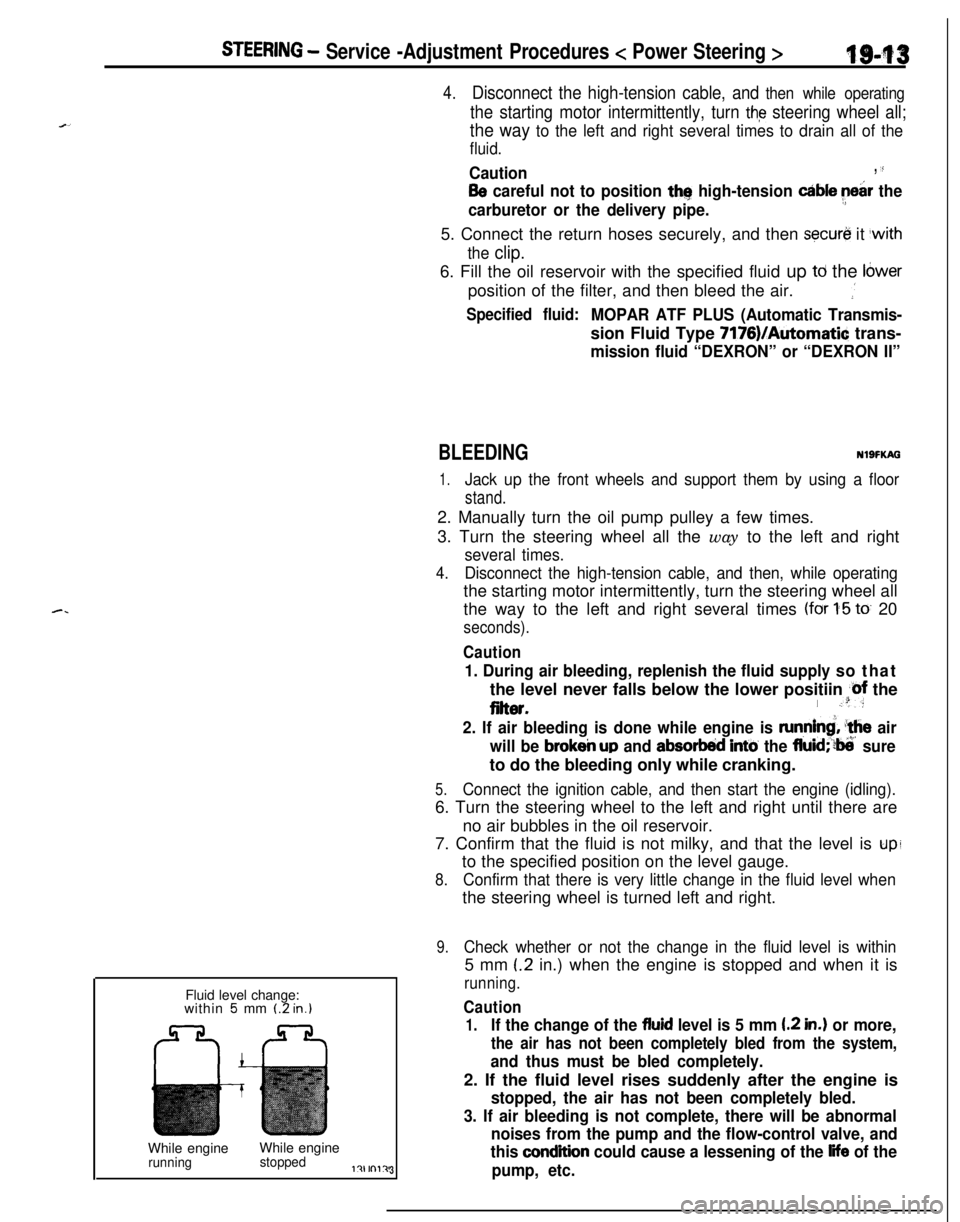
mission fluid “DEXRON” or “DEXRON II”Fluid level change:
within
5 mm (2 in.)While engineWhile engine
runningstoppedl?lrnl?J3
BLEEDINGNlSFKAG
1.Jack up the front wheels and support them by using a floor
stand.2. Manually turn the oil pump pulley a few times.
3. Turn the steering wheel all the way to the left and right
several times.
4.Disconnect the high-tension cable, and then, while operatingthe starting motor intermittently, turn the steering wheel all
the way to the left and right several times
(for 1-5 to 20
seconds).
Caution
1. During air bleeding, replenish the fluid supply so thatthe level never falls below the lower positiin
@f the
eiter.I .“:
2. If air bleeding is done while engine is runnind, ‘the air
will be
brokeir up and absorbed intti the fluid;‘?ti’ sureto do the bleeding only while cranking.
5.Connect the ignition cable, and then start the engine (idling).6. Turn the steering wheel to the left and right until there are
no air bubbles in the oil reservoir.
7. Confirm that the fluid is not milky, and that the level is
upito the specified position on the level gauge.
8.Confirm that there is very little change in the fluid level whenthe steering wheel is turned left and right.
9.Check whether or not the change in the fluid level is within5 mm
(.2 in.) when the engine is stopped and when it is
running.
Caution
1.If the change of the fluid level is 5 mm I.2 in.) or more,
the air has not been completely bled from the system,
and thus must be bled completely.2. If the fluid level rises suddenly after the engine is
stopped, the air has not been completely bled.
3. If air bleeding is not complete, there will be abnormal
noises from the pump and the flow-control valve, and
this
condition could cause a lessening of the life of the
pump, etc.
Page 662 of 1216
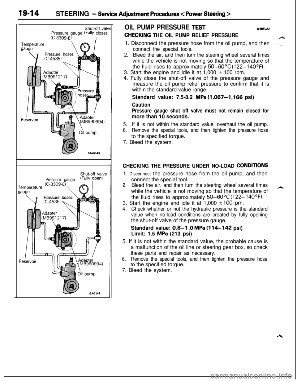
19-14STEERING - Service Adjustment Procedures < Power Steering >Shut-off valv
Pressure gauge
(FW close)
(C-3309-E)I
Temperature
gauge
\e’\
Pressure hoses
Re(Mti990994)
\Oil pump
713AO145Shut-off valve
Pressure gauge(FullY ?penl
Pressure hoses
OIL PUMP PRESSURE TESTNl9FlAF
CHECKING THE OIL PUMP RELIEF PRESSURE1. Disconnect the pressure hose from the oil pump, and then
connect the special tools.
2.Bleed the air, and then turn the steering wheel several timeswhile the vehicle is not moving so that the temperature of
the fluid rises to approximately
50-60°C (122-14OOF).3. Start the engine and idle it at 1,000
f 100 rpm.
4. Fully close the shut-off valve of the pressure gauge and
measure the oil pump relief pressure to confirm that it is
within the standard value range.
Standard value: 7.5-8.2
MPa (1,067-1,166 psi)
Caution
Pressure gauge shut off valve must not remain closed formore than 10 seconds.
5.If it is not within the standard value, overhaul the oil pump.
6.Remove the special tools, and then tighten the pressure hoseto the specified torque.
7. Bleed the system.
CHECKING THE PRESSURE UNDER NO-LOAD CONDITIONS1. Disconnect the pressure hose from the oil pump, and then
connect the special tool.
2.Bleed the air, and then turn the steering wheel several timeswhile the vehicle is not moving so that the temperature of
the fluid rises to approximately
50-60°C (122-14OOF).3. Start the engine and idle it at 1,000
-t 100 rpm.
4.
Check whether or not the hydraulic pressure is the standard
value when no-load conditions are created by fully openingthe shut-off valve of the pressure gauge.
Standard value:
0.8-I .O MPa (114-142 psi)
Limit: 1.5
MPa (213 psi)
5. If it is not within the standard value, the probable cause is
a malfunction of the oil line or steering gear box, so check
these parts and repair as necessary.
6.Remove the special tools, and then tighten the pressure hoseto the specified torque.
7. Bleed the system.
Page 663 of 1216
-
c. .
STEERING - Service Adiustment Procedures
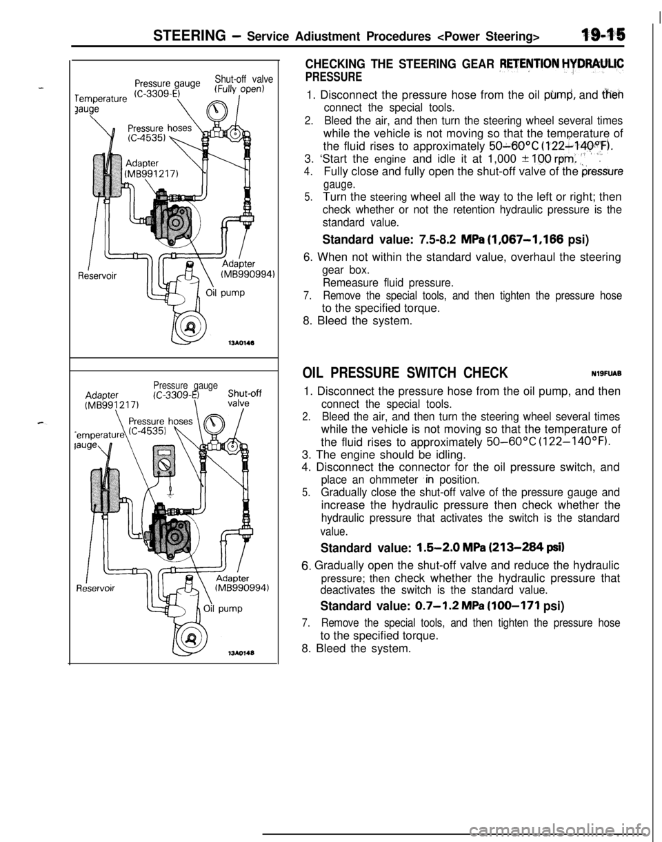
Shut-off valve
Pressure gauge
CHECKING THE STEERING GEAR PETENTION HYDRAULIC
PRESSURE1. Disconnect the pressure hose from the oil
pbmd, and iheh
connect the special tools.
2.Bleed the air, and then turn the steering wheel several timeswhile the vehicle is not moving so that the temperature of
the fluid rises to approximately
50~60OC (122~14pyF).
3. ‘Start the engine and idle it at 1,000 +
100 rem: .‘,’.
4.Fully close and fully open the shut-off valve of the pressure
gauge.
5.Turn the steering wheel all the way to the left or right; then
check whether or not the retention hydraulic pressure is the
standard value.
Standard value: 7.5-8.2 MPa (1,067-1,166 psi)6. When not within the standard value, overhaul the steering
gear box.
Remeasure fluid pressure.
7.Remove the special tools, and then tighten the pressure hoseto the specified torque.
8. Bleed the system.
OIL PRESSURE SWITCH CHECKNlSFUAB1. Disconnect the pressure hose from the oil pump, and then
connect the special tools.
2.Bleed the air, and then turn the steering wheel several timeswhile the vehicle is not moving so that the temperature of
the fluid rises to approximately
50-60°C (122-14OOF).3. The engine should be idling.
4. Disconnect the connector for the oil pressure switch, and
place an ohmmeter ,in position.
5.Gradually close the shut-off valve of the pressure gauge andincrease the hydraulic pressure then check whether the
hydraulic pressure that activates the switch is the standard
value.
Standard value: 1.5-2.0 MPa (213-284 psi)
6. Gradually open the shut-off valve and reduce the hydraulic
pressure; then check whether the hydraulic pressure that
deactivates the switch is the standard value.
Standard value: 0.7-1.2 MPa (100-171 psi)
7.Remove the special tools, and then tighten the pressure hoseto the specified torque.
8. Bleed the system.
Page 687 of 1216
STEERING - Power Steering Oil Pump1849
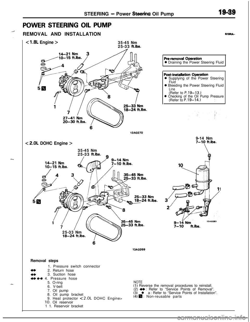
POWER STEERING OIL PUMP
“@REMOVAL AND INSTALLATION
< 1.8L Engine >35-45 Nm25-33 ft.lbs.
20-30 ft.lbs.
13A0270
< 2.0L DOHC Engine >
35-45 Nm25-33 ft.lbs./
NlgRA-
Pre-removal Operation0 Draining the Power Steering Fluid
‘/1
7
25-33 Nm18-24 ft.lbs.
35-45 Nm
Post-installation Operation0 Supplying of the Power Steering
Fluid0 Bleeding the Power Steering Fluid
Line(Refer to P.79-13.)0 Checking of the Oil Pump Pressure(Refer to P.l9-14.)~
9-14 Nm
7-10 ft.lbs.
\
1
9-14 Nm7-10 ft.lbs.
13AO269
Removal steps1. Pressure switch connector
a*2. Return hose
4*3. Suction hose+r) .+ 4. Pressure hose
5. O-ring
6. V-belt
7. Oil pump
8. Oil pump bracket
9. Heat protector
<2.0L DOHC Engine>10. Oil reservoir
1 1. Reservoir bracket
NOTE(I) Reverse the removal procedures to reinstall.
(2) *I) : Refer to “Service Points of Removal”.(3) l a : Refer to “Service Points of Installation”.(4) 0 : Non-reusable parts
Page 688 of 1216
1 S-40STEERING - Power Steering Oil Pump
SERVICE POINTS OF REMOVAL
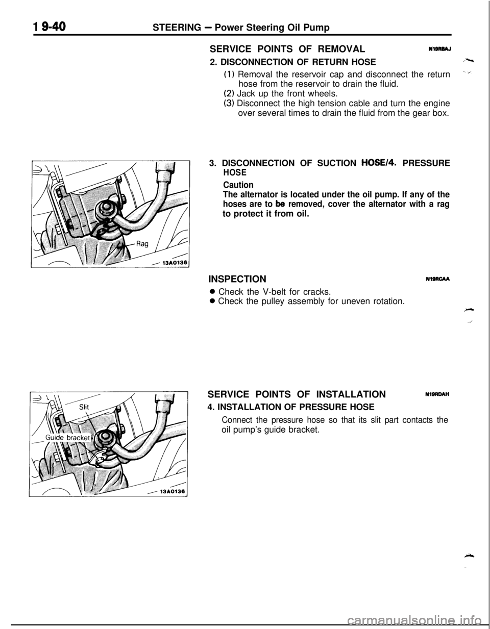
Nl8RW2. DISCONNECTION OF RETURN HOSE
(1) Removal the reservoir cap and disconnect the return
hose from the reservoir to drain the fluid.
(2) Jack up the front wheels.
(3) Disconnect the high tension cable and turn the engine
over several times to drain the fluid from the gear box.
3. DISCONNECTION OF SUCTION
HOSE14. PRESSURE
HOSE
Caution
The alternator is located under the oil pump. If any of the
hoses are to
be removed, cover the alternator with a ragto protect it from oil.
INSPECTION
NIRCAA0 Check the V-belt for cracks.0 Check the pulley assembly for uneven rotation.
SERVICE POINTS OF INSTALLATION
4. INSTALLATION OF PRESSURE HOSE
NlSRDAH
Connect the pressure hose so that its slit part contacts theoil pump’s guide bracket.
Page 713 of 1216
MANUAL TRANSAXLE
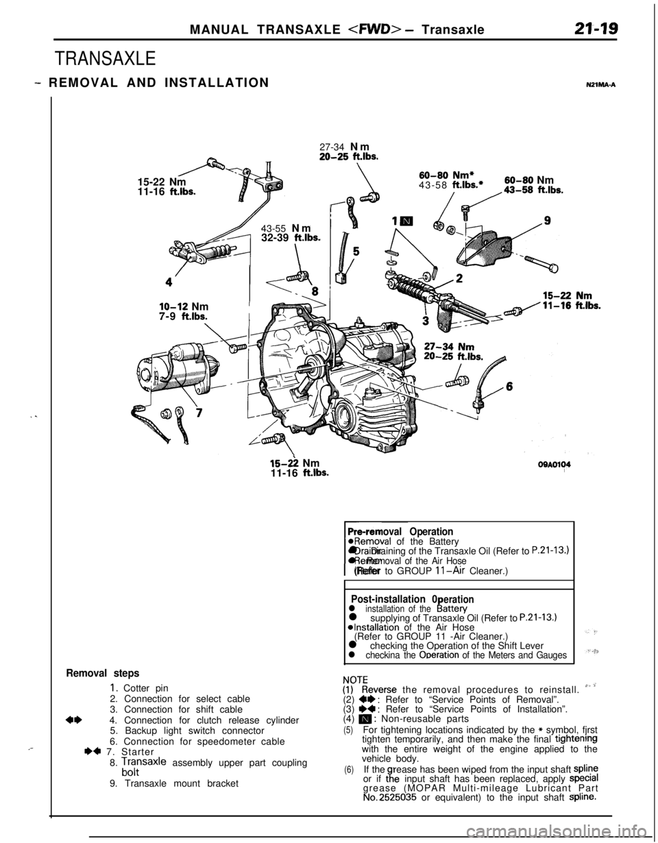
TRANSAXLE
- REMOVAL AND INSTALLATIONNZlMA-A
. .
,-27-34 Nm
20-25 ft.lbs.15-22 Nm
11-16
ft.lbs.43-55 Nm
32-39
ft.lbs.
\
60-80 Nm*43-58 ft.lbs.*60-80 Nm
/da-,, ft.lbs.
lo-12 NmI7-9
ft.lbs.I
15-2: Nm
11-16 ft.lbs.OOAOl~4
Pre-removal Operation@Removal of the Battery
rl Draining of the Transaxle Oil (Refer to
P.21-13.)l Removal of the Air Hose(Refer to GROUP 11-Air Cleaner.)
Post-installation 0erationl installation of theI!attery
l supplying of Transaxle Oil (Refer to P.21-13.)*Installation of the Air Hose
(Refer to GROUP 11 -Air Cleaner.)
l checking the Operation of the Shift Lever
l checkina the Ooeration of the Meters and Gauges
Removal steps
1. Cotter pin
2. Connection for select cable
3. Connection for shift cable
4*4. Connection for clutch release cylinder
5. Backup light switch connector
6. Connection for speedometer cable
I)* 7. Starter
8.
Lfrsaxle assembly upper part coupling
9. Transaxle mount bracket
ZKeverse the removal procedures to reinstall. ” ’(2) W : Refer to “Service Points of Removal”.
(3) ~~ : Refer to “Service Points of Installation”.
(4) m : Non-reusable parts
(5)For tightening locations indicated by the * symbol, fjrst
tighten temporarily, and then make the final tightenrngwith the entire weight of the engine applied to the
vehicle body.
(6)If therease has been wiped from the input shaft spline
or if taeinput shaft has been replaced, apply specralgrease (MOPAR Multi-mileage Lubricant Part
No.2525035 or equivalent) to the input shaft Spline.
Page 776 of 1216
21-82MANUAL TRANSAXLE
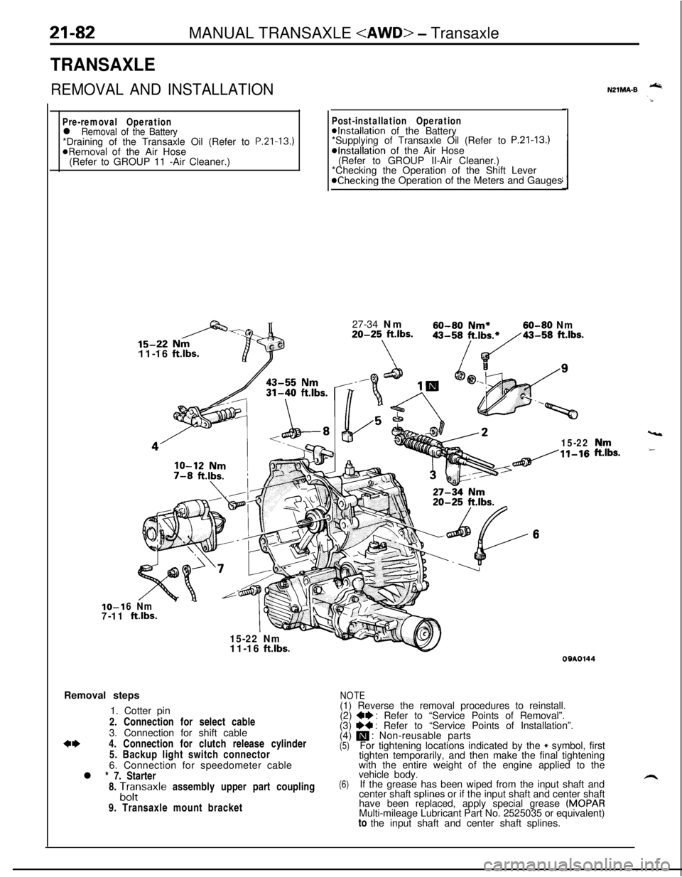
TRANSAXLE
REMOVAL AND INSTALLATION
Pre-removal Operationl Removal of the Battery*Draining of the Transaxle Oil (Refer to P.Zl-13.)
@Removal of the Air Hose
(Refer to GROUP 11 -Air Cleaner.)IO-1
7-1111-16
ftlbs.
Post-installation Operation@Installation of the Battery
*Supplying of Transaxle Oil (Refer to P.21-13.)*Installation of the Air Hose
(Refer to GROUP II-Air Cleaner.)
*Checking the Operation of the Shift Lever
@Checking the Operation of the Meters and Gauges
27-34 Nm
60-60 Nm*60-80 Nm20-25 ft.lbs.
\
43-58/t.,b~43-58 ft.lbs.
15-22
6 Nm
ftlbs.
15-22 Nm
vt11-16
ft.lbs.Removal steps
1. Cotter pin
2. Connection for select cable
3. Connection for shift cable
*I)4. Connection for clutch release cylinder
5. Backup light switch connector
6. Connection for speedometer cable
l * 7. Starter
8.
A;;saxle assembly upper part coupling
9. Transaxle mount bracket
NZlMA-B -
,“rr,s.
09AOl44
NOTE(1) Reverse the removal procedures to reinstall.
(2)
+e : Refer to “Service Points of Removal”.
(3) I)+ : Refer to “Service Points of Installation”.
(4) m : Non-reusable parts(5)For tightening locations indicated by the * symbol, first
tighten temporarily, and then make the final tightening
with the entire weight of the engine applied to the
(6)vehicle body.
If the grease has been wiped from the input shaft and
center shaft splines or if the input shaft and center shaft
have been replaced, apply special grease
(MOPARMulti-mileage Lubricant Part No. 2525035 or equivalent)
to the input shaft and center shaft splines.
Page 860 of 1216
21-166AUTOMATIC TRANSAXLE - SDecifications
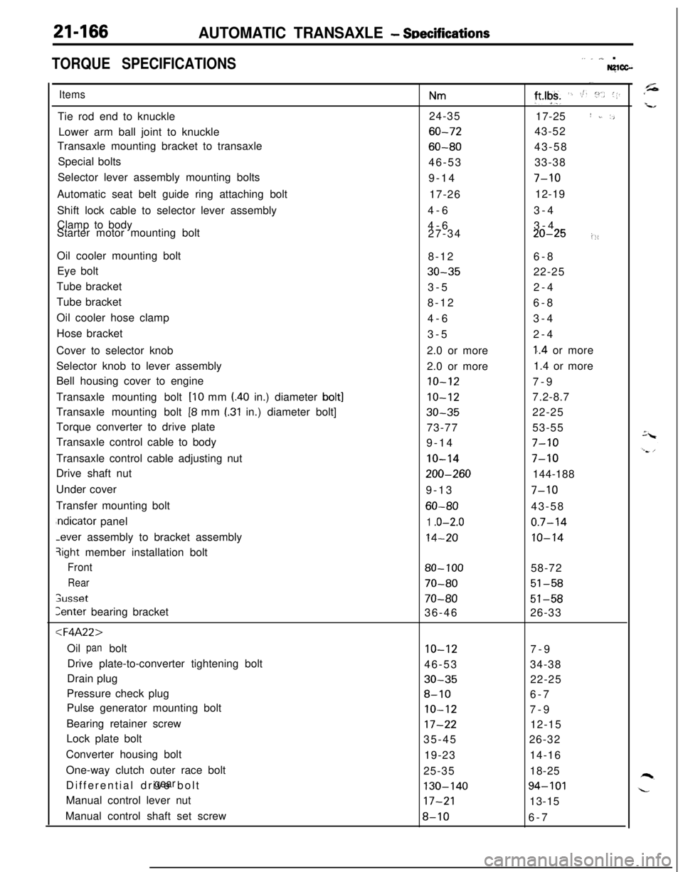
TORQUE SPECIFICATIONS,. _ ,,,_ .Nglcc-
ItemsTie rod end to knuckle
Lower arm ball joint to knuckle
Transaxle mounting bracket to transaxle
Special bolts
Selector lever assembly mounting bolts
Automatic seat belt guide ring attaching bolt
Shift lock cable to selector lever assembly
Clamp to body
Starter motor mounting bolt
Oil cooler mounting bolt
Eye bolt
Tube bracket
Tube bracket
Oil cooler hose clamp
Hose bracket
Cover to selector knob
Selector knob to lever assembly
Bell housing cover to engine
Transaxle mounting bolt
[lo mm l.40 in.) diameter bolt]Transaxle mounting bolt
[8 mm I.31 in.) diameter bolt]
Torque converter to drive plate
Transaxle control cable to body
Transaxle control cable adjusting nut
Drive shaft nut
Under cover
Transfer mounting boltndicator panel-ever assembly to bracket assembly
3ight member installation bolt
Front
Rear
;usset
Zenter bearing bracket
:l=4A22>Oil bolt
panDrive plate-to-converter tightening bolt
Drain plug
Pressure check plug
Pulse generator mounting bolt
Bearing retainer screw
Lock plate bolt
Converter housing bolt
One-way clutch outer race bolt
Differential drive bolt
gearManual control lever nut
Manual control shaft set screw
Nm24-35
60-72
60-8046-53
9-14
17-26
4-6
4-6
27-34
8-12
30-353-5
8-12
4-6
3-5
2.0 or more
2.0 or more
10-12
10-12
30-3573-77
9-14
IO-14
200-2609-13
60-80
1 .o-2.0
14-20
80- 100
70-80
70-8036-46
10-1246-53
30-35
8-10
IO-12
17-2235-45
19-23
25-35
130-14017-21
8-10
-.
ft*lgk+ ‘. St. :“.. (1.17-25
I ~. ‘,43-52
43-58
33-38
7-1012-19
3-4
3-4
20-25i::6-8
22-25
2-4
6-8
3-4
2-4
1..4 or more
1.4 or more
7-9
7.2-8.7
22-25
53-55
7-10
7-10144-188
7-1043-58
0.7-14
10-1458-72
51-58
51-5826-33
7-9
34-38
22-25
6-7
7-9
12-15
26-32
14-16
18-25
94-10113-15
6-7
Page 869 of 1216
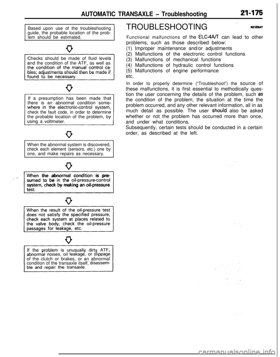
AUTOMATIC TRANSAXLE - TroubleshootingBased upon use of the troubleshooting
guide, the probable location of the prob-
lem should be estimated.
Checks should be made of fluid levels
and the condition of the ATF, as well as
bles; adjustments should then be made if
If a presumption has been made that
there is an abnormal condition some-
check the fault code, in order to determinethe probable location of the problem, by
When the abnormal system is discovered,
check each element (sensors, etc.) one byone, and make repairs as necessary.
“~^II_When the abnormal condition is pre-
sumed to be in the
orI-pressure-controlsystem, check by making an oil-pressure
If the problem is unusually dirty ATF,
of the clutch or brakes, or an abnormal
condition of the transaxle itself,
disassem-TROUBLESHOOTING
”N21EeAYFunctional malfunctions of the ELC4A/T can lead to other
problems, such as those described below:
(1) Improper maintenance and/or adjustments
(2) Malfunctions of the electronic control functions
(3) Malfunctions of mechanical functions
(4) Malfunctions of hydraulic control functions
(5) Malfunctions of engine performance
etc.In order to properly determine (“Troubleshoot”) the source of
these malfunctions, it is first essential to methodically ques-
tion the user concerning the details of the problem, such qs
the condition of the problem, the situation at the time the
problem occurred, and any other relevant information, all in as
much detail as possible. The user
shoutd also be asked
whether or not the problem has occurred more than once,
and under what conditions.
Subsequently, certain tests should be conducted in a certain
order, as described at the left.