check engine MITSUBISHI ECLIPSE 1991 Service Manual
[x] Cancel search | Manufacturer: MITSUBISHI, Model Year: 1991, Model line: ECLIPSE, Model: MITSUBISHI ECLIPSE 1991Pages: 1216, PDF Size: 67.42 MB
Page 1157 of 1216
HEATERS AND AIR CONDITIONING - Service Adjustment Procedures 249*I3
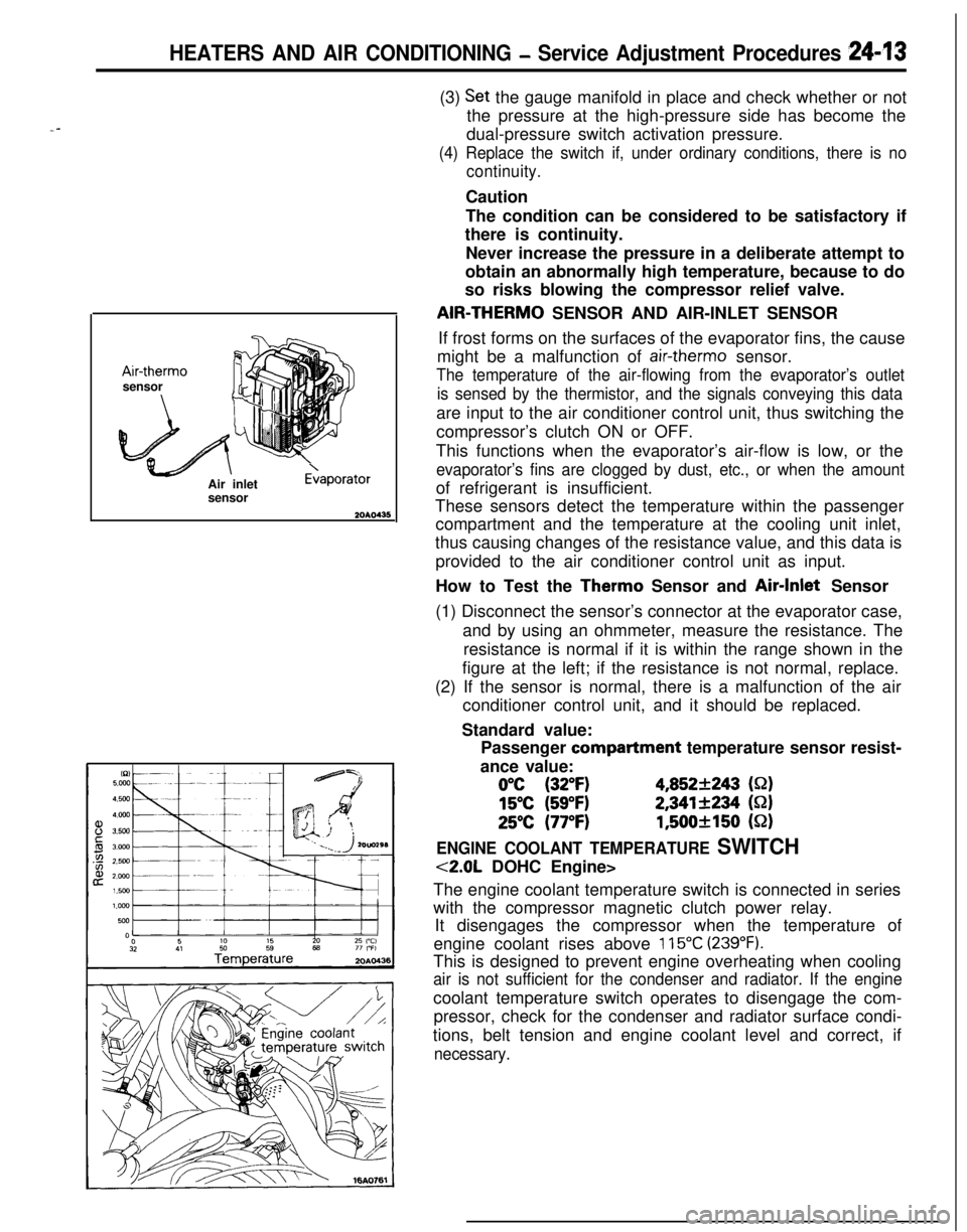
--Air-therm0
sensor
Air inlet
sensor
E>aporator(3)
Set the gauge manifold in place and check whether or not
the pressure at the high-pressure side has become the
dual-pressure switch activation pressure.
(4) Replace the switch if, under ordinary conditions, there is no
continuity.Caution
The condition can be considered to be satisfactory if
there is continuity.
Never increase the pressure in a deliberate attempt to
obtain an abnormally high temperature, because to do
so risks blowing the compressor relief valve.AIR-THERM0 SENSOR AND AIR-INLET SENSOR
If frost forms on the surfaces of the evaporator fins, the cause
might be a malfunction of
air-therm0 sensor.
The temperature of the air-flowing from the evaporator’s outlet
is sensed by the thermistor, and the signals conveying this dataare input to the air conditioner control unit, thus switching the
compressor’s clutch ON or OFF.
This functions when the evaporator’s air-flow is low, or the
evaporator’s fins are clogged by dust, etc., or when the amountof refrigerant is insufficient.
These sensors detect the temperature within the passenger
compartment and the temperature at the cooling unit inlet,
thus causing changes of the resistance value, and this data is
provided to the air conditioner control unit as input.
How to Test the Therm0 Sensor and Air-Inlet Sensor
(1) Disconnect the sensor’s connector at the evaporator case,
and by using an ohmmeter, measure the resistance. The
resistance is normal if it is within the range shown in the
figure at the left; if the resistance is not normal, replace.
(2) If the sensor is normal, there is a malfunction of the air
conditioner control unit, and it should be replaced.
Standard value:
Passenger compartment temperature sensor resist-
ance value:
0°C (32°F)4,852+243 (S-2)
15°C (59°F)2,341+234 (S-2)
25°C (77°F)1,500+150 (52)
ENGINE COOLANT TEMPERATURE SWITCH
<2.0L DOHC Engine>
The engine coolant temperature switch is connected in series
with the compressor magnetic clutch power relay.
It disengages the compressor when the temperature of
engine coolant rises above
115°C (239°F).This is designed to prevent engine overheating when cooling
air is not sufficient for the condenser and radiator. If the enginecoolant temperature switch operates to disengage the com-
pressor, check for the condenser and radiator surface condi-
tions, belt tension and engine coolant level and correct, if
necessary.
Page 1162 of 1216
24-18 HEATERS AND AIR CONDITIONING - Service Adjustment Procedures
(5) Screw a can of R-12 to the opened manifold valve. Be sure
gasket is in place and in good condition. Tighten refrigerantcan and manifold locking nut to insure a good seal. Do not
overtighten 8 to
11 Nm (6 to 8 ft.lbs.) is sufficient if gasket
is in good condition.
(6) Turn manifold valve (above the refrigerant can) completely
clockwise to puncture the can. This closes the valve and
seals the refrigerant in the can.
Caution
Never heat small cans of refrigerant over
40°C (104°F)as they may explode.
(7) Place the refrigerant in a large pan of water heated to 52°C
(104°F). Place pan of water containing the refrigerant can
on an accurate scale so the amount of refrigerant added
can be weighed. Open the refrigerant manifold valve.
(8) Purge all air from test hoses. Air in the system will be
trapped in the condenser causing abnormally high dis-
charge pressures and interfering with condensing of the
refrigerant.(9) Slightly loosen both test hoses at the gauge set manifold.
Tighten the hoses as soon as the air is purged.
(10)Slightly loosen charging hose connection at gauge set
manifold. This will purge air from the charging hose.
Tighten connection as soon as air is purged.
(I l)With vehicle windows open and hood up, operate engine at1,500 rpm and jump the low pressure switch terminals
located on the receiver drier so the clutch will remain
engaged.
(12)Place air conditioner control on air conditioner and place theblower switch on high.
(13)lf necessary, block the condenser to maintain a discharge
pressure of 1,422 to 1,520
kPa (206 to 220 psi). System
must be charged through the evaporator suction service
ports as follows:
(a) Slowly open the suction service gauge valve.
Meter flow of refrigerant by adjusting, the suciton
service gauge valve so that pressure registered at the
suction service gauge does not exceed 345 kPa (50 psi).Keep refrigerant container upright.
(b) Add refrigerant gas until there is no foam visible at the
sight glass.
Add an additional
170 g (6 oz.)
(c) Close the suction gauge valve.
CautionToo much refrigerant in the system can cause
abnormally high discharge pressures. Care must beused so that the exact recommended amount or
refrigerant is added after foam clears in the sight
glass.(d) Close dispensing manifold valve. Remove test hoses
and adapters from the service ports of compressor,
install protective caps at service ports and reconnect
wiring.(e) Check system performance.
(P.24- 16.)
e
. i”
A
i-4
Page 1167 of 1216
HEATERS AND AIR CONDITIONING - Service Adiustment Procedures 24-23
<
we2ouo2er
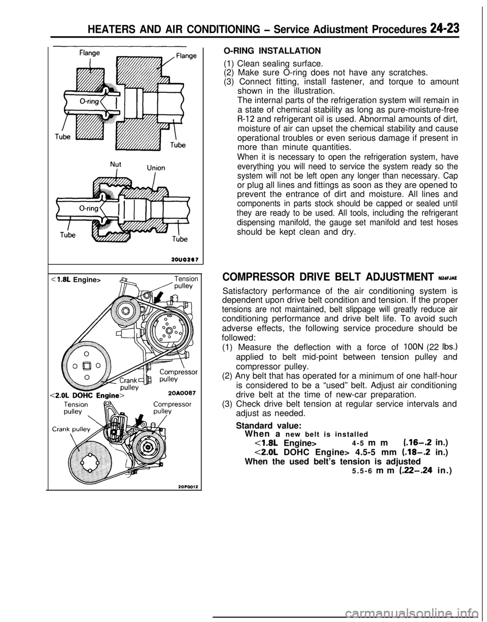
< 1.8L Engine>Tension/ wllevO-RING INSTALLATION
(1) Clean sealing surface.
(2) Make sure O-ring does not have any scratches.
(3) Connect fitting, install fastener, and torque to amount
shown in the illustration.
The internal parts of the refrigeration system will remain in
a state of chemical stability as long as pure-moisture-free
R-12 and refrigerant oil is used. Abnormal amounts of dirt,
moisture of air can upset the chemical stability and cause
operational troubles or even serious damage if present in
more than minute quantities.
When it is necessary to open the refrigeration system, have
everything you will need to service the system ready so the
system will not be left open any longer than necessary. Capor plug all lines and fittings as soon as they are opened to
prevent the entrance of dirt and moisture. All lines and
components in parts stock should be capped or sealed until
they are ready to be used. All tools, including the refrigerant
dispensing manifold, the gauge set manifold and test hosesshould be kept clean and dry.
COMPRESSOR DRIVE BELT ADJUSTMENT N24FJAESatisfactory performance of the air conditioning system is
dependent upon drive belt condition and tension. If the proper
tensions are not maintained, belt slippage will greatly reduce airconditioning performance and drive belt life. To avoid such
adverse effects, the following service procedure should be
followed:
(1) Measure the deflection with a force of
IOON (22 Ibs.)applied to belt mid-point between tension pulley and
compressor pulley.
(2) Any belt that has operated for a minimum of one half-hour
is considered to be a “used” belt. Adjust air conditioning
drive belt at the time of new-car preparation.
(3) Check drive belt tension at regular service intervals and
adjust as needed.
Standard value:
When a new belt is installed<1.8L Engine>4-5 mm
(.16-.2 in.)
<2.0L DOHC Engine> 4.5-5 mm (.18-.2 in.)
When the used belt’s tension is adjusted
5.5-6 mm
(.22-.24 in.)
Page 1168 of 1216
24-24 HEATERS AND AIR CONDITIONING - Service Adjustment Procedures
COMPRESSOR NOISENUFIABWhen investigating an air conditioning related noise, you must
first know the conditions when the noise occurs. These
conditions are: weather, vehicle speed, in gear or neutral,
engine temperature or any other special conditions.
Noises that develop during air conditioning operation can oftenbe misleading. For example: what sounds like a failed front
bearing or connecting rod, may be caused by loose bolts, nuts,mounting brackets, or a loose clutch assembly. Verify acces-
sory drive belt tension (power steering, or alternator).
Improper accessory drive belt tension can cause a misleading
noise when the compressor is engaged and little or no noise
when the compressor is disengaged.
Drive belts are speed sensitive. That is, at different engine
speeds, and depending upon belt tension, belts can develop
unusual noises that are often mistaken for mechanical prob-
lems within the compressor.
Adjustment Procedures
(1) Select a quiet area for testing. Duplicate conditions as
much as possible. Switch compressor on and off several
times to clearly identify compressor noise.
To duplicate high ambient conditions (high head pressure),restrict air flow through condenser. Install manifold gauge
set to make sure discharge pressure doesn’t exceed 2,070
kPa (300 psi).
(2) Tighten all compressor mounting bolts, clutch mounting
bolt, and compressor drive belt. Check to assure clutch coilis tight (no rotation or wobble).
(3) Check refrigerant hoses for rubbing or interference that cancause unusual noises.
(4) Check refrigerant charge (See “Charging the System”).
(5) Recheck compressor noise as in Step 1.
(6) If noise still exists, loosen compressor mounting bolts and
retorque. Repeat Step 1.
(7) If noise continues, replace compressor and repeat Step 1.
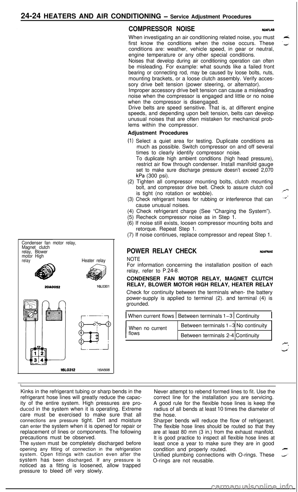
Condenser fan motor relay,
Magnet clutch
relay, Blower
motor High
relayHeater relayML0312
16W908
POWER RELAY CHECKNUFNAE
NOTEFor information concerning the installation position of each
relay, refer to
P.24-8.CONDENSER FAN MOTOR RELAY, MAGNET CLUTCH
RELAY, BLOWER MOTOR HIGH RELAY, HEATER RELAY
Check for continuity between the terminals when- the battery
power-supply is applied to terminal (2). and terminal (4) is
grounded.
1 When current flows 1 Between terminals l-3 1 Continuity1
I
When no currentBetween terminals l-3 No continuity
flowsBetween terminals 2-4 Continuity
IKinks in the refrigerant tubing or sharp bends in the
Never attempt to rebend formed lines to fit. Use the
refrigerant hose lines will greatly reduce the
capac-correct line for the installation you are servicing.
ity of the entire system. High pressures are
pro-A good rule for the flexible hose lines is keep the
duced in the system when it is operating. Extreme
radius of all bends at least 10 times the diameter of
care must be exercised to make sure that all
the hose.
connections are pressure tight. Dirt and moisture
Sharper bends will reduce the flow of refrigerant.
can enter the system when it is opened for repair or
The flexible hose lines should be routed so that theyreplacement of lines or components. The following
are at least 80 mm (3 in.) from the exhaust manifold.precautions must be observed.
It is good practice to inspect all flexible hose lines atThe system must be completely discharged before
least once a year to make sure they are in good
opening any fitting of connection in the refrigeration
condition and properly routed.
Fsystem. Open fittings with caution even after the
Unified plumbing connections with O-rings. These
4’system has been discharged. If any pressure is
noticed as a fitting is loosened, allow trappedO-rings are not reusable.
pressure to bleed off very slowly.
Page 1169 of 1216
HEATERS AND AIR CONDITIONING - Service Adjustment Procedures 24-25
16A1077
20AO499
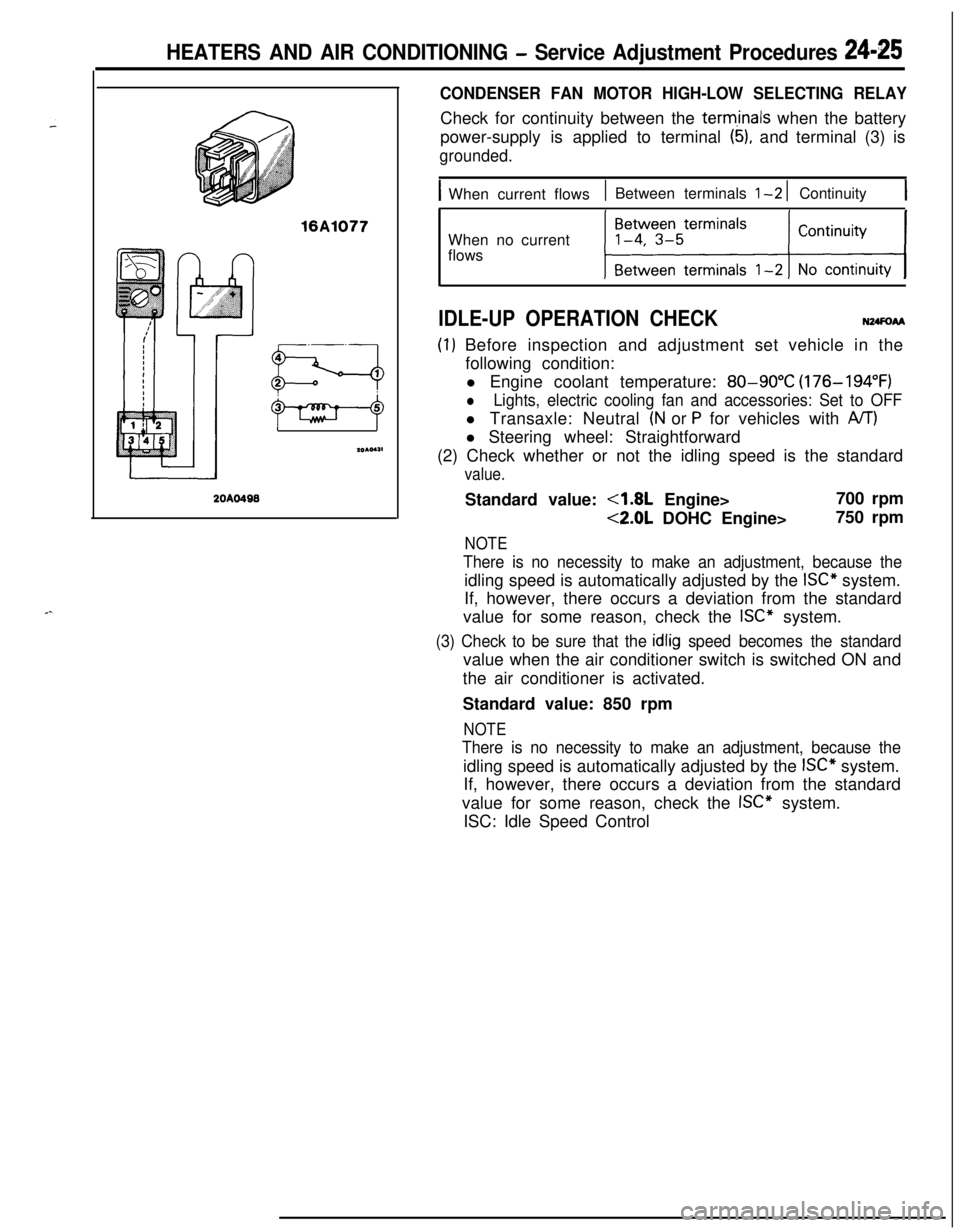
CONDENSER FAN MOTOR HIGH-LOW SELECTING RELAYCheck for continuity between the
term,inals when the battery
power-supply is applied to terminal
(5), and terminal (3) is
grounded.
IWhen current flows1 Between terminals l-2 1 Continuity1When no current
flows
IDLE-UP OPERATION CHECKN24FoAA
(I) Before inspection and adjustment set vehicle in the
following condition:
l Engine coolant temperature:
80-90°C (176-194°F)
lLights, electric cooling fan and accessories: Set to OFFl Transaxle: Neutral
(N or P for vehicles with A/T)l Steering wheel: Straightforward
(2) Check whether or not the idling speed is the standard
value.Standard value:
4.8L Engine>700 rpm
<2.0L DOHC Engine>750 rpm
NOTE
There is no necessity to make an adjustment, because theidling speed is automatically adjusted by the
ISC” system.
If, however, there occurs a deviation from the standard
value for some reason, check the
ISC” system.
(3) Check to be sure that the idlig speed becomes the standardvalue when the air conditioner switch is switched ON and
the air conditioner is activated.
Standard value: 850 rpm
NOTE
There is no necessity to make an adjustment, because theidling speed is automatically adjusted by the
ISC” system.
If, however, there occurs a deviation from the standard
value for some reason, check the
ISC” system.
ISC: Idle Speed Control
Page 1181 of 1216
HEATERS AND AIR CONDITIONING - ComDressor24-37
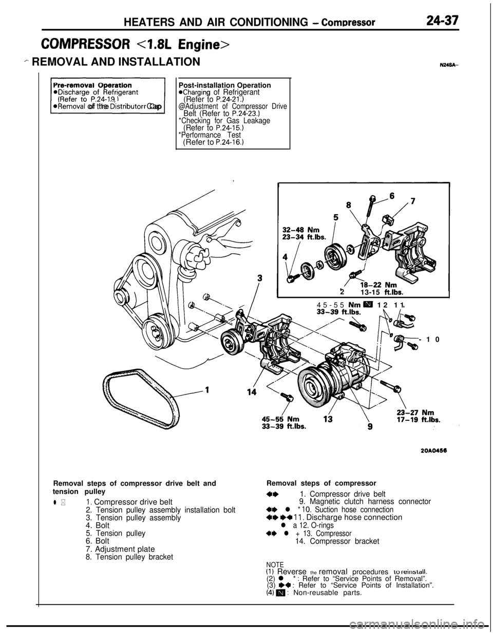
COMPRESSOR <7.8L Engine>
em REMOVAL AND INSTALLATION
F)
*Removal of the distributor CapPost-installation Operation
@Charging of Refrigerant
(Refer to P.24-21.)@Adjustment of Compressor DriveBelt (Refer to P.24-23.)*Checking for Gas Leakage(Refer to P.24-15.)*Performance Test(Refer to P.24-16.)Removal steps of compressor drive belt and
tension pulley
l *1, Compressor drive belt2. Tension pulley assembly installation bolt
3. Tension pulley assembly4. Bolt
5. Tension pulley6. Bolt
7. Adjustment plate
8. Tension pulley bracket2
13-15
ft.lbs.45-55 Nm
H 12 11
-10
2OAO456Removal steps of compressor
4*1. Compressor drive belt
9. Magnetic clutch harness connector
+e l * 10. Suction hose connection+e I)+ 11. Discharge hose connectionl a 12. O-rings
+* l + 13. Compressor14. Compressor bracket
NOTE(1) Reverse the removal procedures to reinstall.(2) l * : Refer to “Service Points of Removal”.
(3) W : Refer to “Service Points of Installation”.(4) m : Non-reusable parts.
Page 1189 of 1216
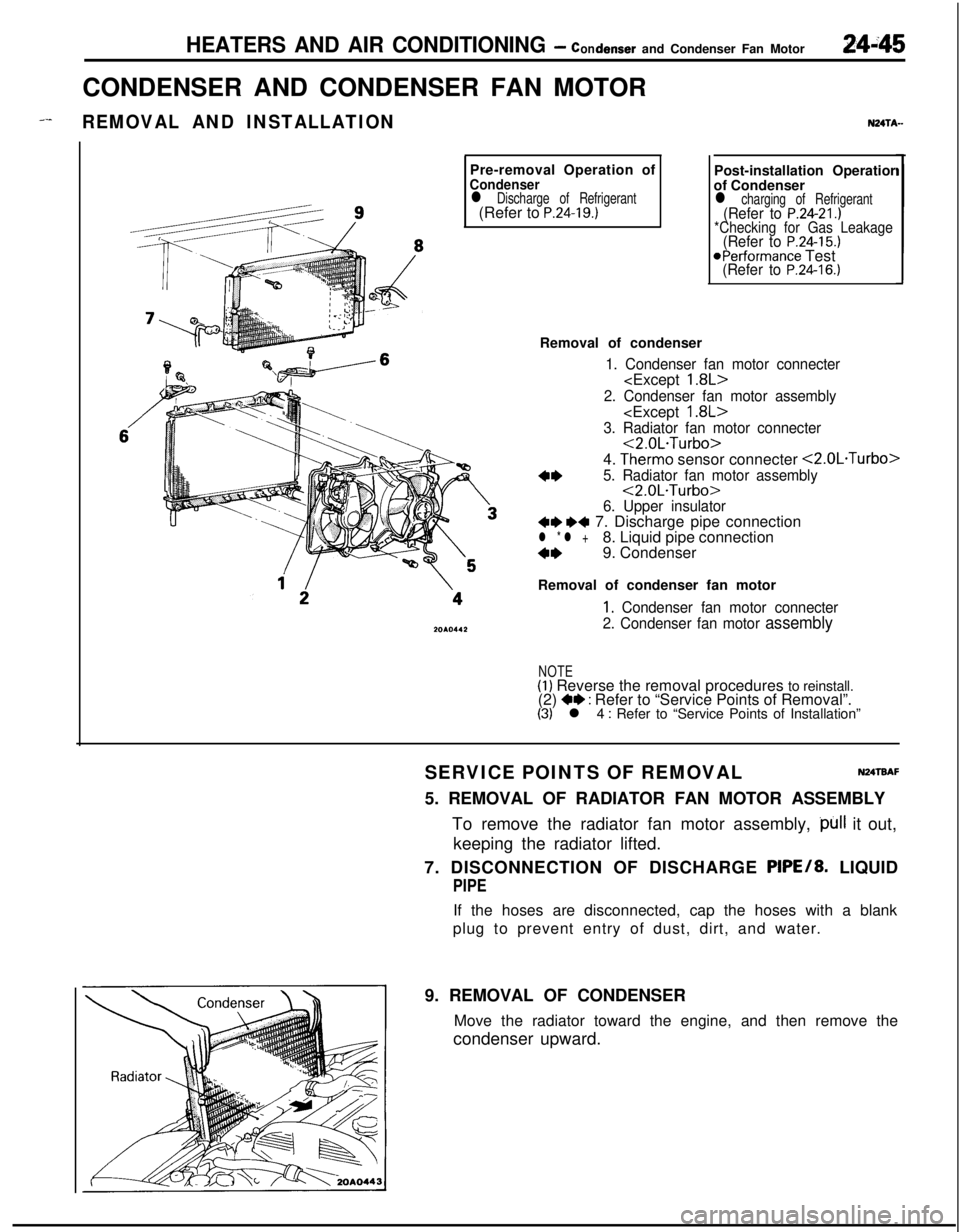
HEATERS AND AIR CONDITIONING - condenser and Condenser Fan Motor24i45CONDENSER AND CONDENSER FAN MOTOR
_--REMOVAL AND INSTALLATIONPre-removal Operation of
Condenserl Discharge of Refrigerant(Refer to P.24-19.)
NZITA-Post-installation Operatior
of Condenser
l charging of Refrigerant(Refer to P.24-21.)*Checking for Gas Leakage(Refer to P.24-15.)@Performance Test(Refer to P.24-16.)Removal of condenser
1. Condenser fan motor connecter
2. Condenser fan motor assembly
3. Radiator fan motor connecter<2.0L.Turbo>
4.
Therm0 sensor connecter <2.0L.Turbo>
4*5. Radiator fan motor assembly<2.0L.Turbo>
6. Upper insulator+e ~~ 7. Discharge pipe connectionl * l +8. Liquid pipe connection
4*9. Condenser
Removal of condenser fan motor
1, Condenser fan motor connecter
2. Condenser fan motor
assembly
NOTE(1) Reverse the removal procedures to reinstall.
(2) +e : Refer to “Service Points of Removal”.(3) l 4 : Refer to “Service Points of Installation”
SERVICE POINTS OF REMOVAL
N24TBAF5. REMOVAL OF RADIATOR FAN MOTOR ASSEMBLY
To remove the radiator fan motor assembly,
)~ll it out,
keeping the radiator lifted.
7. DISCONNECTION OF DISCHARGE PIPE/8. LIQUID
PIPEIf the hoses are disconnected, cap the hoses with a blank
plug to prevent entry of dust, dirt, and water.
9. REMOVAL OF CONDENSER
Move the radiator toward the engine, and then remove the
condenser upward.
Page 1195 of 1216
HEATERS AND AIR CONDITIONING- Engine Coolant Temperature Switch24-51
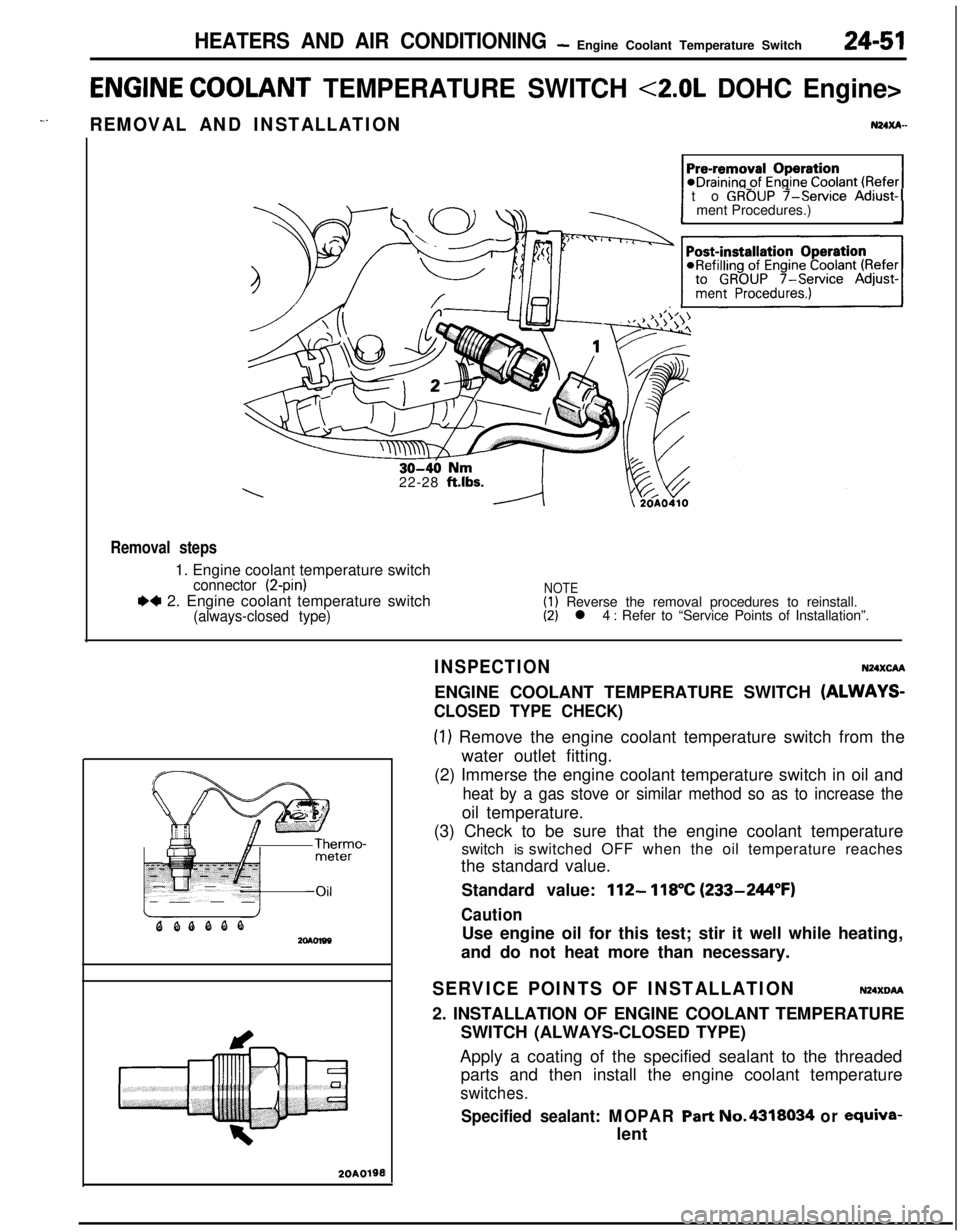
ENGINE COOLANT TEMPERATURE SWITCH <2.0L DOHC Engine>
-.REMOVAL AND INSTALLATIONN24xA-
1 to GROUP f-service Adjust-1ment Procedures.)
22-28
ft.lbs.
Removal steps1. Engine coolant temperature switch
connector (2-pin)
.4 2. Engine coolant temperature switch(always-closed type)
NOTE(1) Reverse the removal procedures to reinstall.(2) l 4 : Refer to “Service Points of Installation”.
20A0190I
INSPECTIONN24XcAAENGINE COOLANT TEMPERATURE SWITCH
(ALWAYS-
CLOSED TYPE CHECK)
(1) Remove the engine coolant temperature switch from the
water outlet fitting.
(2) Immerse the engine coolant temperature switch in oil and
heat by a gas stove or similar method so as to increase theoil temperature.
(3) Check to be sure that the engine coolant temperature
switch is switched OFF when the oil temperature reaches
the standard value.
Standard value:
112- 118°C (233-244°F)
CautionUse engine oil for this test; stir it well while heating,
and do not heat more than necessary.
SERVICE POINTS OF INSTALLATIONN24XDM2. INSTALLATION OF ENGINE COOLANT TEMPERATURE
SWITCH (ALWAYS-CLOSED TYPE)
Apply a coating of the specified sealant to the threaded
parts and then install the engine coolant temperature
switches.
Specified sealant: MOPAR Part No.4318034 or ewiva-lent
Page 1199 of 1216

-.
EMISSION CONTROL SYSTEMS - Troubleshooting
TROUBLESHOOTING
., ,_
SymptomProbable causeRemedy
Engine will not start or hard toVacuum hose disconnected or damaged
Repair or replacestart
The EGR valve is not closedMalfunction of the purge control solenoid
valve
Rough idle or engine stalls
The EGR valve is not closed.
Repair or replace
Vacuum hose disconnected or damagedMalfunction of the positive crankcase
ventilation valve
ReplaceMalfunction of the purge control system
Check the system; if there is a problem,
check its component parts
Engine hesitates or poor accel-Malfunction of the exhaust gas
recircula-Check the system; if there is a problem,
erationtion systemcheck its component parts
Excessive oil consumptionPositive crankcase ventilation line cloggedCheck positive crankcase ventilation sys-tem
Poor fuel mileageMalfunction of the exhaust gas recircula-Check the system; if there is a problem,tion systemcheck its component parts
Page 1203 of 1216
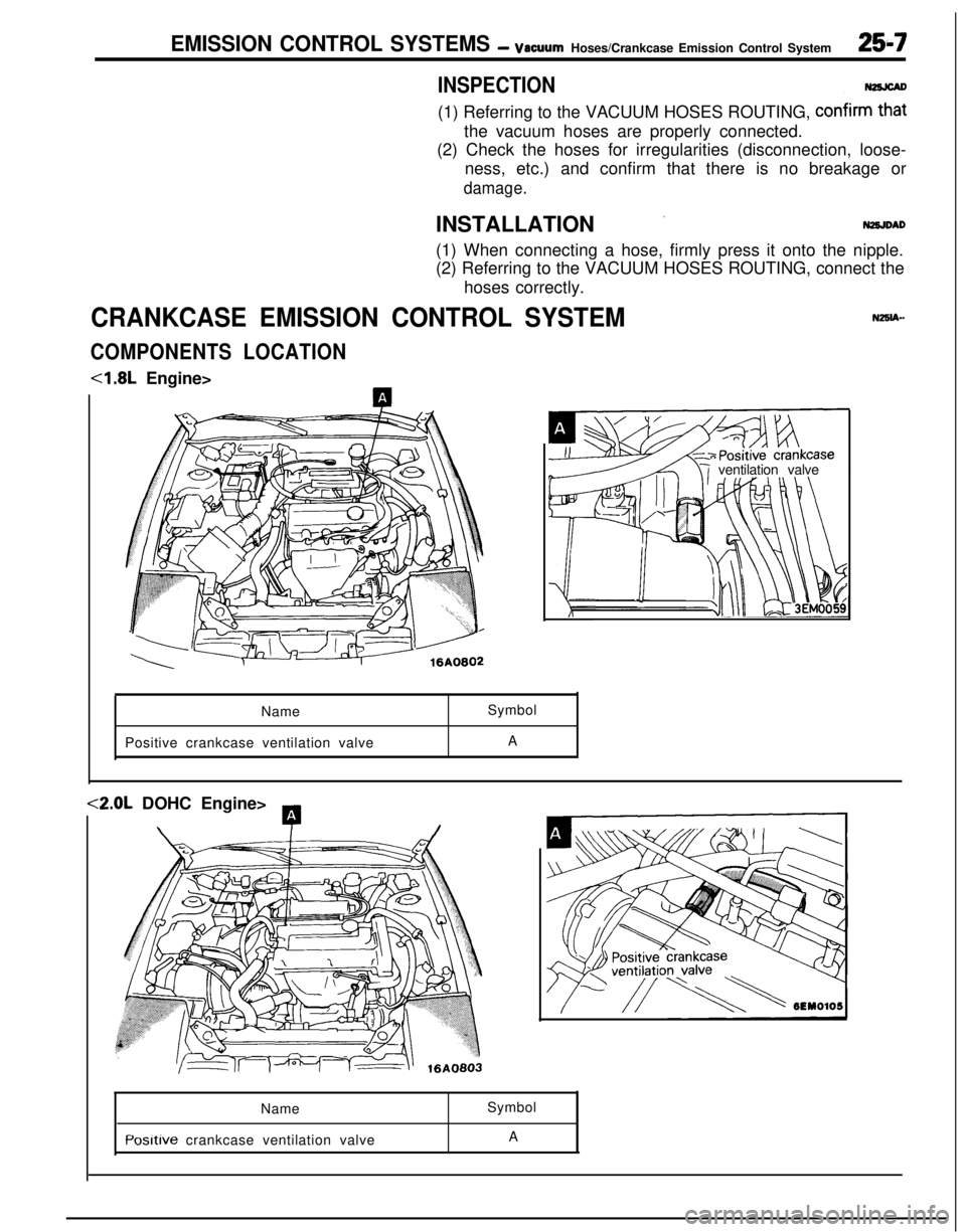
EMISSION CONTROL SYSTEMS - vacuumHoses/Crankcase Emission Control System25-7
INSPECTION(1) Referring to the VACUUM HOSES ROUTING,
confirm2the vacuum hoses are properly connected.
(2) Check the hoses for irregularities (disconnection, loose-
ness, etc.) and confirm that there is no breakage or
damage.INSTALLATION
’N2SJDAD(1) When connecting a hose, firmly press it onto the nipple.
(2) Referring to the VACUUM HOSES ROUTING, connect the
hoses correctly.
CRANKCASE EMISSION CONTROL SYSTEM
COMPONENTS LOCATION<1.8L Engine>
ventilation valve
NameSymbol
Positive crankcase ventilation valveA<2.0L DOHC Engine>
A
\T/Name
Posltive crankcase ventilation valveSymbol
A