engine MITSUBISHI ECLIPSE 1991 Service Manual
[x] Cancel search | Manufacturer: MITSUBISHI, Model Year: 1991, Model line: ECLIPSE, Model: MITSUBISHI ECLIPSE 1991Pages: 1216, PDF Size: 67.42 MB
Page 378 of 1216
9-94
ENGINE <2.0L DOHC Engine> - Cvlinder Head Gasket
olAoo41Delivery pipe
/High pressure
hoseb-ringD3AOQ79
04AOD98
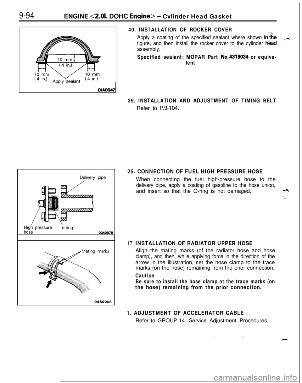
40. INSTALLATION OF ROCKER COVER
Apply a coating of the specified sealant where shown in$e
figure, and then install the rocker cover to the cylinder Head
assembly.
Specified sealant: MOPAR Part No.4318034 or equiva-
lent
39. INSTALLATION AND ADJUSTMENT OF TIMING BELTRefer to
P.9-104.
25. CONNECTION OF FUEL HIGH PRESSURE HOSEWhen connecting the fuel high-pressure hose to the
delivery pipe, apply a coating of gasoline to the hose union,and insert so that the O-ring is not damaged.
17. INSTALLATION OF RADIATOR UPPER HOSEAlign the mating marks (of the radiator hose and hose
clamp), and then, while applying force in the direction of thearrow in the illustration, set the hose clamp to the trace
marks (on the hose) remaining from the prior connection.
Caution
Be sure to install the hose clamp at the trace marks (on
the hose) remaining from the prior connection.
1. ADJUSTMENT OF ACCELERATOR CABLERefer to GROUP
14-Service Adjustment Procedures.
Page 379 of 1216
ENGINE <2.0L DOHC Engine> - Timing Belt
TIMING BELT
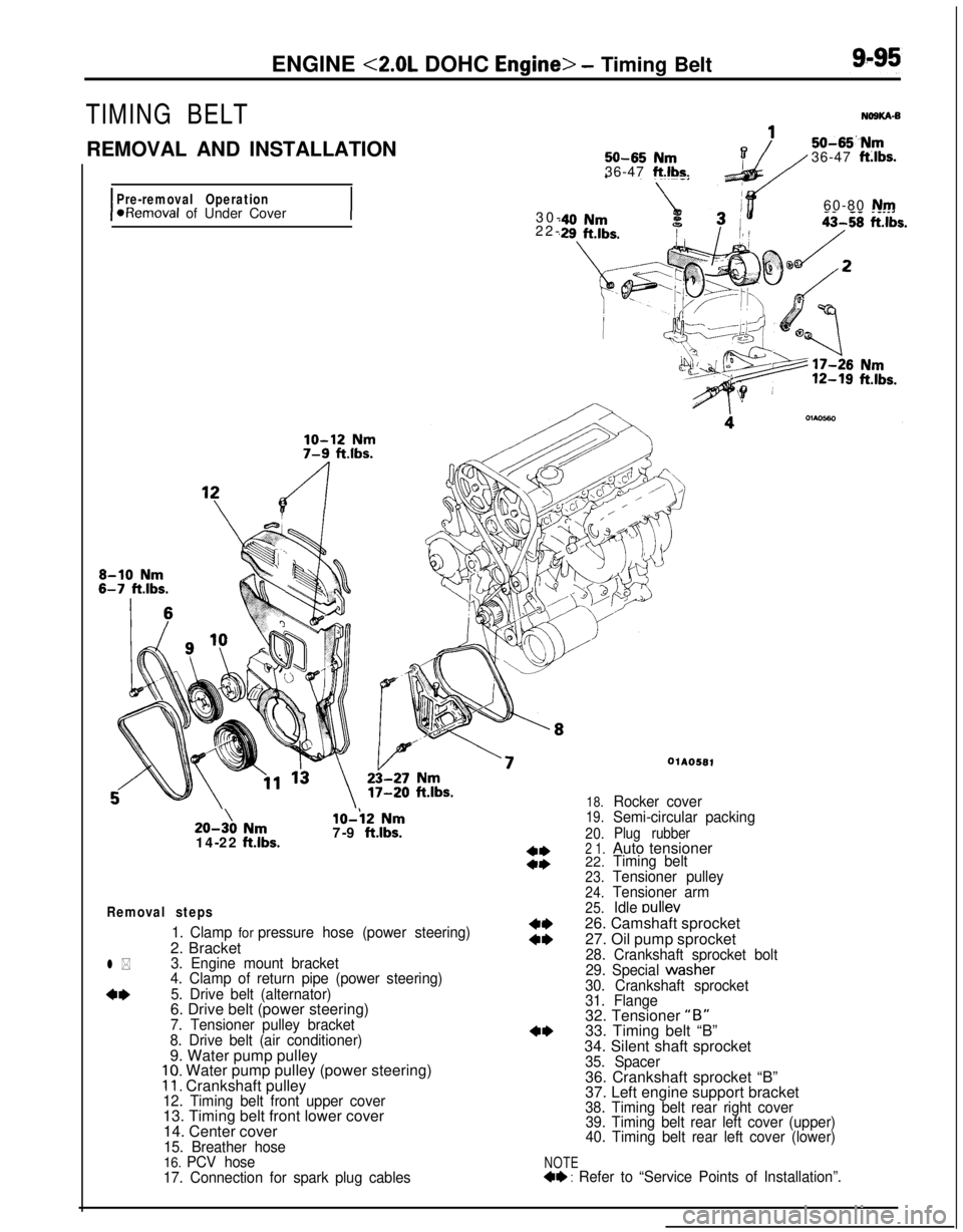
REMOVAL AND INSTALLATION
I
Pre-removal Operation*Removal of Under Cover
I
50-65 Nm36-47 ft.lbs.
50-65“Nm36-47 ft:lbs.30-60-80
Nm22-20-3\0
Nm14-22 ftlbs.
lo-i2 Nm7-9 ftlbs.
Removal steps
1. Clamp for pressure hose (power steering)2. Bracket
3. Engine mount bracket
4. Clamp of return pipe (power steering)
5. Drive belt (alternator)6. Drive belt (power steering)
7. Tensioner pulley bracket
8. Drive belt (air conditioner)9. Water pump pulley
10. Water pump pulley (power steering)11. Crankshaft pulley12. Timing belt front upper cover13. Timing belt front lower cover
14. Center cover
15. Breather hose16. PCV hose
17. Connection for spark plug cables
l *
4*
NOTE4+ : Refer to “Service Points of Installation”.
WA0581
18.Rocker cover19.Semi-circular packing
20.Plug rubber2 1.Auto tensioner
22.Timing belt
23.Tensioner pulley
24.Tensioner arm
25.Idle oullev26. Camshaft sprocket
27. Oil pump sprocket
28. Crankshaft sprocket bolt
29. Special wastier
30. Crankshaft sprocket
31. Flange32. Tensioner
“B”33. Timing belt “B”
34. Silent shaft sprocket
35. Spacer36. Crankshaft sprocket “B”
37. Left engine support bracket
38. Timing belt rear right cover
39. Timing belt rear left cover (upper)
40. Timing belt rear left cover (lower)
Page 380 of 1216
9-96ENGINE <2.0L DOHC Engine> - Timing Belt
116
/18
Iv- IL 1’11117-9 ftlbs.
\43-49
Nm-_---. . .
30-42 Nm$0
22-30 ftlbs.
\
j2 \ 36
33
15-22 Nm
11-16 ftlbs.
I20-27 Nm\h \
14-20 f&.lbs.110-130 Nm cI,60-94 f
\z/OIAOS83-ama .I~..su--Du Nrnt Ibs .,iJ 36-43 ft.lbs.. .
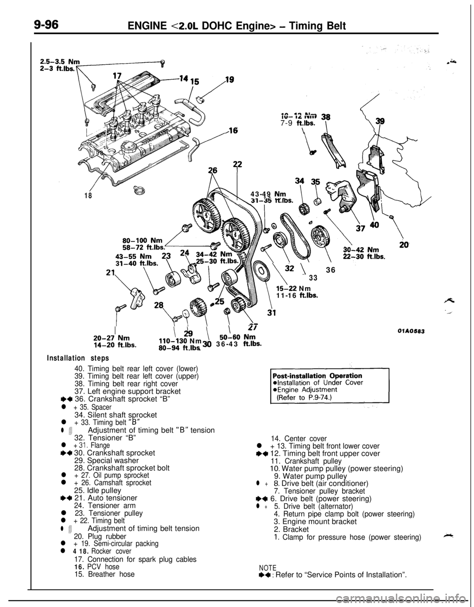
Installation steps
40. Timing belt rear left cover (lower)
39. Timing belt rear left cover (upper)
38. Timing belt rear right cover37. Left engine support bracket
I)+ 36. Crankshaft sprocket “B”
l + 35. Spacer34. Silent shaft sprocket
l + 33. Timing belt “B”
l 4Adjustment of timing belt “B” tension
32. Tensioner “B”
l + 31. Flange++ 30. Crankshaft sprocket
29. Special washer
28. Crankshaft sprocket bolt
l + 27. Oil pump sprocketl + 26. Camshaft sprocket25. Idle pulley
e+ 21. Auto tensioner24. Tensioner arml 23. Tensioner pulleyl + 22. Timing belt
l 4Adjustment of timing belt tension20. Plug rubberl + 19. Semi-circular packingl 4 18. Rocker cover
17. Connection for spark plug cables16. PCV hose15. Breather hose14. Center cover
l + 13. Timing belt front lower covere+ 12. Timing belt front upper cover11. Crankshaft pulley10. Water pump pulley (power steering)
9. Water pump pulley
l +8. Drive belt (air conditioner)7. Tensioner pulley bracketI)+ 6. Drive belt (power steering)l +5. Drive belt (alternator)
4. Return pipe clamp bolt (power steering)3. Engine mount bracket
2. Bracket
1. Clamp for pressure hose (power steering)
NOTE+4 : Refer to “Service Points of Installation”.
Page 381 of 1216
--ENGINE
<2.0L DOHC Engine> - Timing Belt9-97
ExhaustIntake cam-
CrankshaftsproketsprockekOlhw51
1r
SERVICE POINTS OF REMOVAL-a3. REMOVAL OF ENGINE MOUNT BRACKET
(1) With a wooden block placed against the oil pan part of
the engine, jack up the vehicle.
CautionJack up gently, so as not to apply a load to the
various parts.
(2) Remove the engine mount bracket,
5. REMOVAL OF DRIVE BELT (ALTERNATOR)
Before removing the drive belt, loosen the water pump
pulley mounting bolts.
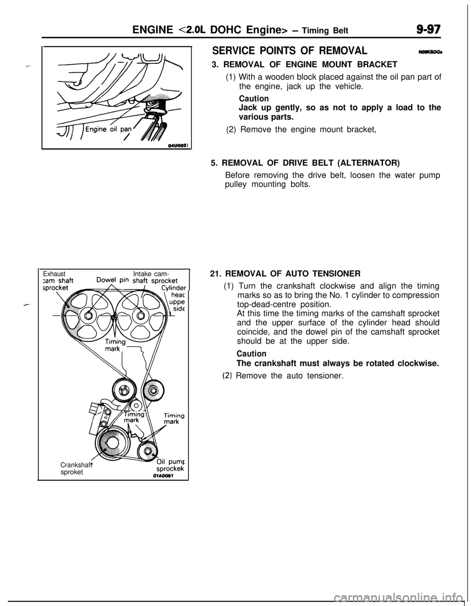
21. REMOVAL OF AUTO TENSIONER
(1) Turn the crankshaft clockwise and align the timing
marks so as to bring the No. 1 cylinder to compression
top-dead-centre position.
At this time the timing marks of the camshaft sprocket
and the upper surface of the cylinder head should
coincide, and the dowel pin of the camshaft sprocket
should be at the upper side.
CautionThe crankshaft must always be rotated clockwise.
(2‘) Remove the auto tensioner.
Page 382 of 1216
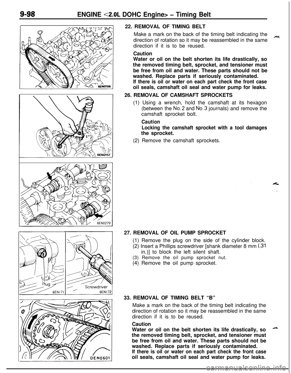
9-98ENGINE <2.0L DOHC Engine> - Timing Belt22. REMOVAL OF TIMING BELT
Make a mark on the back of the timing belt indicating the
direction of rotation so it may be reassembled in the same
~direction if it is to be reused.
Caution
Water or oil on the belt shorten its life drastically, so
the removed timing belt, sprocket, and tensioner must
be free from oil and water. These parts should not be
washed. Replace parts if seriously contaminated.
If there is oil or water on each part check the front caseoil seals, camshaft oil seal and water pump for leaks.
26. REMOVAL OF CAMSHAFT SPROCKETS
(1) Using a wrench, hold the camshaft at its hexagon
(between the No.2 and No.3 journals) and remove the
camshaft sprocket bolt.
Caution
Locking the camshaft sprocket with a tool damagesthe sprocket.
(2) Remove the camshaft sprockets.
127. REMOVAL OF OIL PUMP SPROCKET
(1) Remove the plug on the side of the cylinder block.
(2) Insert a Phillips screwdriver [shank diameter 8 mm
(.31in.)] to block the left silent shaft.
(3) Remove the oil pump sprocket nut.
(4) Remove the oil pump sprocket.
33. REMOVAL OF TIMING BELT “B”
Make a mark on the back of the timing belt indicating the
direction of rotation so it may be reassembled in the same
direction if it is to be reused.
Caution
Water or oil on the belt shorten its life drastically, so
++the removed timing belt, sprocket, and tensioner must
be free from oil and water. These parts should not be
washed. Replace parts if seriously contaminated.
If there is oil or water on each part check the front caseoil seals, camshaft oil seal and water pump for leaks.
Page 383 of 1216
ENGINE <2.0L DOHC Engine> - Timing Belt9-99
-
\
Q+i!il
008ooo
rackCrack
7EN207
SeparationRounded belt side
Abnormal wear
(fluffy canvas fiber)
7EN208
Rubber
exposedTooth missing and
canvas fiber
exoosed
7EN2096EN0159
-
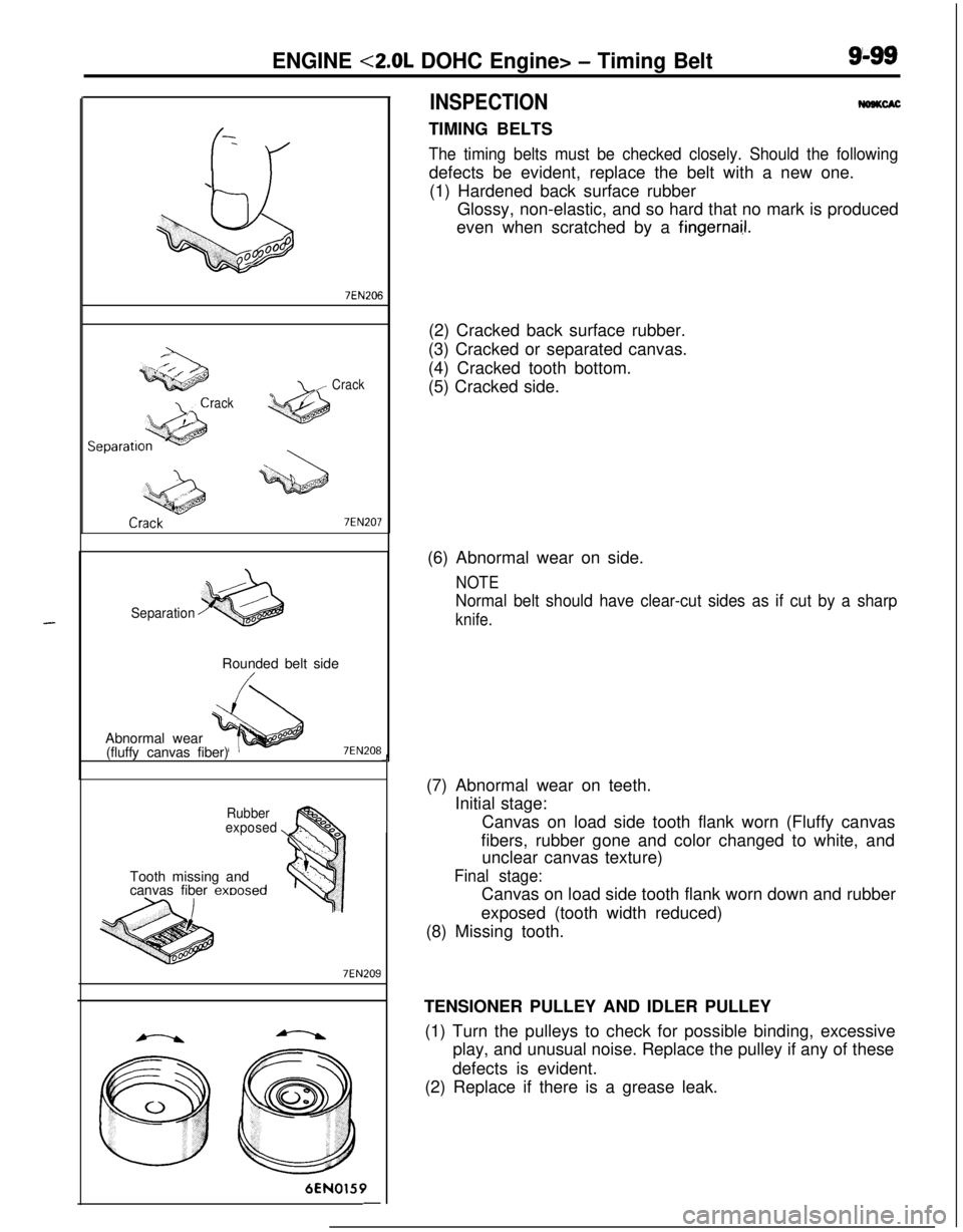
INSPECTIONWSKCACTIMING BELTS
The timing belts must be checked closely. Should the followingdefects be evident, replace the belt with a new one.
(1) Hardened back surface rubber
Glossy, non-elastic, and so hard that no mark is produced
even when scratched by a
fingernai.1.(2) Cracked back surface rubber.
(3) Cracked or separated canvas.
(4) Cracked tooth bottom.
(5) Cracked side.J(6) Abnormal wear on side.
NOTE
Normal belt should have clear-cut sides as if cut by a sharp
knife.(7) Abnormal wear on teeth.
Initial stage:
Canvas on load side tooth flank worn (Fluffy canvas
fibers, rubber gone and color changed to white, and
unclear canvas texture)
Final stage:Canvas on load side tooth flank worn down and rubber
exposed (tooth width reduced)
(8) Missing tooth.
TENSIONER PULLEY AND IDLER PULLEY
(1) Turn the pulleys to check for possible binding, excessive
play, and unusual noise. Replace the pulley if any of these
defects is evident.
(2) Replace if there is a grease leak.
Page 384 of 1216
9-100ENGINE <2.0L DOHC Engine> - Timing Belt
6EN028012 mm
(.47 in.)
6EN0161
Plug6EN0281
Crankshaft
sprocket“BJ
Crankshaft
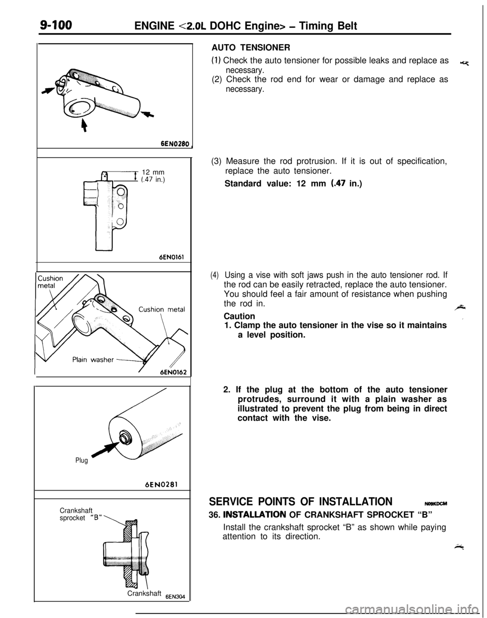
6EN304AUTO TENSIONER
(1) Check the auto tensioner for possible leaks and replace as*
necessary.(2) Check the rod end for wear or damage and replace as
necessary.(3) Measure the rod protrusion. If it is out of specification,
replace the auto tensioner.
Standard value: 12 mm
(.47 in.)
(4)Using a vise with soft jaws push in the auto tensioner rod. Ifthe rod can be easily retracted, replace the auto tensioner.
You should feel a fair amount of resistance when pushing
the rod in.
,J-Caution
’1. Clamp the auto tensioner in the vise so it maintains
a level position.
2. If the plug at the bottom of the auto tensioner
protrudes, surround it with a plain washer as
illustrated to prevent the plug from being in direct
contact with the vise.
SERVICE POINTS OF INSTALLATIONmsmm36. INSTALLATlON OF CRANKSHAFT SPROCKET “B”
Install the crankshaft sprocket “B” as shown while paying
attention to its direction.
i;4
Page 385 of 1216
ENGINE <2.0L DOHC Engine> - Timinn Belt
SpacerChahfered
6s
il seal
6EN009Silent shaft
nsprocketI
Timing
markCrankshaft
) ~sprocket “6”Center of
tensioner
pulley
Center of
installation bolt
installation bolt
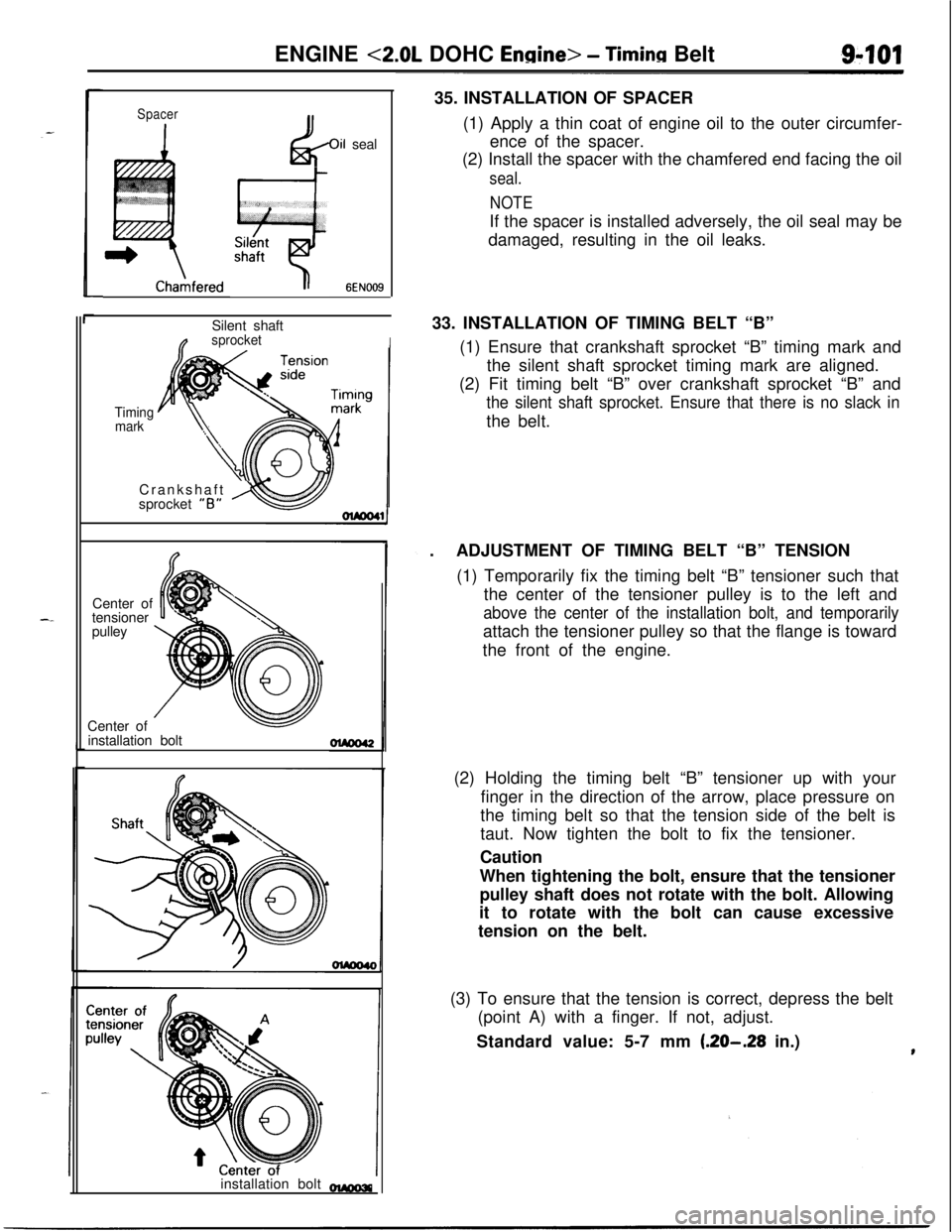
-35. INSTALLATION OF SPACER
(1) Apply a thin coat of engine oil to the outer circumfer-
ence of the spacer.
(2) Install the spacer with the chamfered end facing the oil
seal.
NOTEIf the spacer is installed adversely, the oil seal may be
damaged, resulting in the oil leaks.
33. INSTALLATION OF TIMING BELT “B”
(1) Ensure that crankshaft sprocket “B” timing mark and
the silent shaft sprocket timing mark are aligned.
(2) Fit timing belt “B” over crankshaft sprocket “B” and
the silent shaft sprocket. Ensure that there is no slack inthe belt.
.ADJUSTMENT OF TIMING BELT “B” TENSION
(1) Temporarily fix the timing belt “B” tensioner such that
the center of the tensioner pulley is to the left and
above the center of the installation bolt, and temporarilyattach the tensioner pulley so that the flange is toward
the front of the engine.
(2) Holding the timing belt “B” tensioner up with your
finger in the direction of the arrow, place pressure on
the timing belt so that the tension side of the belt is
taut. Now tighten the bolt to fix the tensioner.
Caution
When tightening the bolt, ensure that the tensioner
pulley shaft does not rotate with the bolt. Allowing
it to rotate with the bolt can cause excessive
tension on the belt.
(3) To ensure that the tension is correct, depress the belt
(point A) with a finger. If not, adjust.
Standard value: 5-7 mm
(.20-.28 in.)
Page 386 of 1216
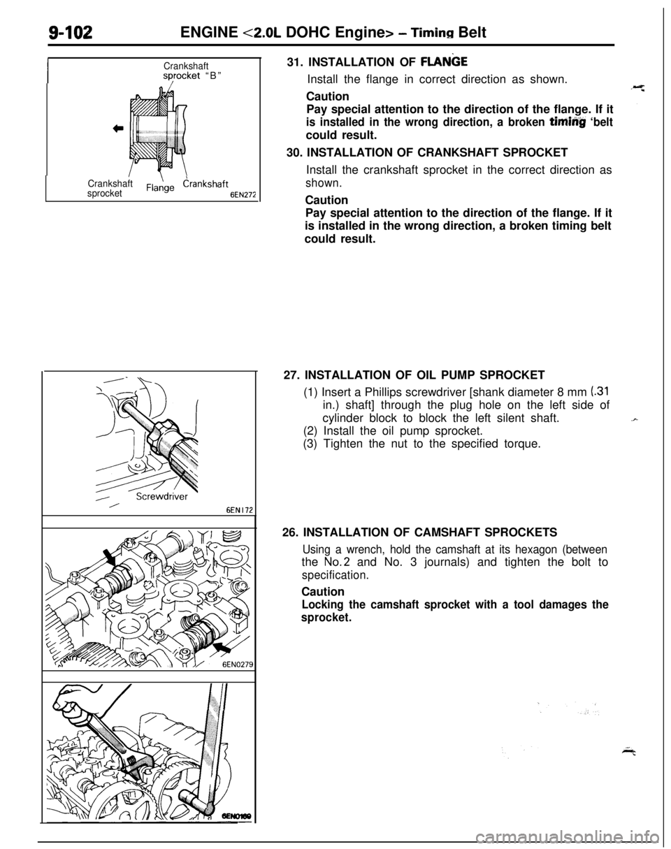
S-102ENGINE <2.0L DOHC Engine> - Timing Belt
Crankshaftsyocket “B”
Crankshaft
sprocketdrankshaft 6fN272
6EN I1231. INSTALLATION OF
FLANGEInstall the flange in correct direction as shown.
Caution
Pay special attention to the direction of the flange. If it
is installed in the wrong direction, a broken timiiig ‘beltcould result.
30. INSTALLATION OF CRANKSHAFT SPROCKET
Install the crankshaft sprocket in the correct direction as
shown.Caution
Pay special attention to the direction of the flange. If it
is installed in the wrong direction, a broken timing belt
could result.
27. INSTALLATION OF OIL PUMP SPROCKET
(1) Insert a Phillips screwdriver [shank diameter 8 mm
(.31in.) shaft] through the plug hole on the left side of
cylinder block to block the left silent shaft.
(2) Install the oil pump sprocket.
(3) Tighten the nut to the specified torque.
26. INSTALLATION OF CAMSHAFT SPROCKETS
Using a wrench, hold the camshaft at its hexagon (betweenthe
No.2 and No. 3 journals) and tighten the bolt to
specification.Caution
Locking the camshaft sprocket with a tool damages the
sprocket.
Page 387 of 1216

ENGINE <2.0L DOHC Engine> - Timing Belts-103
--
Plug
6EN0281Center bolt
I
6EN028321. INSTALLATION OF AUTO TENSIONER
(1) If the auto tensioner rod is in its fully extended position,reset it as follows.
@ Keep the a t tu oensioner level and, in that position,
clamp it in the vise with soft jaws.
If the plug at the bottom of the auto tensioner
protrudes, surround it with a plain washer as
illustrated to prevent the plug from being in direct
contact with the vise.
@I Push in the rod little by little with the vise until the
set hole
@ in the rod is aligned with that @I in the
cylinder.
@ Insert a wire [1.4 mm (055 in.) in diameter] into the
set holes.
@I Unclamp the auto tensioner from the vise.
(2) Install the auto tensioner.
Caution
Leave the wire installed in the auto tensioner.
23. INSTALLATION OF TENSIONER PULLEY
(1) Install the tensioner pulley onto the tensioner arm.
(2) Locate the pinhole in the tensioner pulley shaft to the
left of the center bolt. Then, tighten the center bolt
finger-tight.Caution
Leave the wire installed in the auto tensioner.