engine MITSUBISHI ECLIPSE 1991 Service Manual
[x] Cancel search | Manufacturer: MITSUBISHI, Model Year: 1991, Model line: ECLIPSE, Model: MITSUBISHI ECLIPSE 1991Pages: 1216, PDF Size: 67.42 MB
Page 338 of 1216
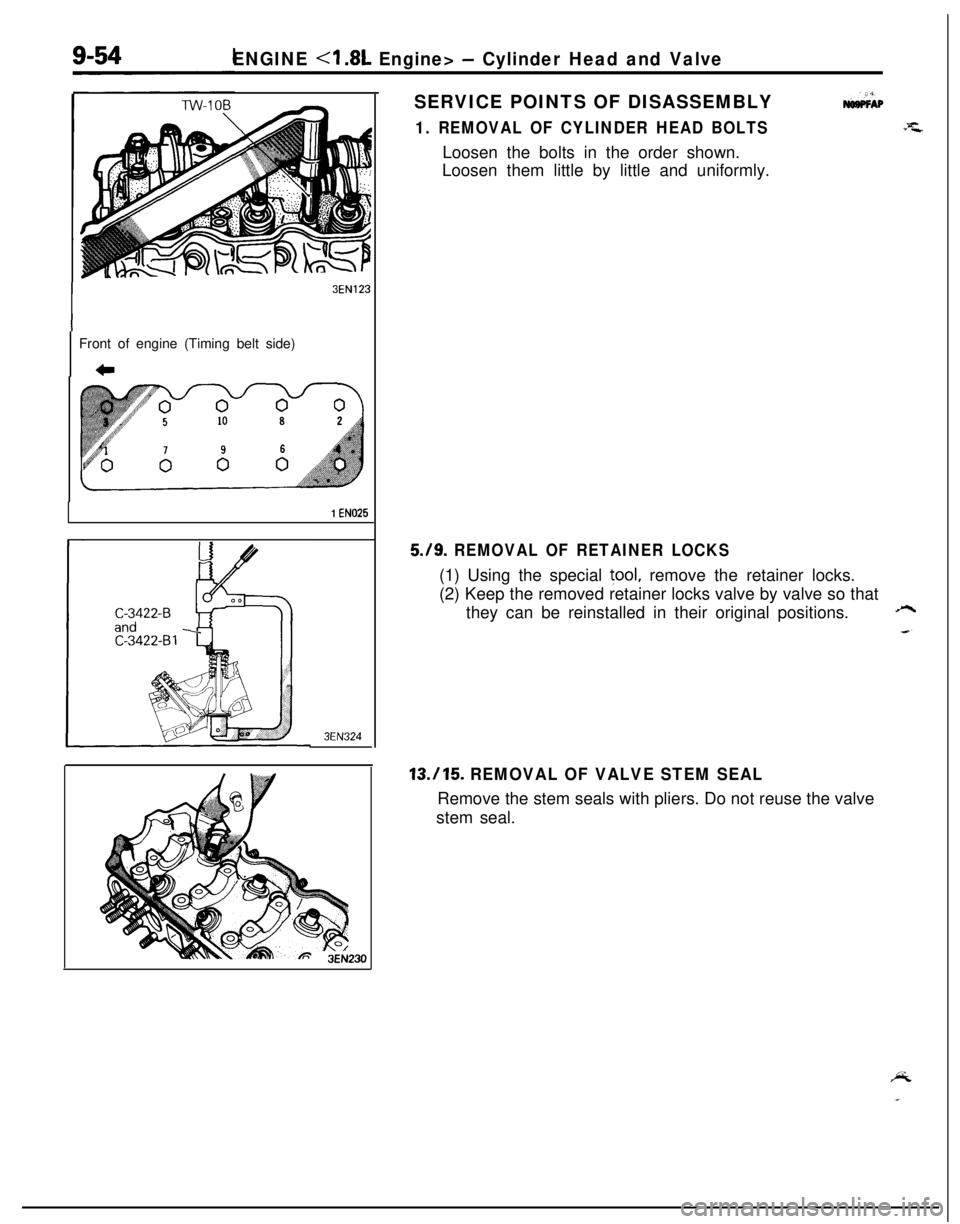
ENGINE - Cylinder Head and ValveSERVICE POINTS OF DISASSEMBLY
1. REMOVAL OF CYLINDER HEAD BOLTS
3EN123Front of engine (Timing belt side)
c
1 EN025
3EN324Loosen the bolts in the order shown.
Loosen them little by little and uniformly.
5./9. REMOVAL OF RETAINER LOCKS(1) Using the special
tool, remove the retainer locks.
(2) Keep the removed retainer locks valve by valve so that
they can be reinstalled in their original positions.
A
13.115. REMOVAL OF VALVE STEM SEALRemove the stem seals with pliers. Do not reuse the valve
stem seal.
Page 339 of 1216
ENGINE - Cylinder Head and Valve9-55
3EN026
w -w===j=Margin , EN034
Squareness
IFree length
INSPECTION
CYLINDER HEADNosocAMl Check the cylinder head for cracks, damage and engine
coolant leakage.l
Remove the scale, sealing compound and carbon deposits
completely. After cleaning oil passages, apply compressedair to make certain that the passages are clear.
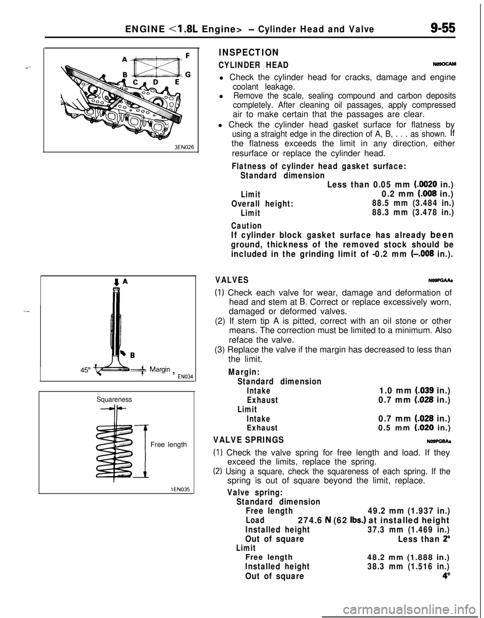
l Check the cylinder head gasket surface for flatness by
using a straight edge in the direction of A, B, . . . as shown. Ifthe flatness exceeds the limit in any direction, either
resurface or replace the cylinder head.
Flatness of cylinder head gasket surface:
Standard dimension
Limit
Overall height:
Limit
Caution
Less than 0.05 mm (0020 in.)
0.2 mm (008 in.)
88.5 mm (3.484 in.)
88.3 mm (3.478 in.)
If cylinder block gasket surface has already been
ground, thickness of the removed stock should be
included in the grinding limit of -0.2 mm
(-,008 in.).
VALVESNo9PGMa
(1) Check each valve for wear, damage and deformation of
head and stem at
B. Correct or replace excessively worn,
damaged or deformed valves.
(2) If stem tip A is pitted, correct with an oil stone or other
means. The correction must be limited to a minimum. Also
reface the valve.
(3) Replace the valve if the margin has decreased to less than
the limit.
Margin:
Standard dimension
Intake1.0 mm (.039 in.)
Exhaust0.7 mm (028 in.)
Limit
Intake0.7 mm (.028 in.)
Exhaust0.5 mm LO20 in.)
VALVE SPRINGSNOWGh
(1) Check the valve spring for free length and load. If they
exceed the limits, replace the spring.
(2) Using a square, check the squareness of each spring. If thespring is out of square beyond the limit, replace.
Valve spring:
Standard dimension
Free length
49.2 mm (1.937 in.)
Load274.6 N (62 Ibs.) at installed height
Installed height37.3 mm (1.469 in.)
Out of square
Less than 2”
Limit
Free length48.2 mm (1.888 in.)
Installed height38.3 mm (1.516 in.)
Out of square4”
Page 340 of 1216
9-56ENGINE <1.8L Engine> - Cylinder Head and ValveStem O.D.
YEN323
3EN0039
-I
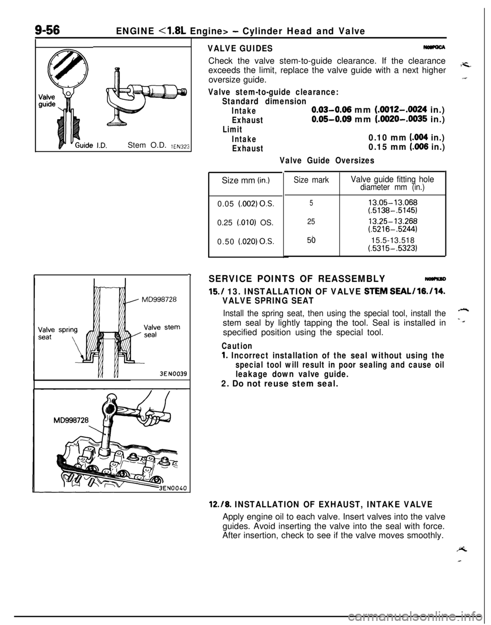
VALVE GUIDESCheck the valve stem-to-guide clearance. If the clearance
exceeds the limit, replace the valve guide with a next higher
7-c.oversize guide.“I
Valve stem-to-guide clearance:
Standard dimension
Intake0.03-0.06 mm (.0012-.0024 in.)
Exhaust0.05-0.08 mm (.0020-.0035 in.)
Limit
Intake0.10 mm (004 in.)
Exhaust0.15 mm (.006 in.)
Valve Guide OversizesSize mm
(in.)0.05
l.002) OS.0.25
LOlO) OS.
0.50
i.020) OS.
Size markValve guide fitting holediameter mm (in.)
513.05-13.068(.5138-.5145)
2513.25-13.268(.5216-.5244)
5015.5-13.518(.5315-.5323)
SERVICE POINTS OF REASSEMBLY
15./ 13. INSTALLATION OF VALVE STE,M SEAL/l6./14.
VALVE SPRING SEAT
Install the spring seat, then using the special tool, install the-stem seal by lightly tapping the tool. Seal is installed in
-dspecified position using the special tool.
Caution
1. Incorrect installation of the seal without using the
special tool will result in poor sealing and cause oil
leakage down valve guide.
2. Do not reuse stem seal.
12.18. INSTALLATION OF EXHAUST, INTAKE VALVEApply engine oil to each valve. Insert valves into the valve
guides. Avoid inserting the valve into the seal with force.
After insertion, check to see if the valve moves smoothly.PL
Page 341 of 1216
ENGINE <1.8L Engine> - Cylinder Head and Valve9-57
Enamel-
coating
sideSpring
retainerStem seal
Spring- seat
3EN324intake side
3EN315Front of engine
I,Exhaust side
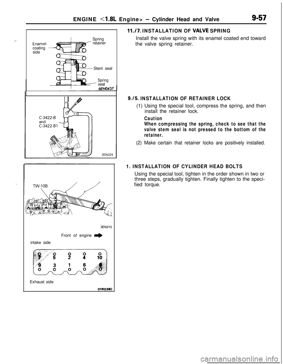
11./7. INSTALLATION OF VALVE SPRINGInstall the valve spring with its enamel coated end toward
the valve spring retainer.
9.15. INSTALLATION OF RETAINER LOCK(1) Using the special tool, compress the spring, and then
install the retainer lock.
Caution
When compressing the spring, check to see that the
valve stem seal is not pressed to the bottom of the
retainer.
(2) Make certain that retainer locks are positively installed.
1. INSTALLATION OF CYLINDER HEAD BOLTSUsing the special tool, tighten in the order shown in two or
three steps, gradually tighten. Finally tighten to the speci-
fied torque.
Page 342 of 1216
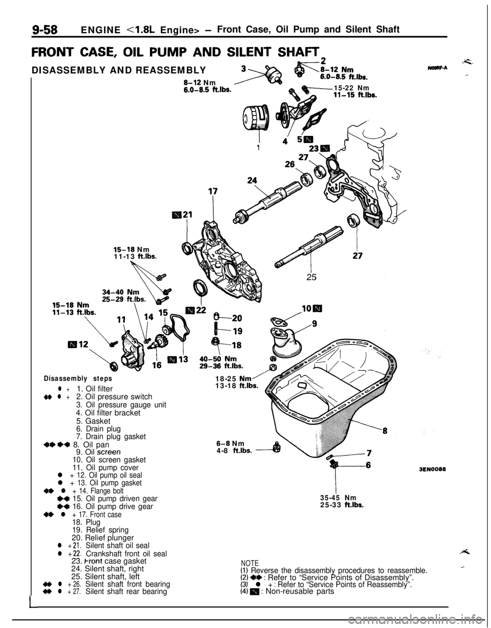
9-58ENGINE <1.8L Engine> -Front Case, Oil Pump and Silent Shaft
FRONT CASE, OIL PUMP AND SILENT SHAFTrl
L
I1
26:
25
15-18 Nm
11-13 ftlbs.DISASSEMBLY AND REASSEMBLY8-12 Nm
6.0-8.5 ft.lbs.15-22 Nm11-15 ft.lbs.
Disassembly steps
l +1. Oil filter~~ l +2. Oil pressure switch
3. Oil pressure gauge unit4. Oil filter bracket
5. Gasket
6. Drain plug
7. Drain plug gasket
+e*+ 8. Oil pan
9. Oil screen10. Oil screen gasket
11. Oil pump cover18-25
Nm/13-18 ftlbs.
8-8 Nm
4-8 ft.lbs.
l + 12. Oil pump oil seall + 13. Oil pump gasket
~~ l + 14. Flange boltI)+ 15. Oil pump driven geare+ 16. Oil pump drive gear
+e l + 17. Front case18. Plug
19. Relief spring20. Relief plunger
l + 21.Silent shaft oil seal
l + 22.Crankshaft front oil seal
35-45 Nm25-33 ftlbs.23.
Front case gasket
24. Silent shaft, right
25. Silent shaft, left
4* l + 26.Silent shaft front bearing~~ l + 27.Silent shaft rear bearing
i=G.NogRF-A.r
3EN0088
NOTE(1) Reverse the disassembly procedures to reassemble.(2) +e : Refer to “Service Points of Disassembly”.(3) l + : Refer to “Service Points of Reassembly”.(4) 0 : Non-reusable parts
Page 343 of 1216
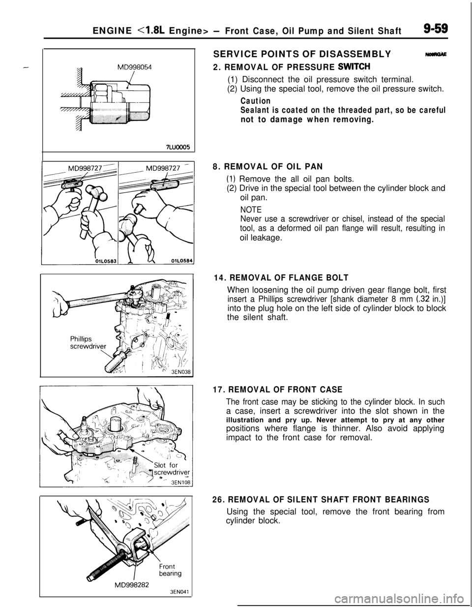
7Luooo5ENGINE
Nom&
2. REMOVAL OF PRESSURE SWITCH(1) Disconnect the oil pressure switch terminal.
(2) Using the special tool, remove the oil pressure switch.
Caution
Sealant is coated on the threaded part, so be careful
not to damage when removing.
MD9982823EN041
8. REMOVAL OF OIL PAN
(1) Remove the all oil pan bolts.
(2) Drive in the special tool between the cylinder block and
oil pan.
NOTE
Never use a screwdriver or chisel, instead of the special
tool, as a deformed oil pan flange will result, resulting inoil leakage.
14. REMOVAL OF FLANGE BOLTWhen loosening the oil pump driven gear flange bolt, first
insert a Phillips screwdriver [shank diameter 8 mm (32 in.)]into the plug hole on the left side of cylinder block to block
the silent shaft.
17. REMOVAL OF FRONT CASE
The front case may be sticking to the cylinder block. In sucha case, insert a screwdriver into the slot shown in the
illustration and pry up. Never attempt to pry at any other
positions where flange is thinner. Also avoid applying
impact to the front case for removal.
26. REMOVAL OF SILENT SHAFT FRONT BEARINGSUsing the special tool, remove the front bearing from
cylinder block.
Page 344 of 1216
S-60ENGINE <1.8L Engine> -Front Case, Oil Pump and Silent Shaft
3EN040
7LUOOO6
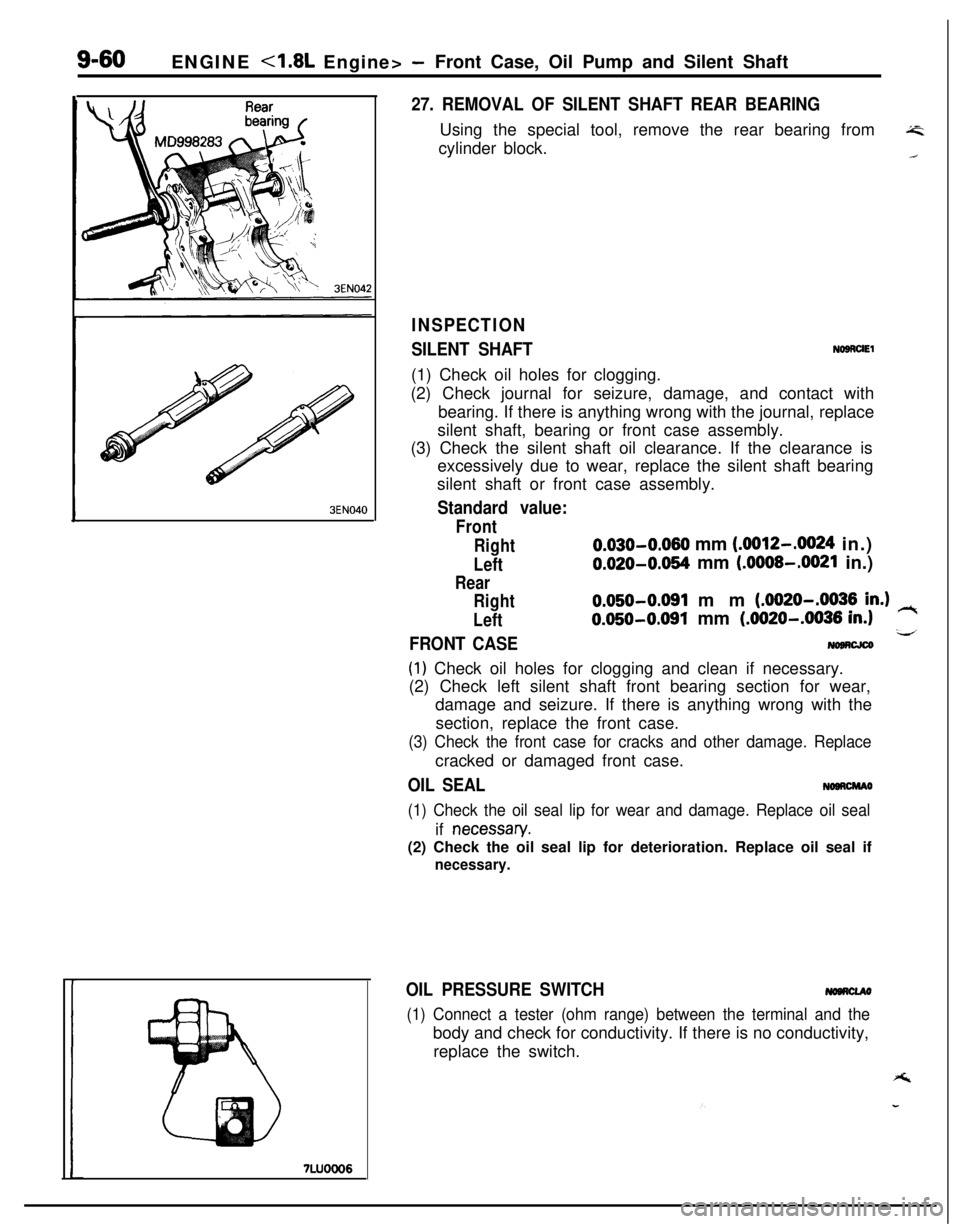
27. REMOVAL OF SILENT SHAFT REAR BEARINGUsing the special tool, remove the rear bearing from
A=cylinder block..i
INSPECTION
SILENT SHAFTNOSRUEl(1) Check oil holes for clogging.
(2) Check journal for seizure, damage, and contact with
bearing. If there is anything wrong with the journal, replace
silent shaft, bearing or front case assembly.
(3) Check the silent shaft oil clearance. If the clearance is
excessively due to wear, replace the silent shaft bearing
silent shaft or front case assembly.
Standard value:
Front
Right
0.030-0.060 mm (.0012-.0024 in.)
LeftO.O20-0.064 mm (.OOOS-.0021 in.)
Rear
Right
Left
0.050-0.091 mm (.0020-.0036 in.) rt
0.050-0.091 mm (.0020-.0036 in.1-4FRONT CASE
(1) Check oil holes for clogging and clean if necessary.
(2) Check left silent shaft front bearing section for wear,
damage and seizure. If there is anything wrong with the
section, replace the front case.
(3) Check the front case for cracks and other damage. Replacecracked or damaged front case.
OIL SEALNOORCMAO
(1) Check the oil seal lip for wear and damage. Replace oil sealif
necessan/.(2) Check the oil seal lip for deterioration. Replace oil seal if
necessary.
OIL PRESSURE SWITCH
(1) Connect a tester (ohm range) between the terminal and thebody and check for conductivity. If there is no conductivity,
replace the switch.
Page 345 of 1216
ENGINE <1.8L Engine> -Front Case, Oil Pump and Silent Shaft9-61
Fine
7LUOOO7
3LUOOOl
3LUOOO2
I
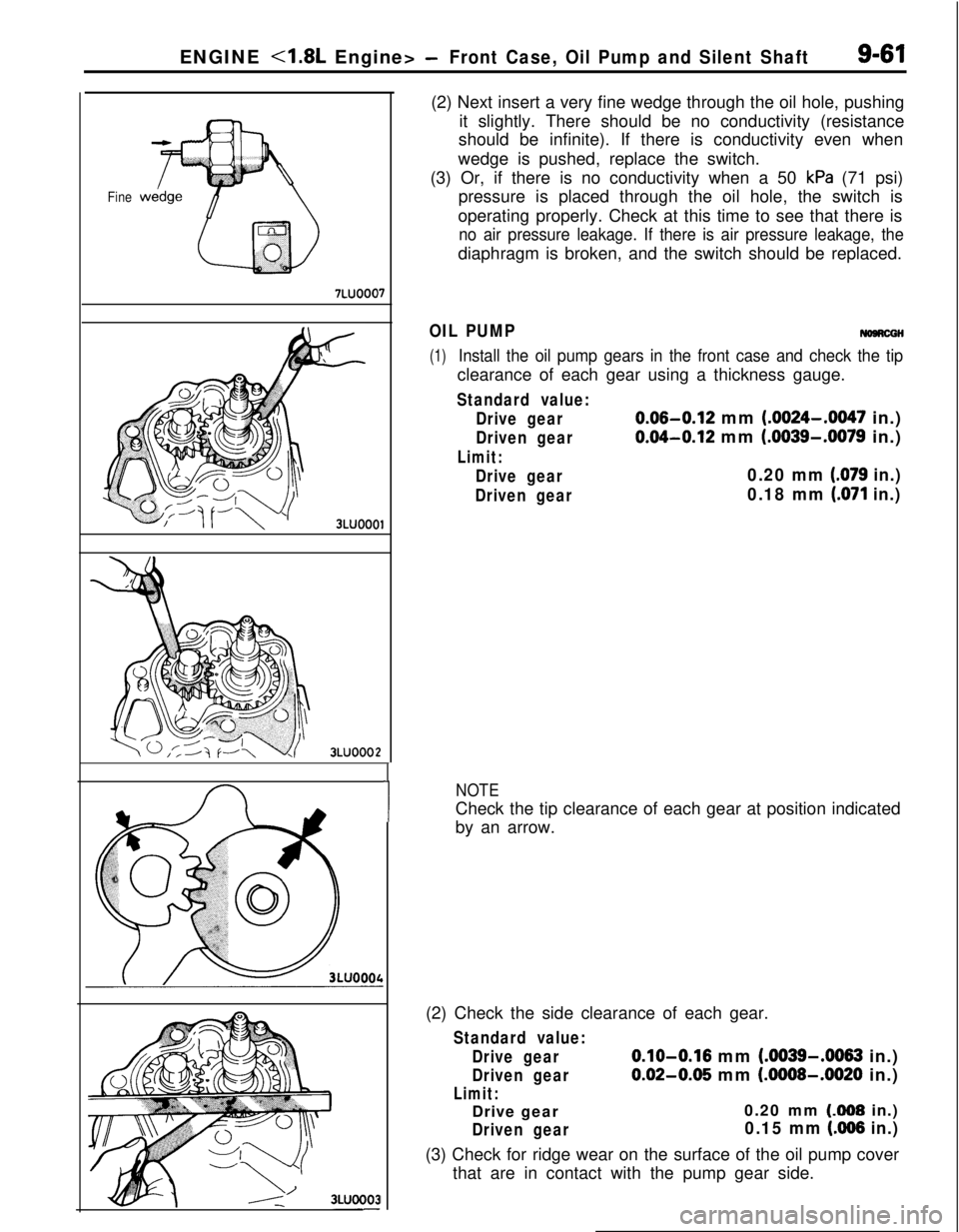
1(2) Next insert a very fine wedge through the oil hole, pushing
it slightly. There should be no conductivity (resistance
should be infinite). If there is conductivity even when
wedge is pushed, replace the switch.
(3) Or, if there is no conductivity when a 50
kPa (71 psi)
pressure is placed through the oil hole, the switch is
operating properly. Check at this time to see that there is
no air pressure leakage. If there is air pressure leakage, thediaphragm is broken, and the switch should be replaced.
OIL PUMPNomcGH
(1)Install the oil pump gears in the front case and check the tipclearance of each gear using a thickness gauge.
Standard value:
Drive gear
0.06-0.12 mm (.0024-.0047 in.)
Driven gear0.04-0.12 mm (.0039-.0079 in.)
Limit:
Drive gear0.20 mm (.079 in.)
Driven gear0.18 mm (.071 in.)
NOTECheck the tip clearance of each gear at position indicated
by an arrow.
(2) Check the side clearance of each gear.
Standard value:
Drive gear
0.10-0.16 mm (.0039-.0063 in.)
Driven gear0.02-0.05 mm (.0008-.0020 in.)
Limit:Drive gear0.20 mm (308 in.)
Driven gear0.15 mm (AI66 in.)(3) Check for ridge wear on the surface of the oil pump cover
that are in contact with the pump gear side.
Page 346 of 1216
9-62ENGINE -4.8L Engine> -Front Case, Oil Pump and Silent Shaft
OIL RELIEF PLUNGER(1) Check that the relief plunger slides smoothly.
(2) Check the relief spring for breakage.
3EN044J
MD998280
3EN270
0M D998304
SERVICE POINTS OF REASSEMBLYNOBRHAF
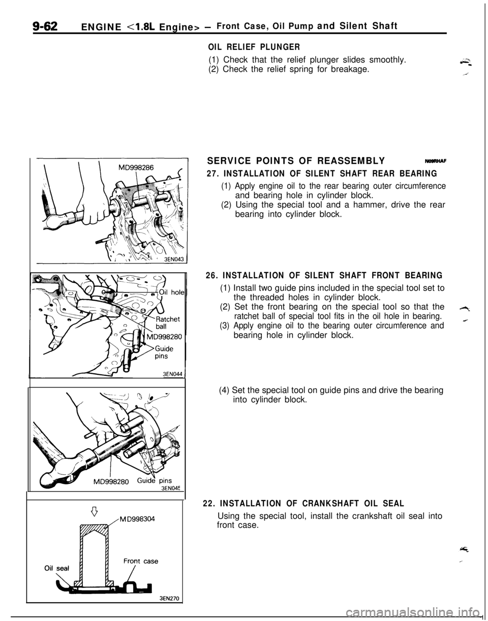
27. INSTALLATION OF SILENT SHAFT REAR BEARING
(1) Apply engine oil to the rear bearing outer circumferenceand bearing hole in cylinder block.
(2) Using the special tool and a hammer, drive the rear
bearing into cylinder block.
26. INSTALLATION OF SILENT SHAFT FRONT BEARING(1) Install two guide pins included in the special tool set to
the threaded holes in cylinder block.
(2) Set the front bearing on the special tool so that the
ratchet ball of special tool fits in the oil hole in bearing.
(3) Apply engine oil to the bearing outer circumference andbearing hole in cylinder block.
(4) Set the special tool on guide pins and drive the bearing
into cylinder block.
22. INSTALLATION OF CRANKSHAFT OIL SEALUsing the special tool, install the crankshaft oil seal into
front case.
Page 347 of 1216
ENGINE <1.8L Engine> -Front Case, Oil Pump and Silent Shaft9-63
aSocket wrench/
3EN271
MD998285R
Fasten toqether with
the timtins under cover
C
belt tensioner3ENOOWTiming marks
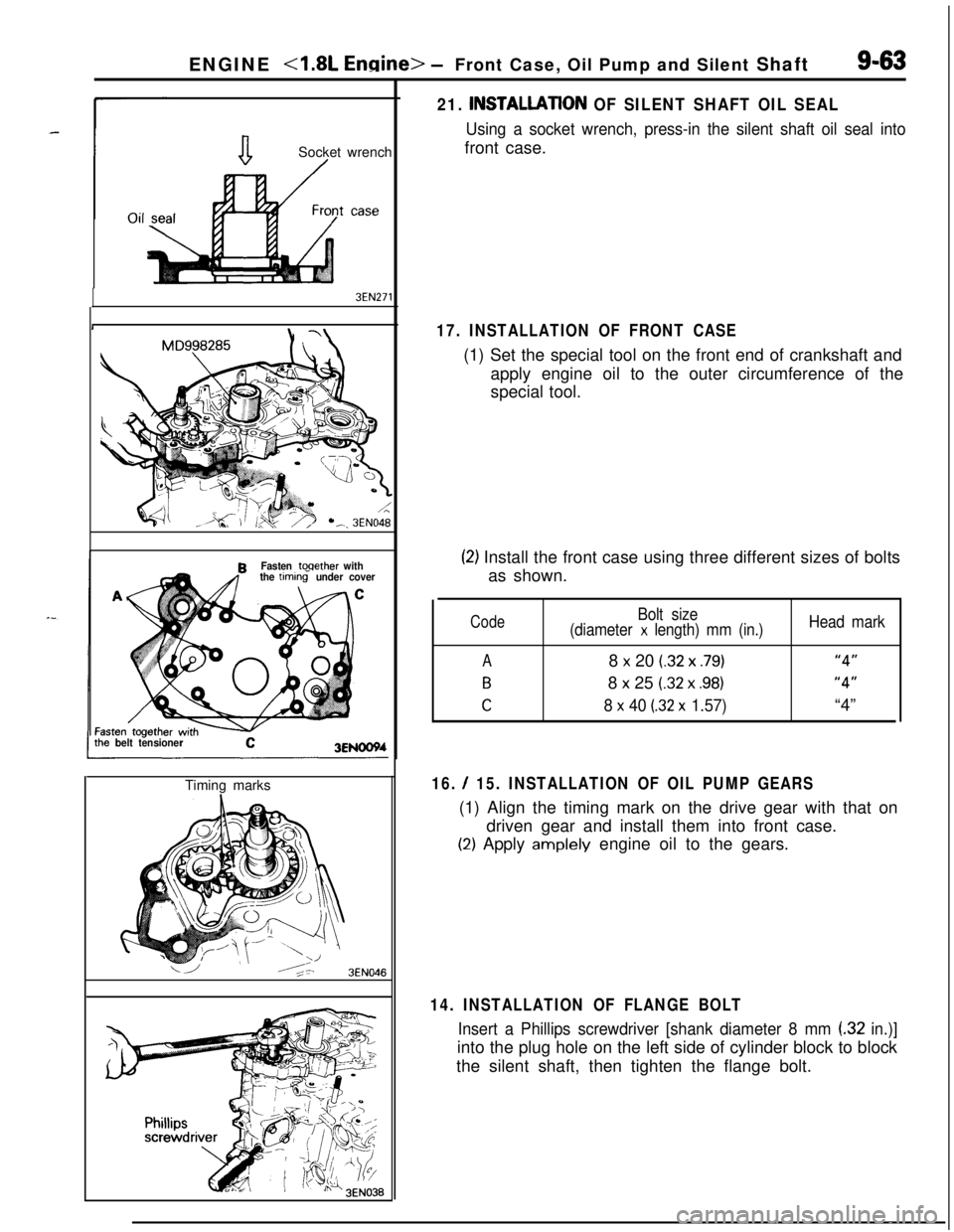
16. / 15. INSTALLATION OF OIL PUMP GEARS(1) Align the timing mark on the drive gear with that on
driven gear and install them into front case.
(2) Apply amplely engine oil to the gears.
3EN046
21. INSTALLATlON OF SILENT SHAFT OIL SEAL
Using a socket wrench, press-in the silent shaft oil seal intofront case.
17. INSTALLATION OF FRONT CASE(1) Set the special tool on the front end of crankshaft and
apply engine oil to the outer circumference of the
special tool.
(2) Install the front case using three different sizes of bolts
as shown.
Code
A
B
C
Bolt size
(diameter x length) mm (in.)8
x 20 (.32 x .79)8
x 25 (.32 x .98)
8 x 40 (32 x 1.57)
Head mark
“4”
“4”“4”
14. INSTALLATION OF FLANGE BOLT
Insert a Phillips screwdriver [shank diameter 8 mm (32 in.)]into the plug hole on the left side of cylinder block to block
the silent shaft, then tighten the flange bolt.