engine MITSUBISHI ECLIPSE 1991 Service Manual
[x] Cancel search | Manufacturer: MITSUBISHI, Model Year: 1991, Model line: ECLIPSE, Model: MITSUBISHI ECLIPSE 1991Pages: 1216, PDF Size: 67.42 MB
Page 348 of 1216
9-64ENGINE 4.8L Engine> -Front Case, Oil Pump and Silent Shaft
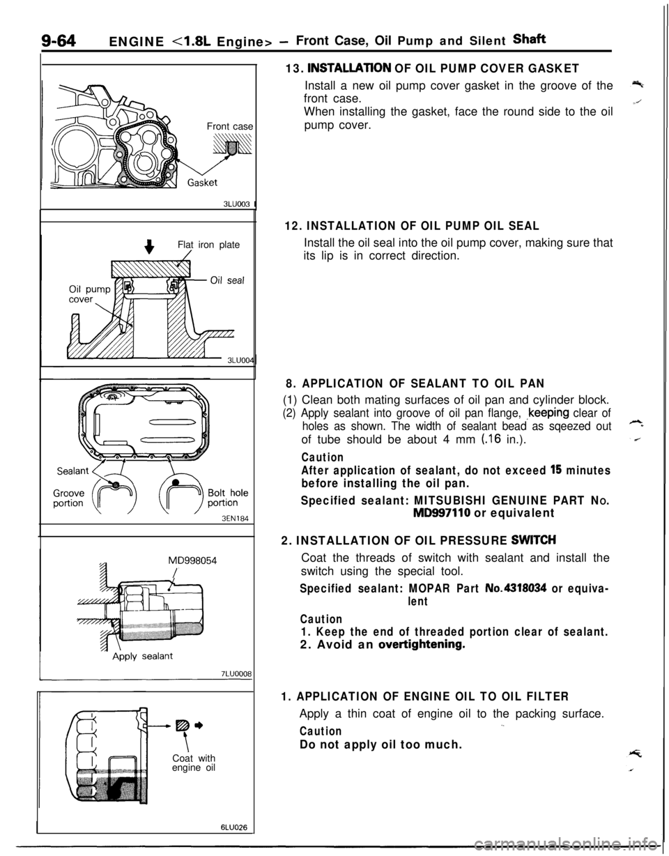
13.
INSTALLATlON OF OIL PUMP COVER GASKETInstall a new oil pump cover gasket in the groove of the
front case.
Front caseWhen installing the gasket, face the round side to the oil
pump cover.
3LUOO3 I
Flat iron plate
3EN184
MD998054
/
-----me
tCoat with
engine oil
6LUO26
12. INSTALLATION OF OIL PUMP OIL SEALInstall the oil seal into the oil pump cover, making sure that
its lip is in correct direction.
8. APPLICATION OF SEALANT TO OIL PAN(1) Clean both mating surfaces of oil pan and cylinder block.
(2) Apply sealant into groove of oil pan flange, ~keeping clear of
holes as shown. The width of sealant bead as sqeezed outof tube should be about 4 mm
(.I6 in.).
Caution
After application of sealant, do not exceed l’5 minutes
before installing the oil pan.
Specified sealant: MITSUBISHI GENUINE PART N
O.
MD997110 or equivalent
2. INSTALLATION OF OIL PRESSURE
SWlTCHCoat the threads of switch with sealant and install the
switch using the special tool.
Specified sealant: MOPAR Part No.4318034 or equiva-
lent
Caution
1. Keep the end of threaded portion clear of sealant.2. Avoid an
overtightening.
1. APPLICATION OF ENGINE OIL TO OIL FILTERApply a thin coat of engine oil to the packing surface.
,.Caution
Do not apply oil too much.
Page 349 of 1216
ENGINE <1.8L Engine> - Piston and Connecting Rod9-65
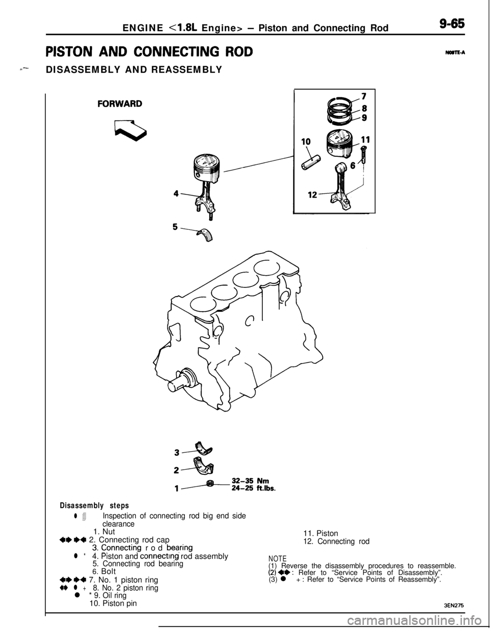
PISTON AND CONNECTING ROD
S--DISASSEMBLY AND REASSEMBLYMaTEA
Disassembly steps
l 4Inspection of connecting rod big end side
clearance1. Nut
+e I)+ 2. Connecting rod cap
3. Cpnnecting rod bearing11. Piston12. Connecting rod
l *4. Piston and connecting rod assembly5. Connecting rod bearing6. Bolt
++I)+ 7. No. 1 piston ring+e l +8. No. 2 piston ringl * 9. Oil ring10. Piston pin
NOTE(1) Reverse the disassembly procedures to reassemble.
(2) 4e : Refer to “Service Points of Disassembly”.
(3) l + : Refer to “Service Points of Reassembly”.
3EN275
Page 350 of 1216
9-66ENGINE <1.8L Engine> - Piston and Connecting Rod
DENOSC
\J5EN05;%Press down withpiston%
Piston ring
End gap6EN037SERVICE POINTS OF
DlSASSEMB&Y
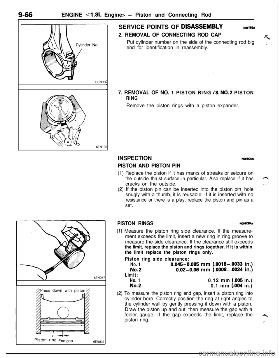
2. REMOVAL OF CONNECTING ROD CAPPut cylinder number on the side of the connecting rod big
end for identification in reassembly.
7. REMOVAL OF NO. 1 PISTON RING /8. NO.2 PISTON
RINGRemove the piston rings with a piston expander.
INSPECTION
PISTON AND PISTON PIN
NoncM(1) Replace the piston if it has marks of streaks or seizure on
the outside thrust surface in particular. Also replace if it hascracks on the outside.
(2) If the piston pin can be inserted into the piston
pink hole
snugly with a thumb, it is reusable. If it is inserted with no
resistance or there is a play, replace the piston and pin as a
set.
PISTON RINGS
(1) Measure the piston ring side clearance. If the measure-
ment exceeds the limit, insert a new ring in ring groove to
measure the side clearance. If the clearance still exceeds
the limit, replace the piston and rings together. If it is within
the limit replace the piston rings only.
Piston ring side clearance:
No. 10.045-0.085 mm (.0018-.0033 in.)
No.20.02-0.06 mm (.0008-.0024 in.)
Limit:
No. 10.12 mm (.005 in.)
No.20.1 mm (.004 in.)
(2) To measure the piston ring end gap, insert a piston ring intocylinder bore. Correctly position the ring at right angles to
the cylinder wall by gently pressing it down with a piston.
Draw the piston up and out, then measure the gap with a
feeler gauge. If the gap exceeds the limit, replace the
piston ring.
Page 351 of 1216
ENGINE <1.8L Engine>- Piston and Connecting Rod9-67
Piston ring end gap:
Standard dimension
No. 10.30-0.45 mm (.0118-.0177 in.)
No.20.20-0.35 mm (.0079-.0138 in.)
Limit0.8 mm LO31in.)
Oil ring side rail:
Standard dimension0.2-0.7 mm (.008-.028 in.)
Limit1.0 mm (.039 in.)When replacing the ring only without correcting the
cylinder bore, check the gap with the ring positioned at a
lower part of cylinder that is less worn.
When replacing a ring, be sure to use a ring of the same
size.
Piston ring service size and mark:
STDNone0.25 mm
(.OlO in.) O.S. 25
0.50 mm
(020 in.) O.S. 50
0.75 mm
(030 in.) O.S. 75
1.00 mm (039 in.) B.S.100
CONNECTION RODSNOSTCCA
(1) Replace the connecting rod if it has damage on thrust faces
at either end. Also replace the connecting rod that has ridgewear or severely rough surface on the inside diameter of
the small end.
When using a new connecting rod, the cylinder number
should be stamped in two places, on the cap and on the
rod.(2) Using a connecting rod aligner, check the rod for bend and
twist. If the measured value is close to the limit, correct therod using a press. Any connecting rod that has been
severely bent or distorted should be replaced.
Bend of connecting rod:
0.05/100 mm (.0020/3.937 in.) or less
Twist of connecting rod:
O.l/lOO mm (.004/3.937 in.) or less
SERVICE POINTS OF REASSEMBLYNOSTGEA
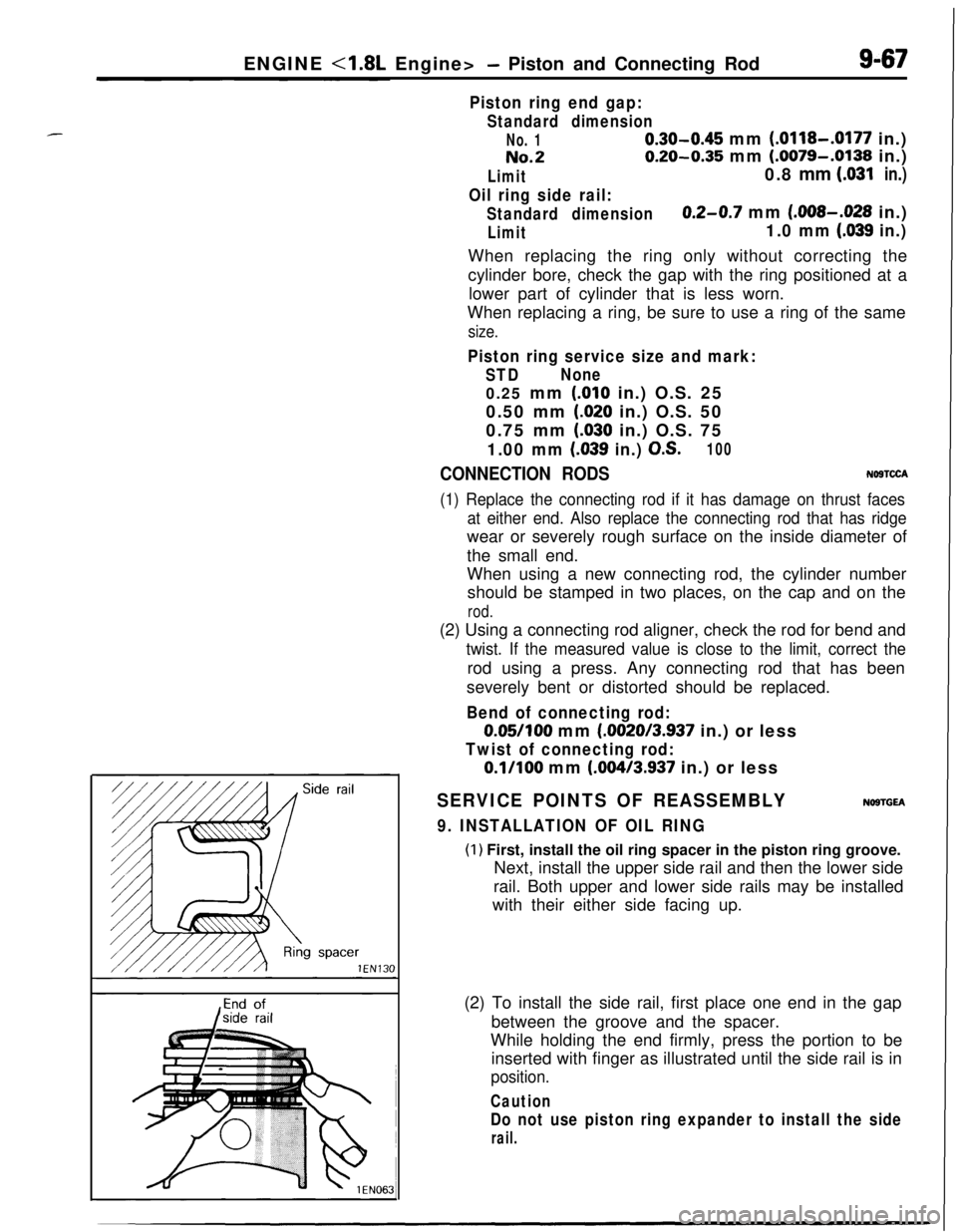
9. INSTALLATION OF OIL RING
(1) First, install the oil ring spacer in the piston ring groove.
Next, install the upper side rail and then the lower side
rail. Both upper and lower side rails may be installed
with their either side facing up.
(2) To install the side rail, first place one end in the gap
between the groove and the spacer.
While holding the end firmly, press the portion to be
inserted with finger as illustrated until the side rail is in
position.
Caution
Do not use piston ring expander to install the side
rail.
Page 352 of 1216
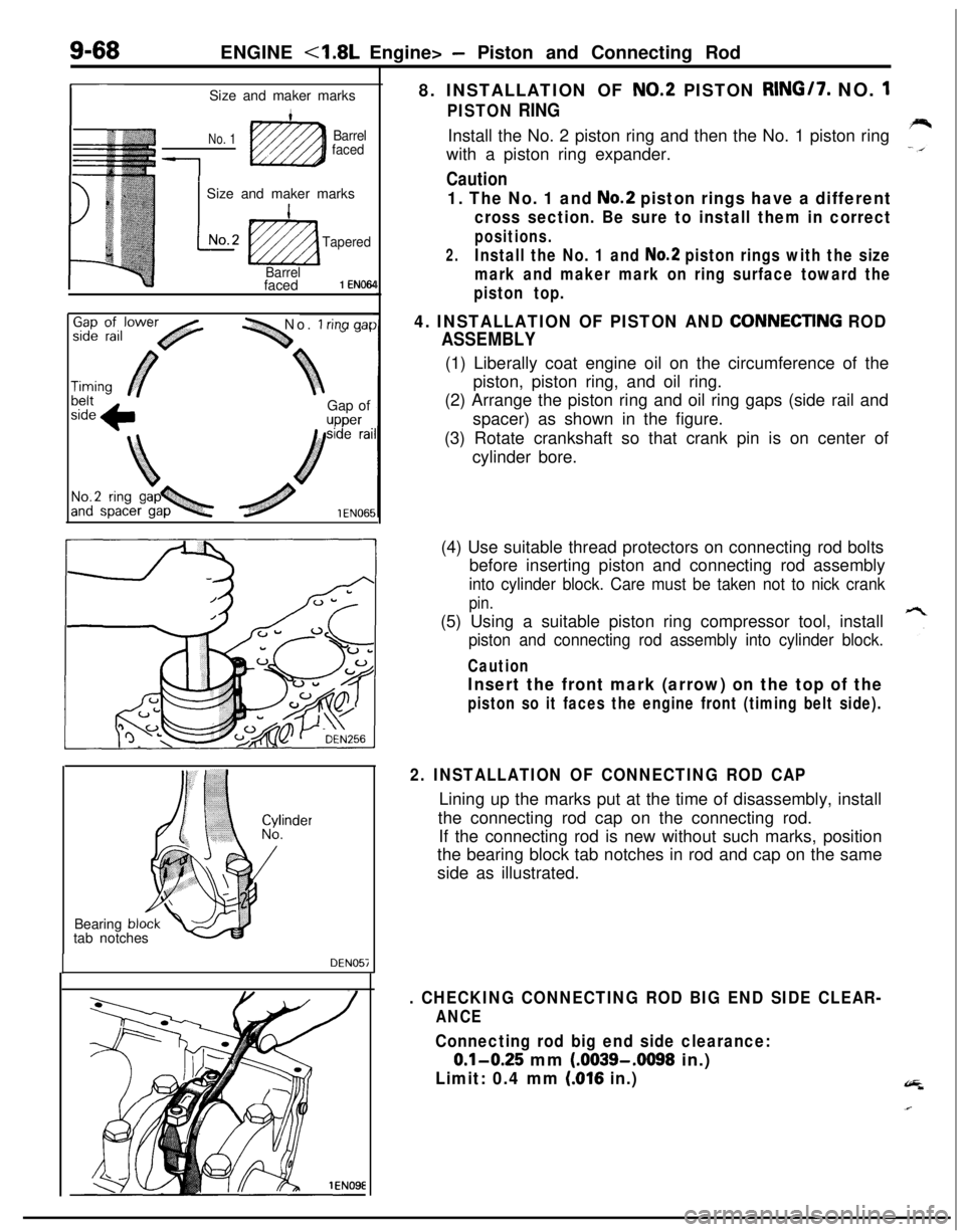
9-68ENGINE <1.8L Engine> - Piston and Connecting Rod
r-Size and maker marks
No. 1Barrel
faced
1
1 Size and maker marks
L
INo.2
ti2zza
Tapered
Barrelfaced
1 EN064
-1 No. 1 rina aarGap of
upper8. INSTALLATION OF
NO.2 PISTON RING/7. NO. 1
PISTON RINGInstall the No. 2 piston ring and then the No. 1 piston ring
with a piston ring expander.
Caution
1. The No. 1 and No.2 piston rings have a different
cross section. Be sure to install them in correct
positions.
2.Install the No. 1 and No.2 piston rings with the size
mark and maker mark on ring surface toward the
piston top.
4. INSTALLATION OF PISTON AND CONNECTlNG ROD
ASSEMBLY(1) Liberally coat engine oil on the circumference of the
piston, piston ring, and oil ring.
(2) Arrange the piston ring and oil ring gaps (side rail and
spacer) as shown in the figure.
(3) Rotate crankshaft so that crank pin is on center of
cylinder bore.
Bearing
bltab notches
DEN057(4) Use suitable thread protectors on connecting rod bolts
before inserting piston and connecting rod assembly
into cylinder block. Care must be taken not to nick crank
pin.(5) Using a suitable piston ring compressor tool, install
piston and connecting rod assembly into cylinder block.
Caution
Insert the front mark (arrow) on the top of the
piston so it faces the engine front (timing belt side).
2. INSTALLATION OF CONNECTING ROD CAPLining up the marks put at the time of disassembly, install
the connecting rod cap on the connecting rod.
If the connecting rod is new without such marks, position
the bearing block tab notches in rod and cap on the same
side as illustrated.
. CHECKING CONNECTING ROD BIG END SIDE CLEAR-
ANCE
Connecting rod big end side clearance:
0.1-0.25 mm (.0039-.0098 in.)
Limit: 0.4 mm (016 in.)
Page 353 of 1216
ENGINE <1.8L Engine> -Crankshaft, Flywheel and Drive PlateS-69
CRANKSHAFT, FLYWHEEL AND DRIVE PLATE
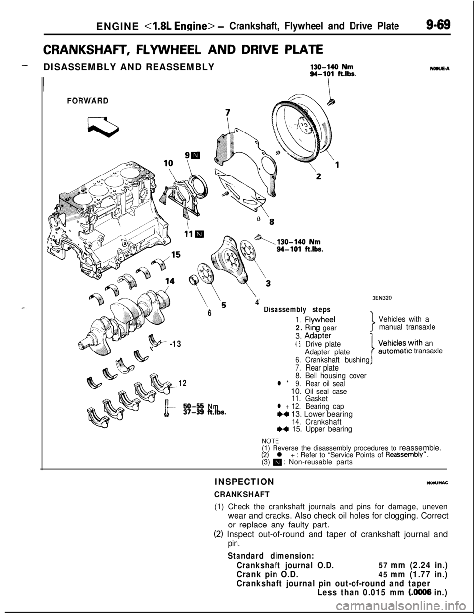
-DISASSEMBLY AND REASSEMBLY130-140 Nm94-101 fths.
II
FORWARD
6
4Disassembly steps
1. Flvwheel2.
Ri’ng gear
3.
Adaoter
NONE-A
3EN320
Vehicles with a
manual transaxle
7
?!w -134. 5.Drive plate
Adapter plate
6.Crankshaft bushing
7.Rear plate8. Bell housing cover12l *9.Rear oil seal10. Oil seal case11.Gasket50-55Nm12.37-39ft.lbs.l +BearingcapW 13. Lower bearing14.CrankshaftI)* 15. Upper bearing
IVehicles.with an
automatrctransaxle
NOTE(1) Reverse the disassembly procedures to reassemble.
(2) l + : Refer to “Service Points of Reassembly”.
(3) m : Non-reusable parts
INSPECTION
CRANKSHAFT
NOSUHAC(1) Check the crankshaft journals and pins for damage, uneven
wear and cracks. Also check oil holes for clogging. Correct
or replace any faulty part.
(2) Inspect out-of-round and taper of crankshaft journal and
pin.
Standard dimension:
Crankshaft journal O.D.
57 mm (2.24 in.)
Crank pin O.D.
45 mm (1.77 in.)
Crankshaft journal pin out-of-round and taper
Less than 0.015 mm
(.0006 in.)
Page 354 of 1216
ENGINE <1.8L Engine> -Crankshaft, Flywheel and Drive Plate
3EN055
6EN043
1 EN067
MAIN BEARINGS AND CONNECTING ROD BEARINGSVisually inspect each bearing for peeling, melt, seizure and
improper contact. Replace the faulty bearings.
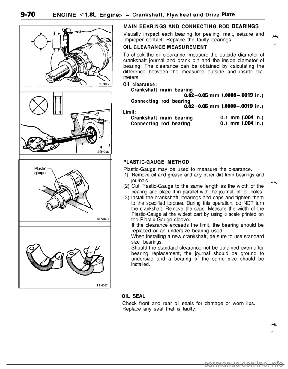
OIL CLEARANCE MEASUREMENTTo check the oil clearance, measure the outside diameter of
crankshaft journal and crank pin and the inside diameter of
bearing. The clearance can be obtained by calculating the
difference between the measured outside and inside dia-
meters.
Oil clearance:
Crankshaft main bearing
0.02-0.05 mm (.OOOS-.0019 in.)
Connecting rod bearing
0.02-0.05 mm (.OOOS-.0019 in.)
Limit:
Crankshaft main bearing0.1 mm (.004 in.)
Connecting rod bearing0.1 mm (.004 in.)
PLASTIC-GAUGE METHODPlastic-Gauge may be used to measure the clearance.
(1)Remove oil and grease and any other dirt from bearings and
journals.(2) Cut Plastic-Gauge to the same length as the width of the
bearing and place it in parallel with the journal, off oil holes.(3) Install the crankshaft, bearings and caps and tighten them
to the specified torques. During this operation, do NOT turn
the crankshaft. Remove the caps. Measure the width of the
Plastic-Gauge at the widest part by using
a scale printed onthe Plastic-Gauge sleeve.
If the clearance exceeds the limit, the bearing should be
replaced or an undersize bearing used.
When installing a new crankshaft, be sure to use standard
size bearings.Should the standard clearance not be obtained even after
bearing replacement, the journal should be ground to
undersize and a bearing of the same size should be
installed.
OIL SEALCheck front and rear oil seals for damage or worn lips.
Replace any seat that is faulty.
Page 355 of 1216
ENGINE - Crankshaft, Flwvheel and Drive Plate9-71
3EN30’lrrow mark toward
cap No,
I
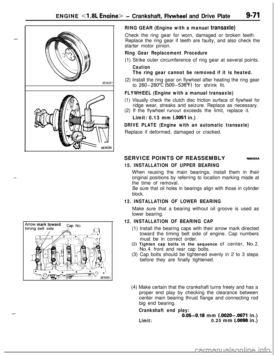
RING GEAR (Engine with a manual transaxle)Check the ring gear for worn, damaged or broken teeth.
Replace the ring gear if teeth are faulty, and also check the
starter motor pinion.
Ring Gear Replacement Procedure(1) Strike outer circumference of ring gear at several points.
Caution
The ring gear cannot be removed if it is heated.(2) Install the ring gear on flywheel after heating the ring gear
to
260-280°C (500-536°F) for shrink fit.
FLYWHEEL (Engine with a manual transaxle)
(1) Visually check the clutch disc friction surface of flywheel forridge wear, streaks and seizure. Replace as necessary.
(2) If the flywheel
runout exceeds the limit, replace it.
Limit: 0.13 mm (0051 in.)
DRIVE PLATE (Engine with an automatic transaxle)Replace if deformed, damaged or cracked.
SERVICE POINTS OF REASSEMBLY
NOSUDAA
15. INSTALLATION OF UPPER BEARINGWhen reusing the main bearings, install them in their
original positions by referring to location marking made at
the time of removal.
Be sure that oil holes in bearings align with those in cylinder
block.
13. INSTALLATION OF LOWER BEARINGMake sure that a bearing without oil groove is used as
lower bearing.
12. INSTALLATION OF BEARING CAP(1) Install the bearing caps with their arrow mark directed
toward the timing belt side of engine. Cap numbers
must be in correct order.(2) Tighten cap bolts in the sequence of center,
No.2,
No.4. front and rear cap bolts.
(3) Cap bolts should be tightened evenly in 2 to 3 steps
before they are finally tightened.
(4) Make certain that the crankshaft turns freely and has a
proper end play by checking the clearance between
center main bearing thrust flange and connecting rod
big end bearing.
Crankshaft end play:
0.05-0.18 mm (.0020-.0071 in.)
Limit:0.25 mm (.0098 in.)
Page 356 of 1216
9-72ENGINE <1.8L Engine> -Crankshaft, Flywheel and Drive Plate/Cylinder Block
PressOil seal
I
MD99801 1
/
Oil seal case1 EN06L
CYLINDER BLOCK
i//
199.
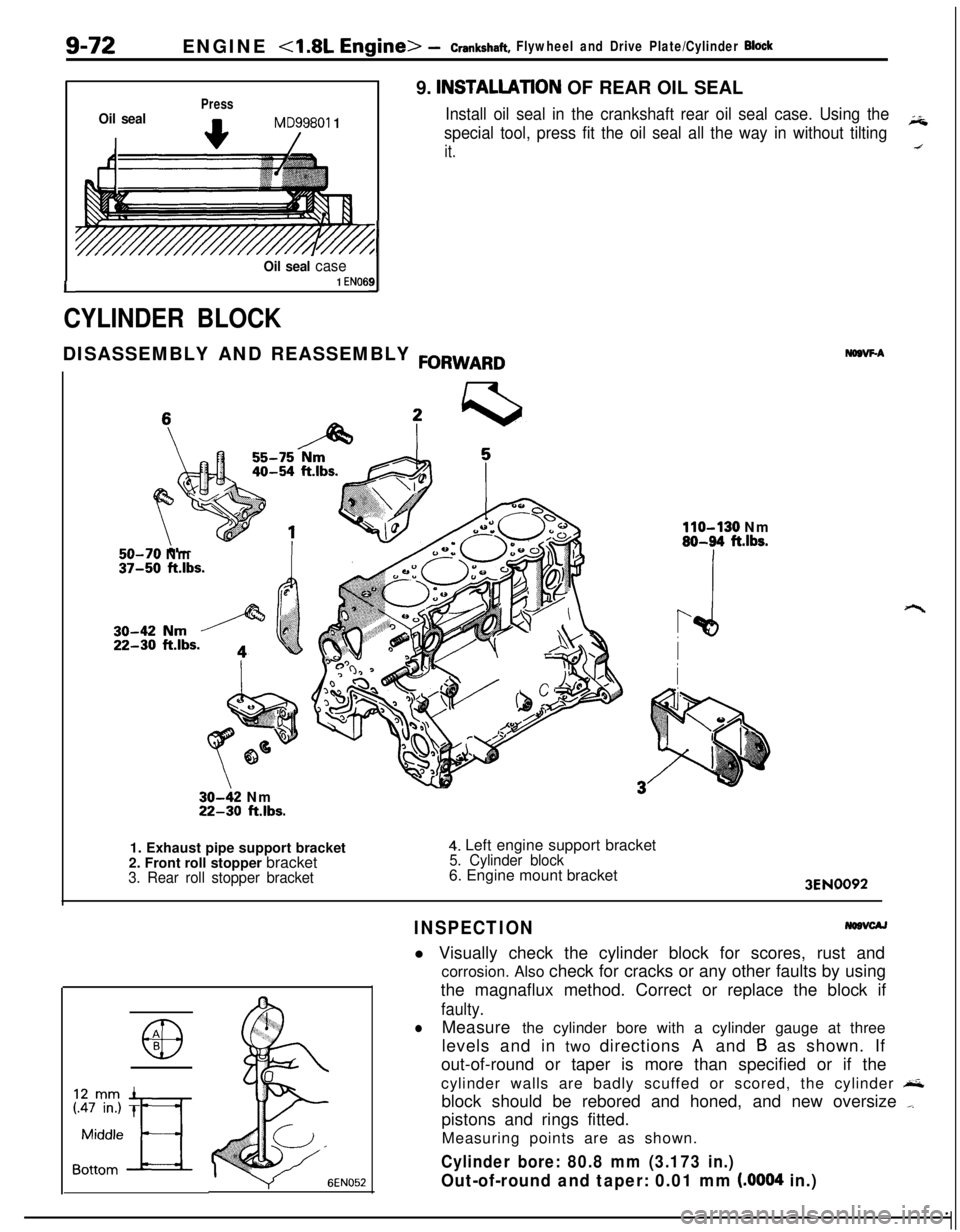
INSTALLATlON OF REAR OIL SEAL
Install oil seal in the crankshaft rear oil seal case. Using the
special tool, press fit the oil seal all the way in without tiltingiii
it.DISASSEMBLY AND REASSEMBLY
FORWARD
50-70 Nm37-50 ft.lbs.
30-42 Nm22-30 ft.lbs.
NDBVF-A
110-130 Nm80-94 ft.lbs.1. Exhaust pipe support bracket
2. Front roll stopper bracket
3. Rear roll stopper bracket
4. Left engine support bracket5. Cylinder block6. Engine mount bracket
3EN0092
INSPECTIONl Visually check the cylinder block for scores, rust and
corrosion. Also check for cracks or any other faults by using
the magnaflux method. Correct or replace the block if
faulty.
lMeasure the cylinder bore with a cylinder gauge at three
levels and in two directions A and
B as shown. If
out-of-round or taper is more than specified or if the
cylinder walls are badly scuffed or scored, the cylinder
&block should be rebored and honed, and new oversize
_pistons and rings fitted.
Measuring points are as shown.
Cylinder bore: 80.8 mm (3.173 in.)
Out-of-round and taper: 0.01 mm (.0004 in.)
Page 357 of 1216
ENGINE <1.8L Engine> - Cylinder Block9-73
lIf cylinder top ridge is worn in stages, smooth out with a
ridge reamer.
l Oversize pistons are available in four sizes.
Piston oversizes and marks:0.25 mm
(.OlO in.) OS. 0.25
0.50 mm
(.020 in.) O.S. 0.50
0.75 mm
(.030 in.) O.S. 0.75
1
.OO mm (.039 in.) O.S. 1.00
lTo rebore the cylinder to an oversize, keep the specified
clearance between the oversize piston and the bore, and
make sure that all pistons used are of the same oversize.
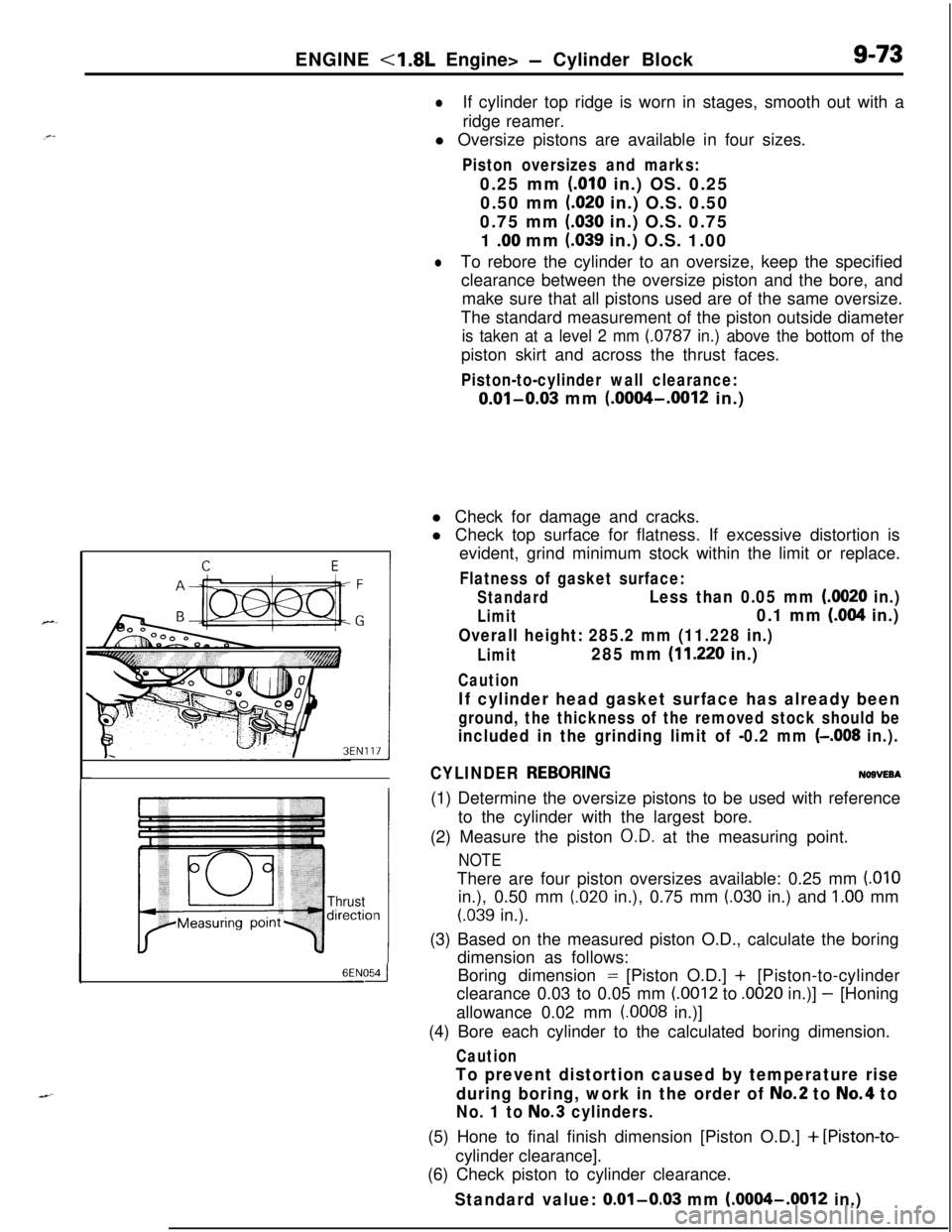
The standard measurement of the piston outside diameter
is taken at a level 2 mm (0787 in.) above the bottom of thepiston skirt and across the thrust faces.
Piston-to-cylinder wall clearance:
0.01-0.03 mm (.0004-.0012 in.)
Thrustdirectiol
6ENOdl Check for damage and cracks.
l Check top surface for flatness. If excessive distortion is
evident, grind minimum stock within the limit or replace.
Flatness of gasket surface:
StandardLess than 0.05 mm (0020 in.)
Limit0.1 mm (.004 in.)
Overall height: 285.2 mm (11.228 in.)
Limit285 mm (11.220 in.)
Caution
If cylinder head gasket surface has already been
ground, the thickness of the removed stock should be
included in the grinding limit of -0.2 mm (-.008 in.).
CYLINDER
REBORINGNOBVEBA(1) Determine the oversize pistons to be used with reference
to the cylinder with the largest bore.
(2) Measure the piston
O.D. at the measuring point.
NOTEThere are four piston oversizes available: 0.25 mm
(.OlOin.), 0.50 mm
(.020 in.), 0.75 mm (.030 in.) and 1.00 mm
(.039 in.).
(3) Based on the measured piston O.D., calculate the boring
dimension as follows:
Boring dimension = [Piston O.D.] + [Piston-to-cylinder
clearance 0.03 to 0.05 mm
(.0012 to .0020 in.)] - [Honing
allowance 0.02 mm
(.0008 in.)]
(4) Bore each cylinder to the calculated boring dimension.
Caution
To prevent distortion caused by temperature rise
during boring, work in the order of
No.2 to No.4 to
No. 1 to No.3 cylinders.(5) Hone to final finish dimension [Piston O.D.]
+ [Piston-to-cylinder clearance].
(6) Check piston to cylinder clearance.
Standard value: 0.01-0.03 mm (.0004-.0012 in.)