ECU MITSUBISHI ECLIPSE 1991 User Guide
[x] Cancel search | Manufacturer: MITSUBISHI, Model Year: 1991, Model line: ECLIPSE, Model: MITSUBISHI ECLIPSE 1991Pages: 1216, PDF Size: 67.42 MB
Page 60 of 1216
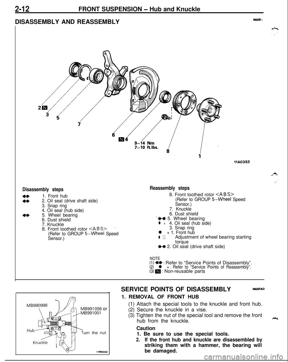
2-12FRONT SUSPENSION - Hub and Knuckle
DISASSEMBLY AND REASSEMBLY
N02lE--
Disassembly steps
:t
1. Front hub
2. Oil seal (drive shaft side)
3. Snap ring
4. Oil seal (hub side)
5. Wheel bearing6. Dust shield
7. Knuckle
8. Front toothed rotor
’
(Refer to GROUP 5-Wheel Speed
Sensor.)
llA0353
Reassembly steps8. Front toothed rotor
(Refer to GROUP 5-Wheel Speed
Sensor.)
7. Knuckle6. Dust shield
‘.++ 5. Wheel bearingl +4. Oil seal (hub side)
3. Snap ring
l + 1. Front hub
l *Adjustment of wheel bearing starting
torque
~~ 2. Oil seal (drive shaft side)
NOTE(1) +e : Refer to “Service Points of Disassembly”.(2) l + : Refer to “Service Points of Reassembly”.(3) m : Non-reusable parts
MB991 056 or
11uo050SERVICE POINTS OF DISASSEMBLY
NO2lFAO-1. REMOVAL OF FRONT HUB
(1) Attach the special tools to the knuckle and front hub.
(2) Secure the knuckle in a vise.
(3) Tighten the nut of the special tool and remove the front
hub from the knuckle.
Caution
1. Be sure to use the special tools.
2.If the front hub and knuckle are disassembled bystriking them with a hammer, the bearing will
be damaged.
Page 65 of 1216
FRONT SUSPENSION - Drive Shaft247Pry bar
13E526
12RO426Cotter pin
/
/HubllR0015
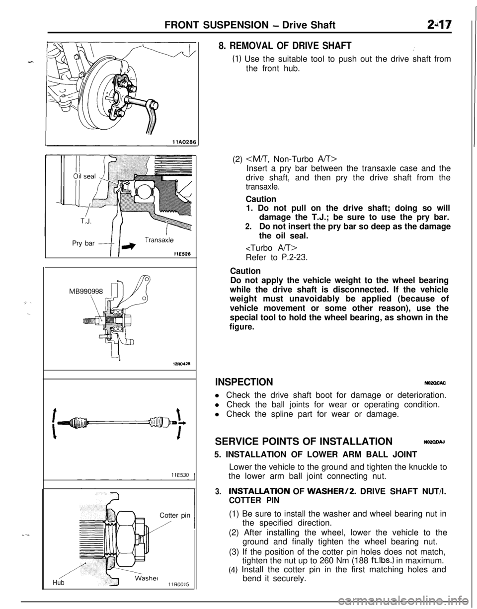
8. REMOVAL OF DRIVE SHAFT.’
(1) Use the suitable tool to push out the drive shaft from
the front hub.
(2)
Insert a pry bar between the transaxle case and the
drive shaft, and then pry the drive shaft from the
transaxle.Caution
1. Do not pull on the drive shaft; doing so will
damage the T.J.; be sure to use the pry bar.
2.Do not insert the pry bar so deep as the damage
the oil seal.
P.2-23.Caution
Do not apply the vehicle weight to the wheel bearing
while the drive shaft is disconnected. If the vehicle
weight must unavoidably be applied (because of
vehicle movement or some other reason), use the
special tool to hold the wheel bearing, as shown in the
figure.
INSPECTIONN62CXACl Check the drive shaft boot for damage or deterioration.
l Check the ball joints for wear or operating condition.
l Check the spline part for wear or damage.
SERVICE POINTS OF INSTALLATION
N62aoAJ5. INSTALLATION OF LOWER ARM BALL JOINT
Lower the vehicle to the ground and tighten the knuckle to
the lower arm ball joint connecting nut.
3.INSTALLATlON OF WASHER/2. DRIVE SHAFT NUT/l.
COTTER PIN(1) Be sure to install the washer and wheel bearing nut in
the specified direction.
(2) After installing the wheel, lower the vehicle to the
ground and finally tighten the wheel bearing nut.
(3) If the position of the cotter pin holes does not match,
tighten the nut up to 260 Nm (188
ft.lbs.) in maximum.
(4) Install the cotter pin in the first matching holes and
bend it securely.
Page 68 of 1216
FRONT SUSPENSION - Drive Shaft
IllA0127
llE560
Grease
llE563
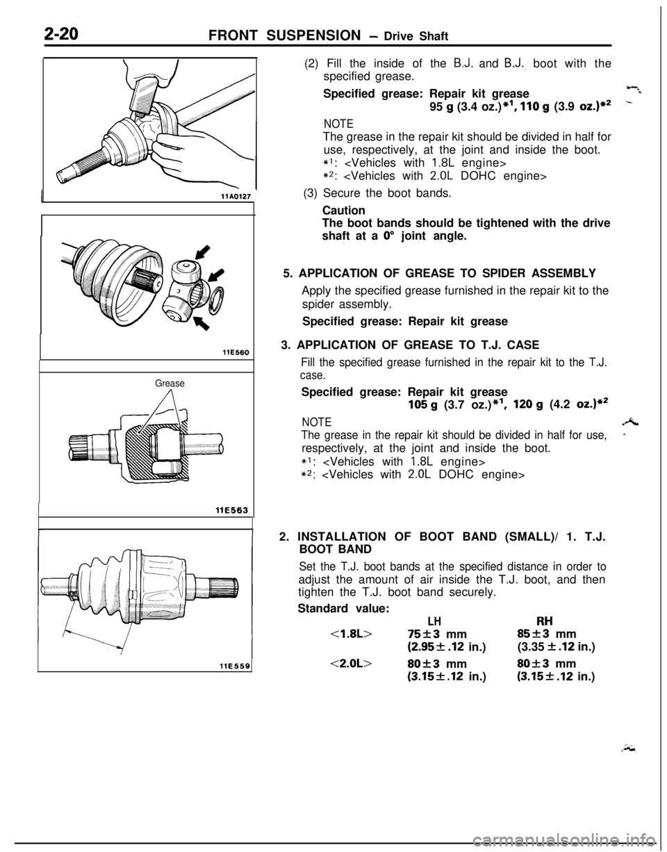
llE559(2) Fill the inside of the
B.J. and B.J., boot with the
specified grease.
Specified grease: Repair kit grease
Wil95
g (3.4 oz.)*I, 110 g (3.9 oz.)**-
NOTEThe grease in the repair kit should be divided in half for
use, respectively, at the joint and inside the boot.
*I:
*2:
(3) Secure the boot bands.
Caution
The boot bands should be tightened with the drive
shaft at a
0” joint angle.
5. APPLICATION OF GREASE TO SPIDER ASSEMBLY
Apply the specified grease furnished in the repair kit to the
spider assembly.
Specified grease: Repair kit grease
3. APPLICATION OF GREASE TO T.J. CASE
Fill the specified grease furnished in the repair kit to the T.J.
case.Specified grease: Repair kit grease
105 g (3.7 oz.)*‘I,120 g (4.2 oz.)**
NOTEA
The grease in the repair kit should be divided in half for use,-respectively, at the joint and inside the boot.
*I:
*2:
2. INSTALLATION OF BOOT BAND (SMALL)/ 1. T.J.
BOOT BAND
Set the T.J. boot bands at the specified distance in order toadjust the amount of air inside the T.J. boot, and then
tighten the T.J. boot band securely.
Standard value:
LHRH
(2.95f .I2 in.)(3.35 f .I2 in.)
<2.0L>80f3 mmSO+3 mm
(3.15f.12 in.)(3.15+ .I2 in.)
Page 74 of 1216
2-26FRONT SUSPENSION - Drive Shaft
llE560
INSPECTIONN02QGEB
0
0
0
0Check the dust cover for damage or deterioration.Check the drive shaft for damage, bending or corrosion.
Check the inner shaft for damage, bending or corrosion.
-Check the drive shaft spline part for wear or damage.
=-Check the inner shaft spline for wear or damage.
Check for entry of water and/or foreign material into
B-J..Check the spider assembly for roller rotation, wear or
corrosion.Check the groove inside T.J. case for wear of corrosion.
Check the boots for deterioration, damage or cracking.
Check the center bearing for seizure, discoloration or
roughness of rolling surface.
SERVICE POINTS OF REASSEMBLY
NOZQHEEa
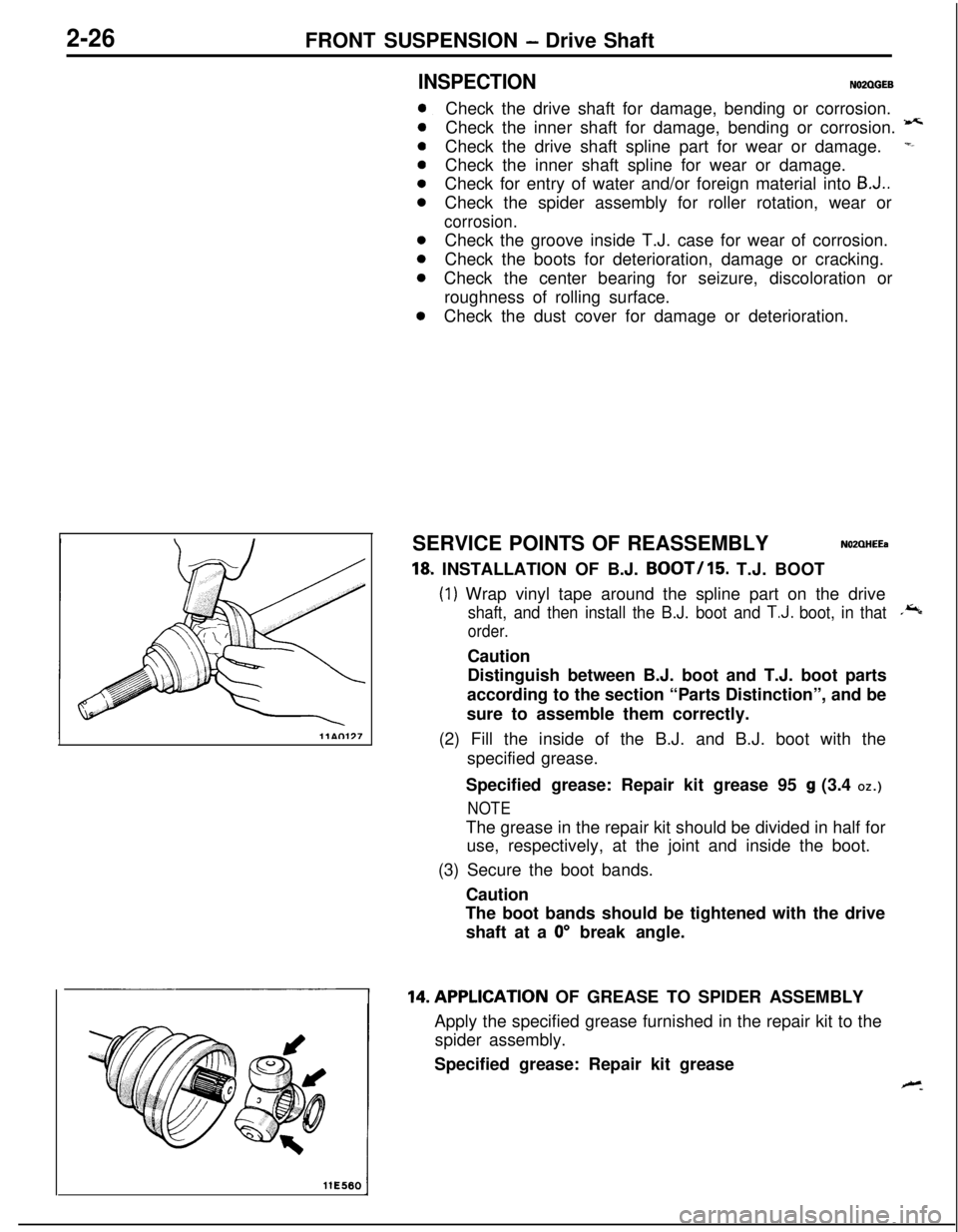
18, INSTALLATION OF B.J. BOOT/15. T.J. BOOT
(1) Wrap vinyl tape around the spline part on the drive
shaft, and then install the B.J. boot and T.J. boot, in that.*
order.Caution
Distinguish between B.J. boot and T.J. boot parts
according to the section “Parts Distinction”, and be
sure to assemble them correctly.
(2) Fill the inside of the B.J. and B.J. boot with the
specified grease.
Specified grease: Repair kit grease 95
g (3.4 OZ.)
NOTEThe grease in the repair kit should be divided in half for
use, respectively, at the joint and inside the boot.
(3) Secure the boot bands.
Caution
The boot bands should be tightened with the drive
shaft at a
0” break angle.14.APPLlCATlON OF GREASE TO SPIDER ASSEMBLY
Apply the specified grease furnished in the repair kit to the
spider assembly.
Specified grease: Repair kit grease
Page 76 of 1216
2-28FRONT SUSPENSION - Drive Shaft
Inner shaft
llA0083
1T.J. case.,
MB9909383%QilD998801
r
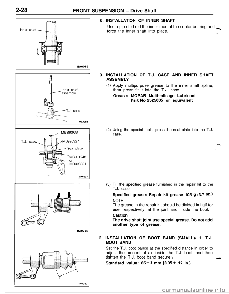
IHA00876. INSTALLATION OF INNER SHAFT
Use a pipe to hold the inner race of the center bearing and
“4force the inner shaft into place.
.a3. INSTALLATION OF T.J. CASE AND INNER SHAFT
ASSEMBLY
(1) Apply multipurpose grease to the inner shaft spline,
then press fit it into the T.J. case.
Grease: MOPAR Multi-mileage Lubricant
Part No.2525035 or equivalent
(2) Using the special tools, press the seal plate into the T.J.
case.
(3) Fill the specified grease furnished in the repair kit to the
T.J. case.Specified grease: Repair kit grease 105
g (3.7 oz.1
NOTEThe grease in the repair kit should be divided in half for
use, respectively, at the joint and inside the boot.
Caution
The drive shaft joint use special grease. Do not add
another type of grease.
2. INSTALLATION OF BOOT BAND (SMALL)/ 1. T.J.
BOOT BAND
Set the T.J. boot bands at the specified distance in order toadjust the amount of air inside the T.J. boot, and then
tighten the T.J. boot band securely.
eStandard value:
85f3 mm (3.35+ .12 in.)
Page 83 of 1216
FRONT SUSPENSION - Lower Arm2-35
12UOO18SERVICE POINTS OF REMOVAL
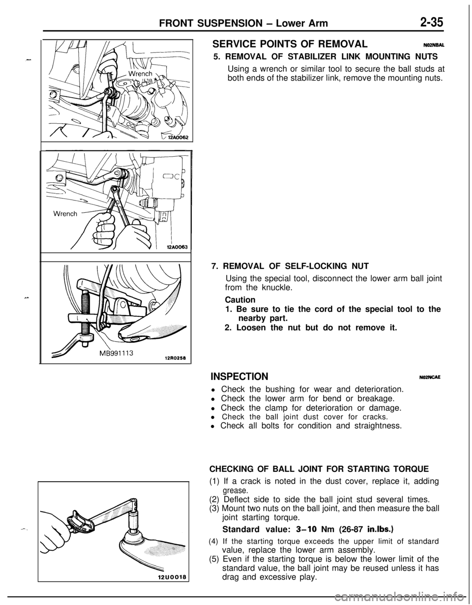
NOZNSAL5. REMOVAL OF STABILIZER LINK MOUNTING NUTS
Using a wrench or similar tool to secure the ball studs at
both ends of the stabilizer link, remove the mounting nuts.
7. REMOVAL OF SELF-LOCKING NUT
Using the special tool, disconnect the lower arm ball joint
from the knuckle.
Caution
1. Be sure to tie the cord of the special tool to the
nearby part.
2. Loosen the nut but do not remove it.
INSPECTIONNOZNCAEl Check the bushing for wear and deterioration.
l Check the lower arm for bend or breakage.
l Check the clamp for deterioration or damage.
l Check the ball joint dust cover for cracks.
l Check all bolts for condition and straightness.
CHECKING OF BALL JOINT FOR STARTING TORQUE
(1) If a crack is noted in the dust cover, replace it, adding
grease.(2) Deflect side to side the ball joint stud several times.
(3) Mount two nuts on the ball joint, and then measure the ball
joint starting torque.
Standard value:
3-10 Nm (26-87 in.lbs.)(4) If the starting torque exceeds the upper limit of standard
value, replace the lower arm assembly.
(5) Even if the starting torque is below the lower limit of the
standard value, the ball joint may be reused unless it has
drag and excessive play.
Page 84 of 1216
2-36FRONT SUSPENSION - Lower Arm
Lips
/IDust
cover
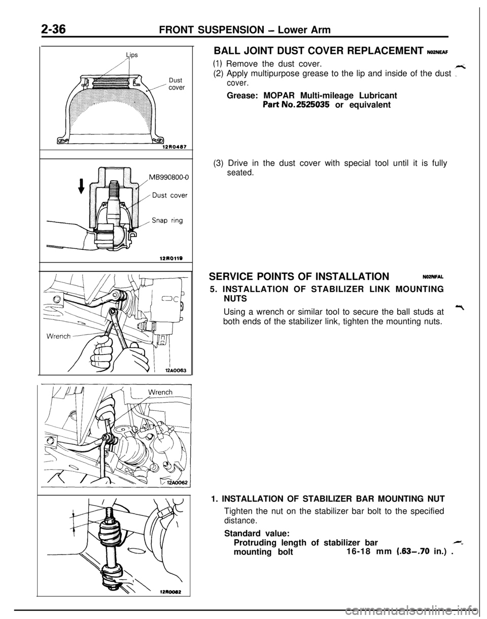
12R0487BALL JOINT DUST COVER REPLACEMENT
NOZNEAF
(1) Remove the dust cover.
(2) Apply multipurpose grease to the lip and inside of the dust
7
cover.Grease: MOPAR Multi-mileage Lubricant
Part No.2525035 or equivalent
(3) Drive in the dust cover with special tool until it is fully
seated.SERVICE POINTS OF INSTALLATION
NOZNFAL5. INSTALLATION OF STABILIZER LINK MOUNTING
NUTS
Using a wrench or similar tool to secure the ball studs at
Tboth ends of the stabilizer link, tighten the mounting nuts.
1. INSTALLATION OF STABILIZER BAR MOUNTING NUT
Tighten the nut on the stabilizer bar bolt to the specified
distance.Standard value:
Protruding length of stabilizer bar
.M”mounting bolt16-18 mm
(.63-.70 in.) .
Page 87 of 1216
FRONT SUSPENSION - Stabilizer Bar2-39SERVICE POINTS OF REMOVAL
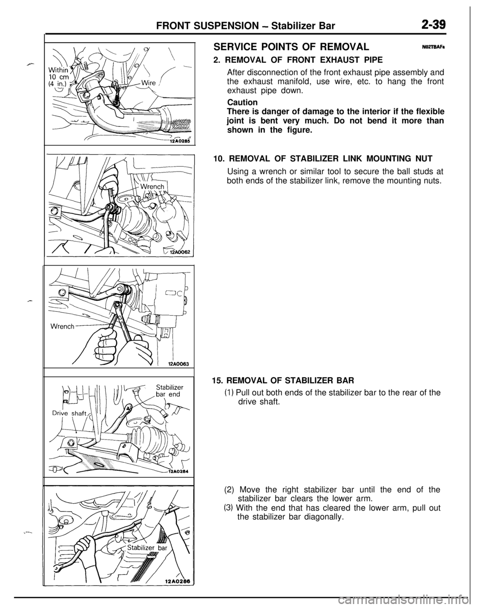
NOZTBAFa2. REMOVAL OF FRONT EXHAUST PIPE
After disconnection of the front exhaust pipe assembly and
the exhaust manifold, use wire, etc. to hang the front
exhaust pipe down.
Caution
There is danger of damage to the interior if the flexible
joint is bent very much. Do not bend it more than
shown in the figure.
10. REMOVAL OF STABILIZER LINK MOUNTING NUT
Using a wrench or similar tool to secure the ball studs at
both ends of the stabilizer link, remove the mounting nuts.
15. REMOVAL OF STABILIZER BAR
(1) Pull out both ends of the stabilizer bar to the rear of the
drive shaft.
(2) Move the right stabilizer bar until the end of the
stabilizer bar clears the lower arm.
(3) With the end that has cleared the lower arm, pull out
the stabilizer bar diagonally.
Page 88 of 1216
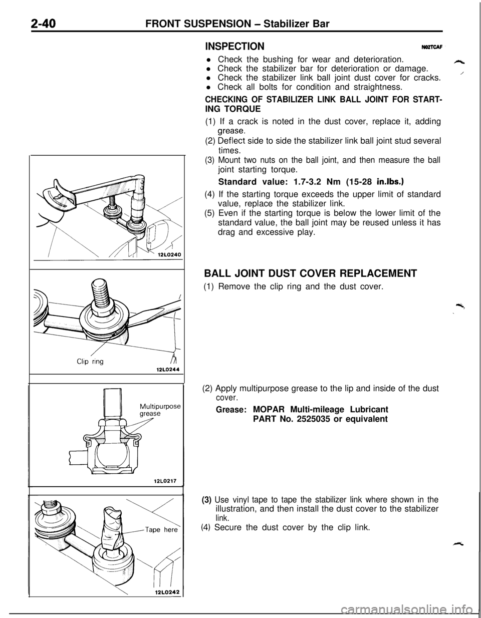
12LO244Z-40FRONT SUSPENSION - Stabilizer Bar
INSPECTIONNO2TCAFl Check the bushing for wear and deterioration.
l Check the stabilizer bar for deterioration or damage.
l Check the stabilizer link ball joint dust cover for cracks.
l Check all bolts for condition and straightness.
CHECKING OF STABILIZER LINK BALL JOINT FOR START-ING TORQUE
(1) If a crack is noted in the dust cover, replace it, adding
(2)
~~f~~~t side to side the stabilizer link ball joint stud several
times.
(3) Mount two nuts on the ball joint, and then measure the balljoint starting torque.
Standard value: 1.7-3.2 Nm (15-28
in.lbs.)(4) If the starting torque exceeds the upper limit of standard
value, replace the stabilizer link.
(5) Even if the starting torque is below the lower limit of the
standard value, the ball joint may be reused unless it has
drag and excessive play.
12LO217
12LQ242-BALL JOINT DUST COVER REPLACEMENT
(1) Remove the clip ring and the dust cover.
(2) Apply multipurpose grease to the lip and inside of the dust
cover.
Grease:MOPAR Multi-mileage Lubricant
PART No. 2525035 or equivalent
(3) Use vinyltape to tape the stabilizer link where shown in theillustration, and then install the dust cover to the stabilizer
link.
(4.) Secure the dust cover by the clip link.
rt
/
Page 89 of 1216
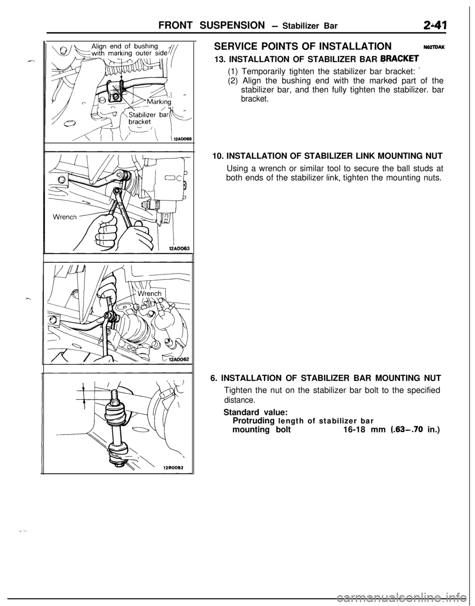
FRONT SUSPENSION - Stabilizer Bar241
3 *!-Marking
A I I\/\ \lZAOOOESERVICE POINTS OF INSTALLATION
NO2lDAK13. INSTALLATION OF STABILIZER BAR
FRACKET(1) Temporarily tighten the stabilizer bar bracket:
’(2) Align the bushing end with the marked part of the
stabilizer bar, and then fully tighten the stabilizer. bar
bracket.10. INSTALLATION OF STABILIZER LINK MOUNTING NUT
Using a wrench or similar tool to secure the ball studs at
both ends of the stabilizer
link, tighten the mounting nuts.
6. INSTALLATION OF STABILIZER BAR MOUNTING NUT
Tighten the nut on the stabilizer bar bolt to the specified
distance.Standard value:
Protruding length of stabilizer bar
mounting bolt16-18 mm
(.63-.70 in.)