ECU MITSUBISHI ECLIPSE 1991 Owner's Manual
[x] Cancel search | Manufacturer: MITSUBISHI, Model Year: 1991, Model line: ECLIPSE, Model: MITSUBISHI ECLIPSE 1991Pages: 1216, PDF Size: 67.42 MB
Page 91 of 1216
FRONT SUSPENSION - Stabilizer Bar2-43SERVICE POINTS OF REMOVAL
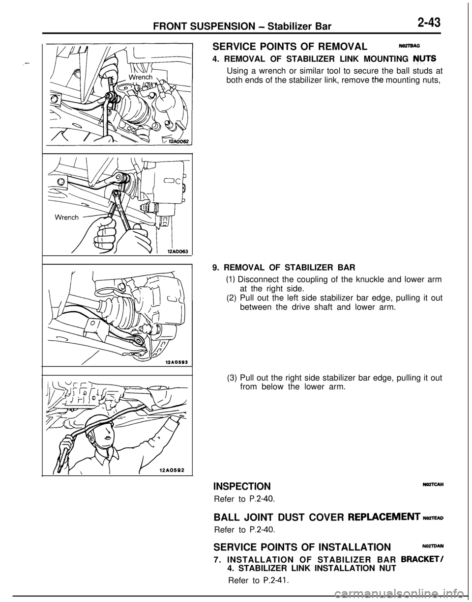
NOZlBAG4. REMOVAL OF STABILIZER LINK MOUNTING NUTS
Using a wrench or similar tool to secure the ball studs at
both ends of the stabilizer link, remove tfie mounting nuts,
19. REMOVAL OF STABILIZER BAR
(1) Disconnect the coupling of the knuckle and lower arm
at the right side.
(2) Pull out the left side stabilizer bar edge, pulling it out
between the drive shaft and lower arm.
(3) Pull out the right side stabilizer bar edge, pulling it out
from below the lower arm.
INSPECTIONRefer to
P.2-40.
NOZTCAHBALL JOINT DUST COVER
REPLACEMENTNomDRefer to
P.2-40.SERVICE POINTS OF INSTALLATION
NOZTDAN7. INSTALLATION OF STABILIZER BAR
BRACKET!4. STABILIZER LINK INSTALLATION NUT
Refer to
P.2-41.
Page 113 of 1216
12A0611
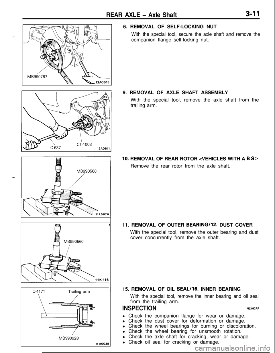
REAR AXLE - Axle Shaft3-116. REMOVAL OF SELF-LOCKING NUT
With the special tool, secure the axle shaft and remove thecompanion flange self-locking nut.
9. REMOVAL OF AXLE SHAFT ASSEMBLY
With the special tool, remove the axle shaft from the
trailing arm.
10. REMOVAL OF REAR ROTOR
111. REMOVAL OF OUTER BEARING/lZ. DUST COVER
With the special tool, remove the outer bearing and dust
cover concurrently from the axle shaft.
115. REMOVAL OF OIL SEAL/lG. INNER BEARING
MB990560
/Trailing arm
/
/MB99092811
A0038
With the special tool, remove the inner bearing and oil sealfrom the trailing arm.
INSPECTIONNOBHCAFl Check the companion flange for wear or damage.
l Check the dust cover for deformation or damage.
l Check the wheel bearings for burning or discoloration.
l Check the wheel bearing for unsmooth rotation.
l Check the axle shaft for cracking, wear or damage.
l Check oil seal for cracking or damage.
Page 115 of 1216
REAR AXLE - Axle Shaft/Drive Shaft3-13
DRIVE SHAFTN03JA--
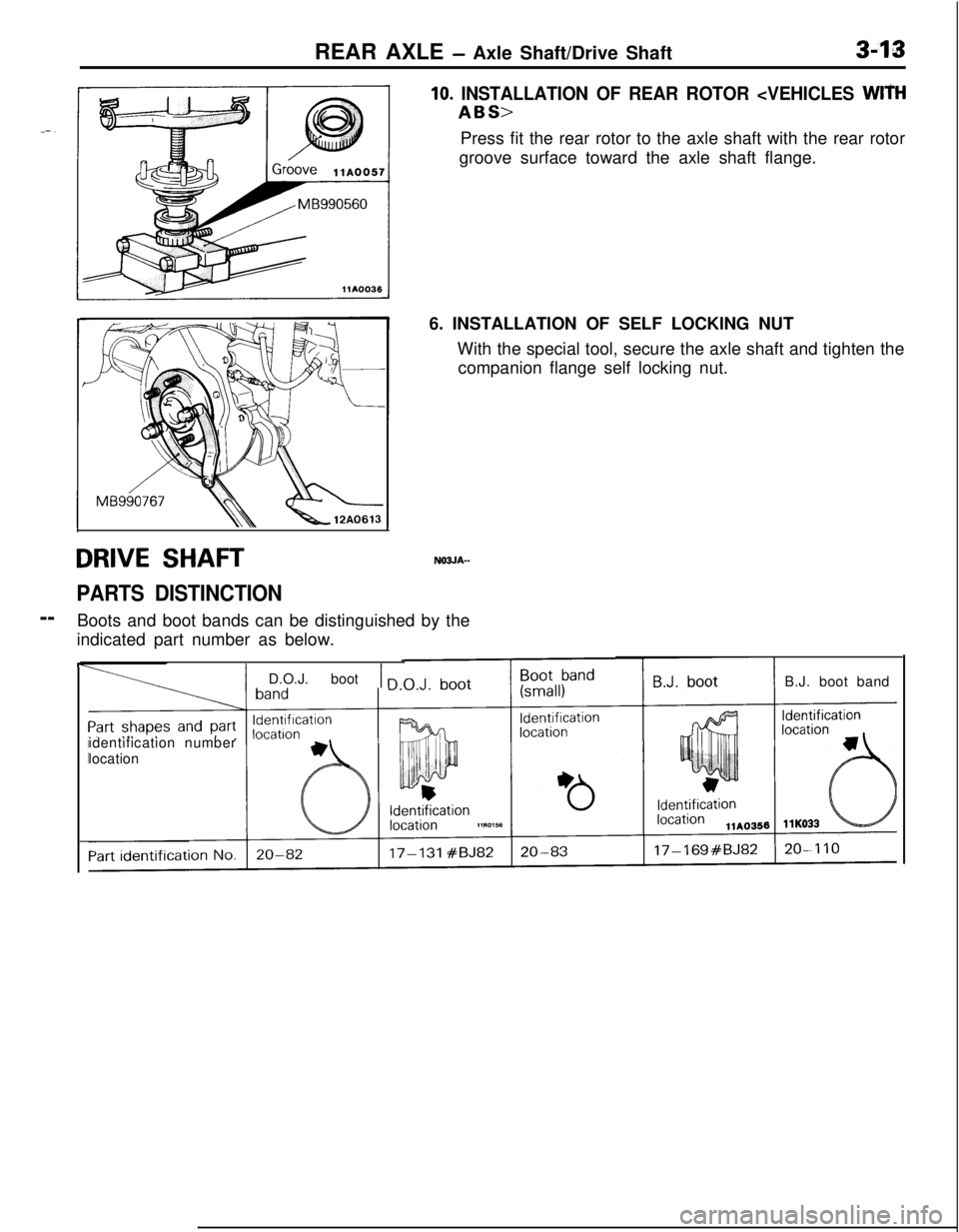
PARTS DISTINCTION--
Boots and boot bands can be distinguished by the
indicated part number as below.
10. INSTALLATION OF REAR ROTOR
groove surface toward the axle shaft flange.
6. INSTALLATION OF SELF LOCKING NUT
With the special tool, secure the axle shaft and tighten the
companion flange self locking nut.
F
I
IIidentification number
location
1 D.O.J. boot 1 nB.J. boot band
Page 120 of 1216
3-18REAR AXLE - Drive Shaft
ring
\
Inner race
1180116
llE507
7.(4) Secure the B.J. boot with boot bands (A) and
(C) to the
drive shaft and B.J.
Caution
-Ensure that the B.J. is at a zero angle with the drive
shaft to ensure the boot contains the specified
amount of air.
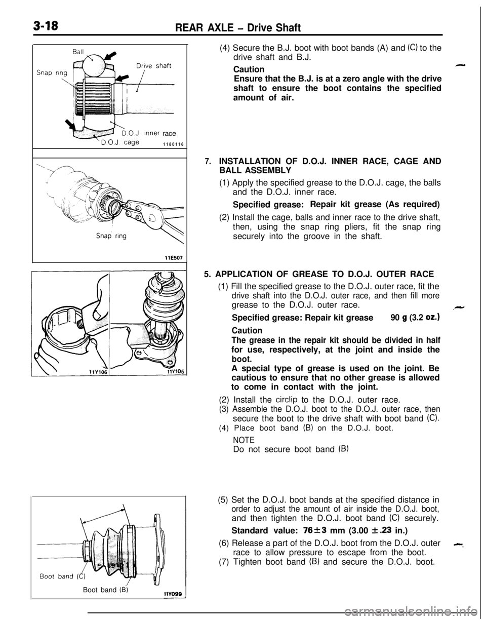
INSTALLATION OF D.O.J. INNER RACE, CAGE AND
BALL ASSEMBLY
(1) Apply the specified grease to the D.O.J. cage, the balls
and the D.O.J. inner race.
Specified grease:Repair kit grease (As required)
(2) Install the cage, balls and inner race to the drive shaft,
then, using the snap ring pliers, fit the snap ring
securely into the groove in the shaft.
5. APPLICATION OF GREASE TO D.O.J. OUTER RACE
(1) Fill the specified grease to the D.O.J. outer race, fit the
drive shaft into the D.O.J. outer race, and then fill moregrease to the D.O.J. outer race.
Specified grease: Repair kit grease
90 g (3.2 oz.)
Caution
The grease in the repair kit should be divided in halffor use, respectively, at the joint and inside the
boot.A special type of grease is used on the joint. Be
cautious to ensure that no other grease is allowed
to come in contact with the joint.
(2) Install the
circlip to the D.O.J. outer race.
(3) Assemble the D.O.J. boot to the D.O.J. outer race, thensecure the boot to the drive shaft with boot band
(C).(4) Place boot band
(B) on the D.O.J. boot.
NOTEDo not secure boot band
(9)(5) Set the D.O.J. boot bands at the specified distance in
order to adjust the amount of air inside the D.O.J. boot,and then tighten the D.O.J. boot band
(C) securely.
Standard value: 76+-3 mm (3.00
& .23 in.)
(6) Release a part of the D.O.J. boot from the D.O.J. outer
--race to allow pressure to escape from the boot.
(7) Tighten boot band
(9) and secure the D.O.J. boot.
Boot band
(8’)
Page 136 of 1216
3-34REAR AXLE - Differential Carrier (Limited Slip Differential)
DIFFERENTIAL CARRIER (LIMITED SLIP DIFFERENTIAL)
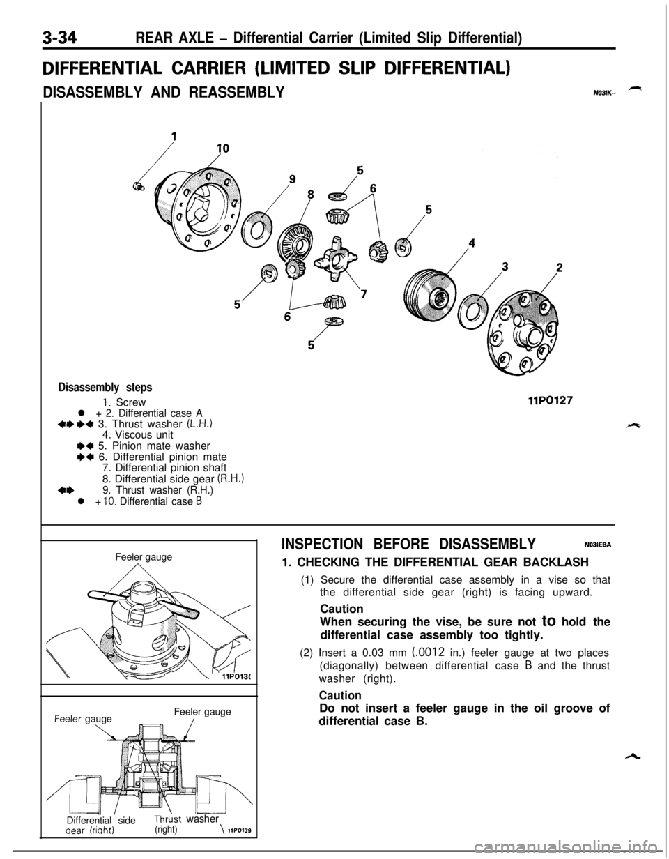
DISASSEMBLY AND REASSEMBLYNO31K--
Disassembly steps
1. Screwl + 2. Differential case A+e I)+ 3. Thrust washer (L.H.)4. Viscous unit
llP0127
I)+ 5. Pinion mate washer
M 6. Differential pinion mate
7. Differential pinion shaft
8. Differential side gear
(R.H.)
4+9. Thrust washer (R.H.)
l +
10. Differential case 6Feeler gauge-eeler gauge
\Feeler gauge/
’ IL4l\’IIDifferential sideThrkt washer
aear (riaht)(right)\llPO139
INSPECTION BEFORE DISASSEMBLYNO3IEBA1. CHECKING THE DIFFERENTIAL GEAR BACKLASH
(1) Secure the differential case assembly in a vise so that
the differential side gear (right) is facing upward.
Caution
When securing the vise, be sure not to hold the
differential case assembly too tightly.
(2) Insert a 0.03 mm (.0012 in.) feeler gauge at two places
(diagonally) between differential case
B and the thrust
washer (right).
CautionDo not insert a feeler gauge in the oil groove of
differential case B.
Page 138 of 1216
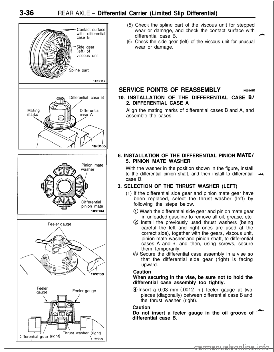
3-36REAR AXLE - Differential Carrier (Limited Slip Differential)Contact surface
with differential
viscous unit
llPO142
Mamaifferential case
BPinion mate
washer
bDifierential7-pinion matellPO134Feeler gauge
Feeler
gaugeFeeler gauge
lifferential gear (right)Thrust washer (right),\llPO130
1(5) Check the
spline part of the viscous unit for stepped
wear or damage, and check the contact surface with
differential case B.
45
(6)Check the side gear (left) of the viscous unit for unusualwear or damage.
SERVICE POINTS OF REASSEMBLYNOOINBE
10. INSTALLATION OF THE DIFFERENTIAL CASE B/2. DIFFERENTIAL CASE A
Align the mating marks of differential cases
B and A, and
assemble the cases.
6. INSTALLATION OF THE DIFFERENTIAL PINION
MATE/5. PINION MATE WASHER
With the washer in the position shown in the figure, install
to the differential pinion shaft, and then install to differentialM.case
B.3. SELECTION OF THE THRUST WASHER (LEFT)
(1) If the differential side gear and pinion mate gear have
been replaced, select the thrust washer (left) by
following the steps below.
@ Wash the differential side gear and pinion mate gear
in unleaded gasoline to remove all oil, grease, etc.
@ Install the previously used thrust washers (being
careful the left and right ones are used at the
correct side), together with the gears, viscous unit,
pinion mate washer and pinion shaft, to differential
cases A and
B, and then, using screws, secure
them temporarily.
@ Secure the differential case assembly in a vise so
that the differential side gear (right) is facing
upward.Caution
When securing in the vise, be sure not to hold the
differential case assembly too tightly.
@I Insert a 0.03 mm LOO12 in.) feeler gauge at two
places (diagonally) between differential case
B and
the thrust washer (right).
CautionDo not insert a feeler gauge in the oil groove of
rsrdifferential case B.
Page 149 of 1216
BRAKES - Anti-lock Braking System Troubleshooting5-9
ANTI-LOCK BRAKING SYSTEM
-- TROUBLESHOOTINGNO!JEBAE
PARTICULAR CHARACTERISTICS OF
THE ANTI-LOCK BRAKING SYSTEMModels equipped with the anti-lock braking system
(A.B.S.) may exhibit one or more of the following
characteristics from time to time, but none of these
is abnormal.
(1) A pulsing feeling in the brake pedal, or vibration
of the body or the steering wheel, when the
anti-lock braking system is activated by sudden
braking or by braking on a slippery road surface.Actually, this phenomenon is an indication that
the anti-lock braking system is functioning nor-
mally.(2) When the vehicle speed reaches approximately
6 km/h (4 mph) after the engine is started and
the vehicle starts off (for the first time), a
whining motor noise may be heard from the
engine compartment if the vehicle is traveling in
a quiet place, but this noise is simply the result
of a self-check being made of the anti-lock
braking system operation.
TROUBLESHOOTING METHODSProblems related to the anti-lock braking system
(A.B.S.) can be classified into two general categor-
ies: problems in the electrical system and those in
the hydraulic system.For problems in the electrical system, the
self-diagnosis function is built into the electronic control
unit (E.C.U.) causing the A.B.S. warning light to
illuminate as a warning to the driver.
Problems in the hydraulic system (poor braking,
etc.) can be located in the same way as for ordinary
brakes. There is, however, the necessity to check todetermine whether the problem is related to ordin-
ary brake components or to the components relatedto the A.B.S.
HOW TO USE THE TROUBLESHOOTING
FLOW CHART(1) Using the flow chart, check the ABS warning
light light-up sequence and check the condition
of braking operation.
(2) Following the check chart listed in the remedy
column, perform the checks. There are [Explana-tion] and [Hint] in each check chart. Refer to
them when troubleshooting.
NOTEECU: Electronic control unit
HU: Hydraulic unit
MUT: Multi-use tester
Page 150 of 1216
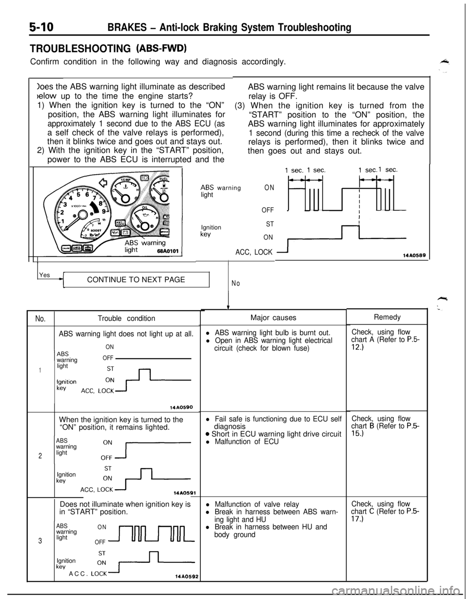
Ioes the ABS warning light illuminate as describedbelow up to the time the engine starts?
1) When the ignition key is turned to the “ON”
position, the ABS warning light illuminates for
approximately 1 second due to the ABS ECU (asa self check of the valve relays is performed),
then it blinks twice and goes out and stays out.
2) With the ignition key in the “START” position,
power to the ABS ECU is interrupted and the
5-10BRAKES - Anti-lock Braking System Troubleshooting
TROUBLESHOOTING (ABS-FWD)Confirm condition in the following way and diagnosis accordingly.
ABS warning light remains lit because the valve
relay is OFF.
(3) When the ignition key is turned from the
“START” position to the “ON” position, the
ABS warning light illuminates for approximately
1 second (during this time a recheck of the valverelays is performed), then it blinks twice and
then goes out and stays out.
ABS warning
lightON
OFF
1Ignition
kev
ST
ON
ACC, LOCK
IYes
CONTINUE TO NEXT PAGE
No
No.Trouble condition
ABS warning light does not light up at all.
ON
1 --ABSwarningOFF
1lightlgnitlon
kev
14A0590When the ignition key is turned to the
“ON” position, it remains lighted.
ABSwarning
2light
Ignition
kevACC,
LO:+14AOSQlDoes not illuminate when ignition key is
in “START” position.
ABSONwarning
3lightOFFUULkev ACC.
LO:-+-Ignition14A0592
1 sec. 1 sec.1 sec.1 sec.
---
IIII
3114AO589
IMajor causes
l ABS warning light bulb is burnt out.Check, using flow
l Open in ABS warning light electricalchart A (Refer to P.5-
circuit (check for blown fuse)12.)
l Fail safe is functioning due to ECU selfdiagnosis
o Short in ECU warning light drive circuitl Malfunction of ECU
l Malfunction of valve relayl Break in harness between ABS warn-
ing light and HU
l Break in harness between HU and
body groundRemedy
Check, using flow
chart
B (Refer to P.5-
15.)
Check, using flow
chart C (Refer to P.5-17.)
Page 151 of 1216
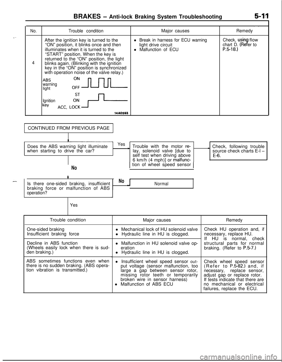
BRAKES - Anti-lock Braking System Troubleshooting5-14
./
No.Trouble conditionMajor causesRemedyAfter the ignition key is turned to the
l Break in harness for ECU warningCheck, usinflow
“ON” position, it blinks once and then
light drive circuit
chart D. (Re er to9illuminates when it is turned to the
l Malfunction of ECUP.5-18.)“START” position. When the key is
4returned to the “ON” position, the light
blinks again. (Blinking with the ignition
key in the “ON” position is synchronized
with operation noise of the valve relay.)
ABSwarninglighto:-
Ignition
keyACC. LCi+-
14*0593CONTINUED FROM PREVIOUS PAGE
Does the ABS warning light illuminate
when starting to drive the car?
Yes~ Trouble with the motor re-lay, solenoid valve [due toL Check, following trouble
source check charts E-l -self test when driving above
E-6.6 km/h (4 mph)] or malfunc-
NoIs there one-sided braking, insufficient
braking force or malfunction of ABS
operation?
YesTrouble condition
Major causes
One-sided braking
Insufficient braking forcel Mechanical lock of HU solenoid valve
l Hydraulic line in HU is clogged.
Decline in ABS function
(Wheels easily lock when there is sud-
den braking.)
ABS sometimes functions even when
there is no sudden braking. (ABS opera-
tion vibration is transmitted.)
1 tion of wheel speed sensor 1
NoNormall Malfunction in HU solenoid valve op-
erationl Hydraulic line in HU is clogged.
l Insufficient wheel speed sensor out-
put voltage (sensor malfunction, too
large a gap between sensor rotor,
missing rotor teeth or temporarily
broken wire in sensor harness)
l Malfunction of ABS ECU
RemedyCheck HU operation and, if
necessary, replace HU.
If HU is normal, check
structural parts for normal
braking. (Refer to
P.5-7.)Check wheel speed sensor
(Refer to
P.5-82.) and, ifnecessary,replace sensor,
adjust gap or replace rotor.
If tests indicate that there are
no mechanical or electrical
failures, replace the ECU.
Page 152 of 1216
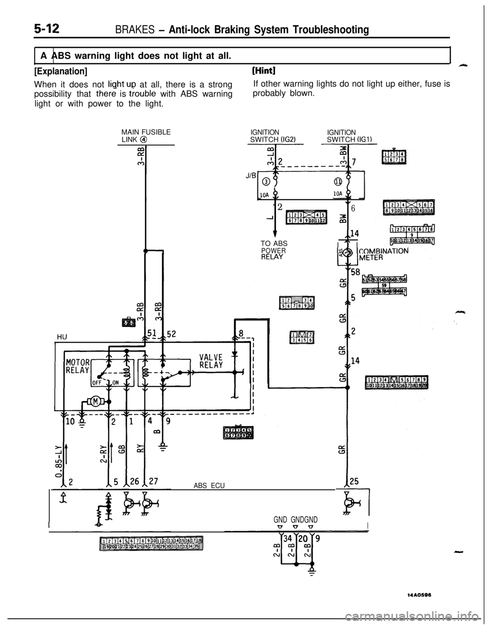
possibility that there is trouble with ABS warning
light or with power to the light.probably blown.
MAIN FUSIBLE
LINK @
5-12BRAKES - Anti-lock Braking System TroubleshootingA ABS warning light does not light at all.
I_
[Explanation][Hint]When it does not
liuht ULI at all, there is a strongIf other warning lights do not light up either, fuse is
IGNITIONSWITCH (IG2)IGNITIONSWITCH (IGl)
10A +,
“2.I6
-1z
v,,14TO ABS
I
” IPOWERIs&h ICOMBINAT~~N
ABS ECU
IGND GNDGNDv v vI
-14AO596