ECU MITSUBISHI ECLIPSE 1991 Service Manual
[x] Cancel search | Manufacturer: MITSUBISHI, Model Year: 1991, Model line: ECLIPSE, Model: MITSUBISHI ECLIPSE 1991Pages: 1216, PDF Size: 67.42 MB
Page 2 of 1216
2INTRODUCTION AND MASTER TROUBLESHOOTING - How to Use This Manual
HOW TO USE THIS MANUALNOaM
CONTENTSThe preceding page contains GROUP INDEX which
lists the group title and group number.
PAGE NUMBERS
All page numbers consist of two sets of digits
separated by a dash. The digits preceding the dash
identify the
number of the group. The digits follow-
ing the dash represent the consecutive page num-
ber within the group. The page numbers can be
found on the top left or right of each page.
TEXT
Unless otherwise specified, each service procedurecovers all models. Procedures covering specific
models are identified by the model codes, or similar
designation (engine type, transaxle type, etc.). A
description of these designations is covered in this
unit under “VEHICLE IDENTIFICATION”.
TROUBLESHOOTING
Troubleshootings are classified into master trouble-
shooting and group troubleshooting and located as
follows:
The master troubleshooting is prepared when the
trouble symptom relates to two or more groups and
given in MASTER TROUBLESHOOTING.
The group troubleshooting guide is prepared for
causes of problems related to that individual group
only; a troubleshooting guide is prepared for each
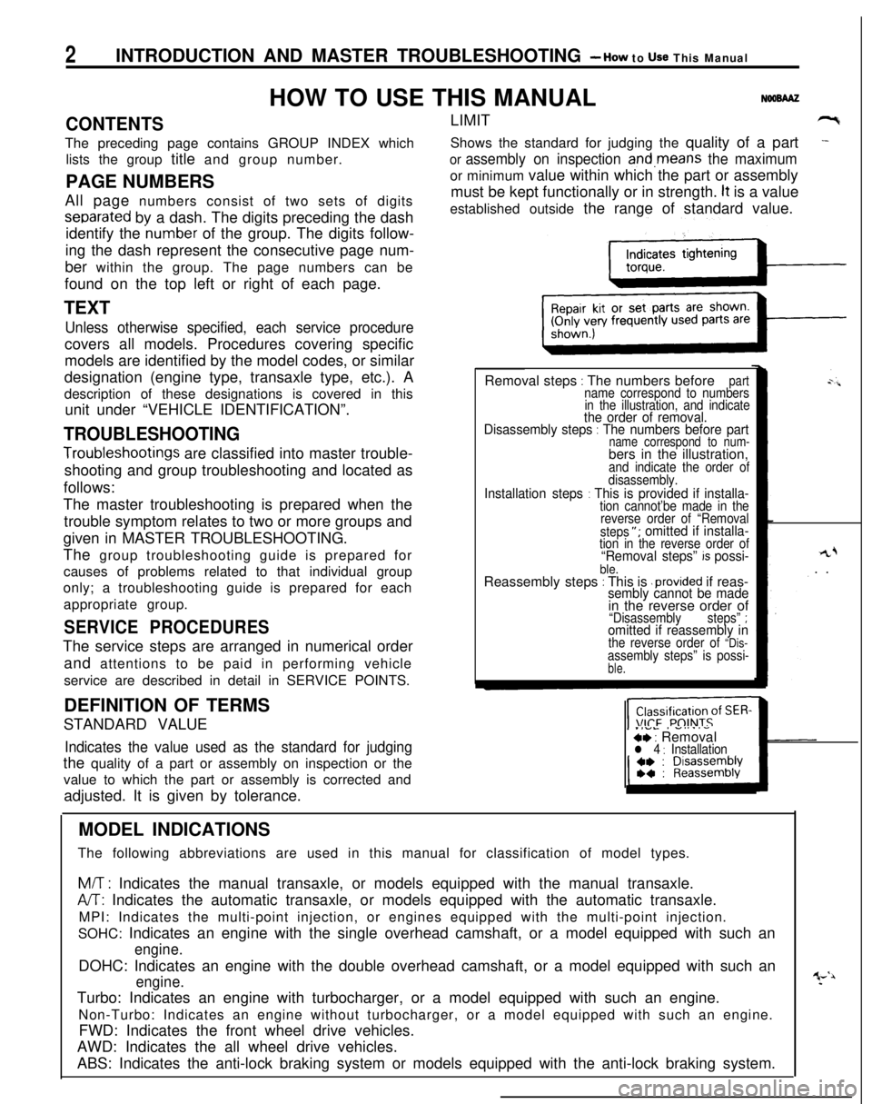
appropriate group.LIMIT
-9Shows the standard for judging the quality of a part
-
or assembly on inspection and,means the maximumor minimum value within which the part or assembly
must be kept functionally or in strength.
It is a value
established outside the range of standard value.
Removal steps
: The numbers beforepartname correspond to numbers
in the illustration, and indicate
the order of removal.
Disassembly steps : The numbers before partname correspond to num-bers in the illustration,
and indicate the order of
disassembly.
Installation steps : This is provided if installa-tion cannot’be made in the
reverse order of “Removal
steps
“; omitted if installa-tion in the reverse order of“Removal steps” k possi-ble.Reassembly steps : This is .provided if reas-sembly cannot be made
rL+. .
in the reverse order of
“Disassemblysteps” ;omitted if reassembly inthe reverse order of “Dis-assembly steps” is possi-ble.
SERVICE PROCEDURESThe service steps are arranged in numerical order
and attentions to be paid in performing vehicle
service are described in detail in SERVICE POINTS.
.IVL, -....-ce : Removall 4 : InstallationDEFINITION OF TERMS
STANDARD VALUEIndicates the value used as the standard for judgingthe quality of a part or assembly on inspection or the
value to which the part or assembly is corrected and
adjusted. It is given by tolerance.
MODEL INDICATIONS
The following abbreviations are used in this manual for classification of model types.
M/T : Indicates the manual transaxle, or models equipped with the manual transaxle.
A/T: Indicates the automatic transaxle, or models equipped with the automatic transaxle.
MPI: Indicates the multi-point injection, or engines equipped with the multi-point injection.
SOHC: Indicates an engine with the single overhead camshaft, or a model equipped with such an
engine.DOHC: Indicates an engine with the double overhead camshaft, or a model equipped with such an
engine.Turbo: Indicates an engine with turbocharger, or a model equipped with such an engine.
Non-Turbo: Indicates an engine without turbocharger, or a model equipped with such an engine.
FWD: Indicates the front wheel drive vehicles.
AWD: Indicates the all wheel drive vehicles.
ABS: Indicates the anti-lock braking system or models equipped with the anti-lock braking system.
Page 15 of 1216
INTRODUCTION AND MASTER TROUBLESHOOTING - Precautions before Set&e15
F16171
Correct
Cl6385
Cl6367
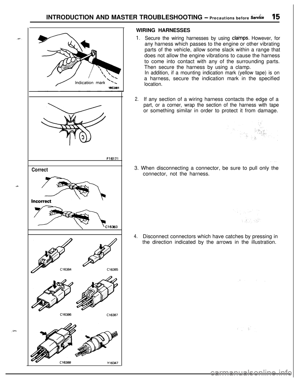
Y16347WIRING HARNESSES
1.Secure the wiring harnesses by using cla’mps. However, forany harness which passes to the engine or other vibrating
parts of the vehicle, allow some slack within a range that
does not allow the engine vibrations to cause the harness
to come into contact with any of the surrounding parts.
Then secure the harness by using a clamp.
In addition, if a mounting indication mark (yellow tape) is ona harness, secure the indication mark in the specified
location.
2.If any section of a wiring harness contacts the edge of a
part, or a corner, wrap the section of the harness with tapeor something similar in order to protect it from damage.
3. When disconnecting a connector, be sure to pull only the
connector, not the harness.
4.Disconnect connectors which have catches by pressing in
the direction indicated by the arrows in the illustration.
Page 17 of 1216
INTRODUCTION AND MASTER TROUBLESHOOTING - Precautions before Sew&e‘37
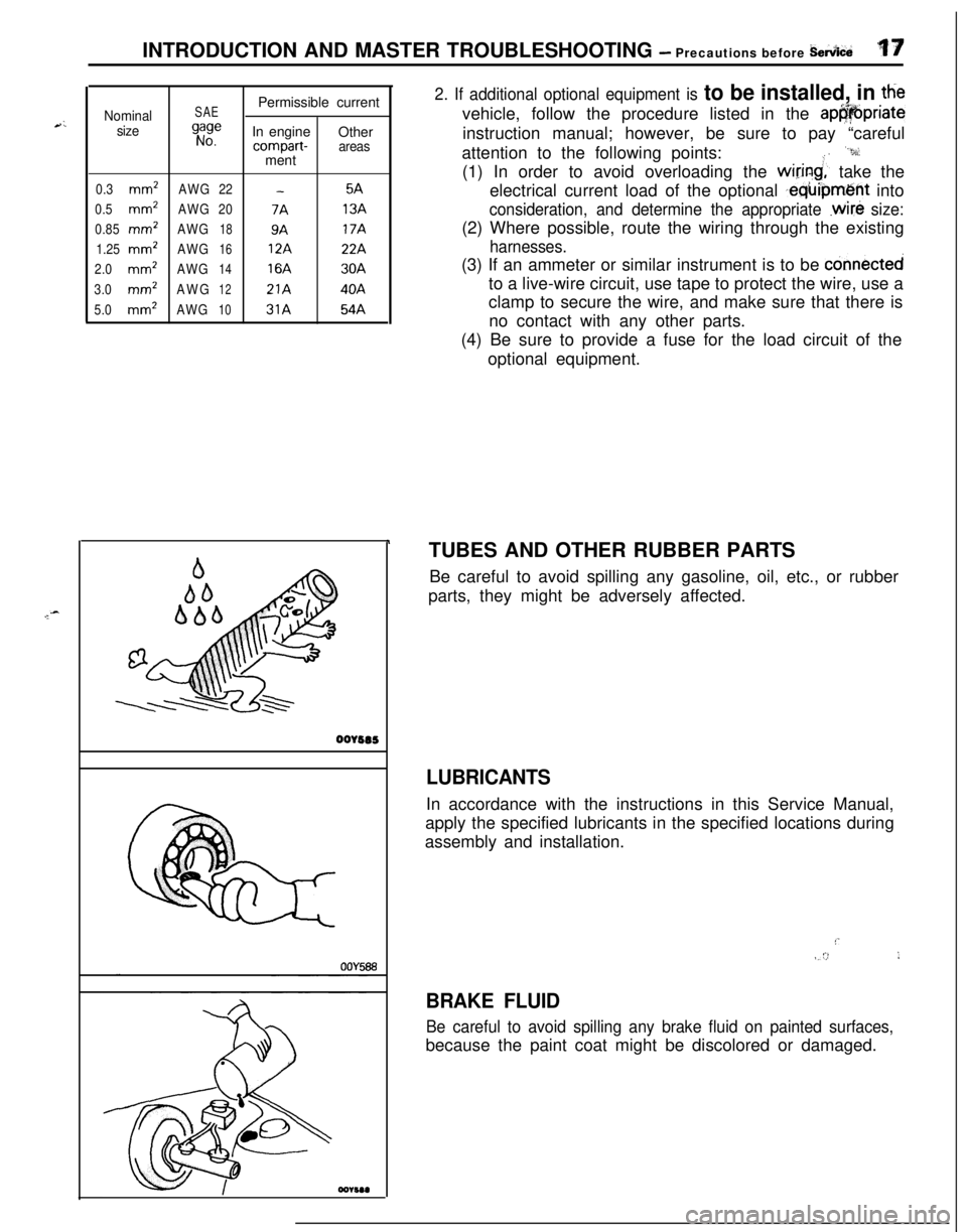
Nominal
sizeSAE
gi:ePermissible current
In engine
Othercompart-areasment
0.3mm2AWG22-5A
0.5
mm2AWG207A13A
0.85
mm’AWG189A17A
1.25
mm2AWG1612A22A
2.0mm2AWG1416A30A
3.0mm’AWG1221A40A
5.0mm2AWG1031A54A
r ‘.
oorsas
2. If additional optional equipment is to be installed, in ttievehicle, follow the procedure listed in the
ap@@priateinstruction manual; however, be sure to pay “careful
attention to the following points:
“9:(1) In order to avoid overloading the
wiring;’ take the
electrical current load of the optional
,equipment into
consideration, and determine the appropriate .wire size:(2) Where possible, route the wiring through the existing
harnesses.(3) If an ammeter or similar instrument is to be
connectedto a live-wire circuit, use tape to protect the wire, use a
clamp to secure the wire, and make sure that there is
no contact with any other parts.
(4) Be sure to provide a fuse for the load circuit of the
optional equipment.
TUBES AND OTHER RUBBER PARTS
Be careful to avoid spilling any gasoline, oil, etc., or rubber
parts, they might be adversely affected.
LUBRICANTSIn accordance with the instructions in this Service Manual,
apply the specified lubricants in the specified locations during
assembly and installation.
!’IV/ :>,I
BRAKE FLUID
Be careful to avoid spilling any brake fluid on painted surfaces,because the paint coat might be discolored or damaged.
Page 19 of 1216
c
--INTRODUCTION AND MASTER
TROUBLESHOOTtNG - Towing and Hoi&gT9
I-
Sling type
Wheel lift type
Flat bed type
iling type
Vheel lift type
lat bed type
TOWING AND HOISTINGNOOGA-
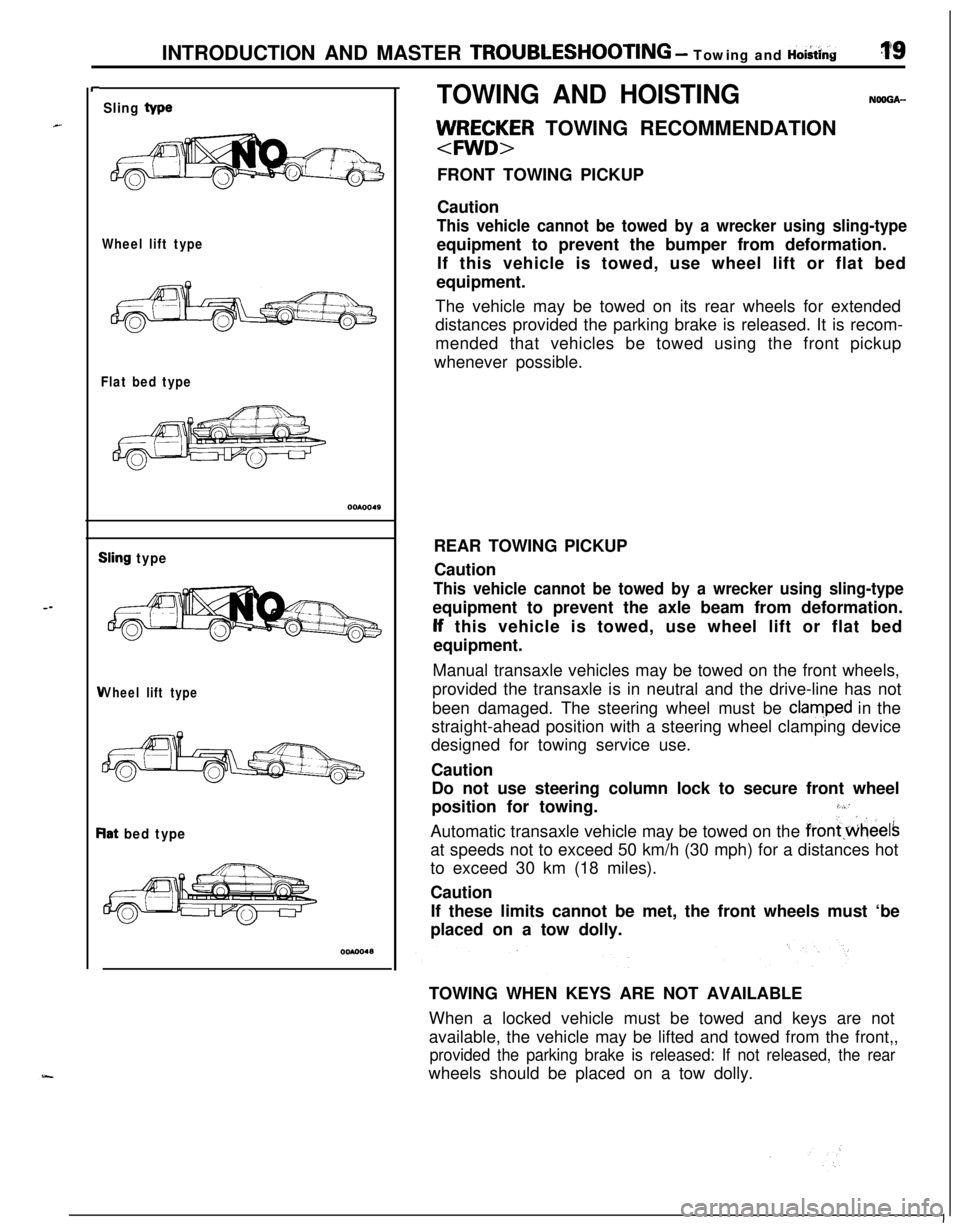
llJ/RE;~R TOWING RECOMMENDATION
FRONT TOWING PICKUP
Caution
This vehicle cannot be towed by a wrecker using sling-typeequipment to prevent the bumper from deformation.
If this vehicle is towed, use wheel lift or flat bed
equipment.
The vehicle may be towed on its rear wheels for extended
distances provided the parking brake is released. It is recom-
mended that vehicles be towed using the front pickup
whenever possible.
REAR TOWING PICKUP
Caution
This vehicle cannot be towed by a wrecker using sling-typeequipment to prevent the axle beam from deformation.lf this vehicle is towed, use wheel lift or flat bed
equipment.
Manual transaxle vehicles may be towed on the front wheels,
provided the transaxle is in neutral and the drive-line has not
been damaged. The steering wheel must be
clam,ped in the
straight-ahead position with a steering wheel clamping device
designed for towing service use.
Caution
Do not use steering column lock to secure front wheel
position for towing.
3,“’Automatic transaxle vehicle may be towed on the
frontwheelsat speeds not to exceed 50 km/h (30 mph) for a distances hot
to exceed 30 km (18 miles).
Caution
If these limits cannot be met, the front wheels must ‘be
placed on a tow dolly.
TOWING WHEN KEYS ARE NOT AVAILABLE
When a locked vehicle must be towed and keys are not
available, the vehicle may be lifted and towed from the front,,
provided the parking brake is released: If not released, the rearwheels should be placed on a tow dolly.
I
Page 20 of 1216
20INTRODUCTION AND MASTER TROUBLESHOOTING - Towing and Hoisting
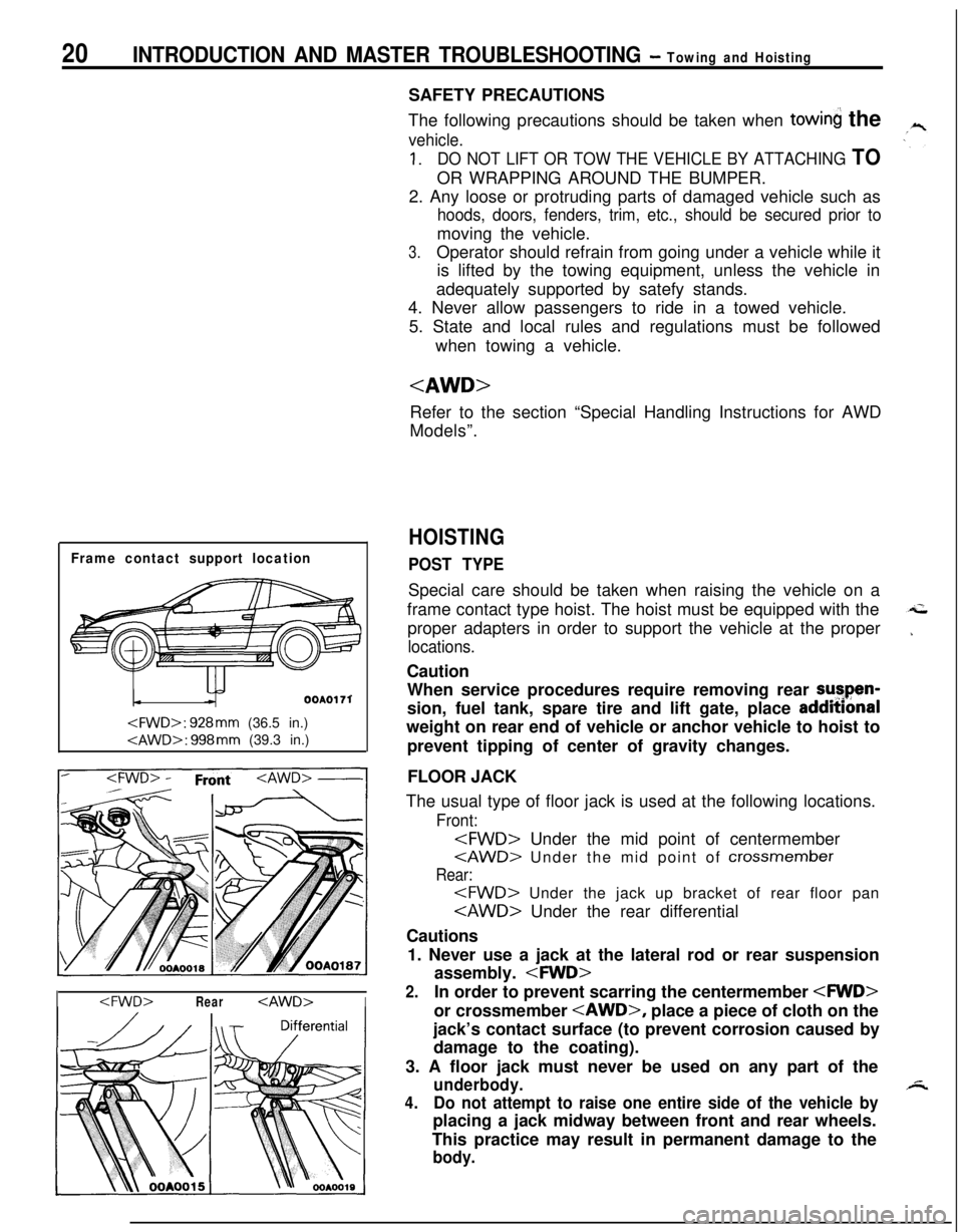
Frame contact support location
OOAOI 71
I
The following precautions should be taken when
towin the
vehicle.
1.DO NOT LIFT OR TOW THE VEHICLE BY ATTACHING TOOR WRAPPING AROUND THE BUMPER.
2. Any loose or protruding parts of damaged vehicle such as
hoods, doors, fenders, trim, etc., should be secured prior tomoving the vehicle.
3.Operator should refrain from going under a vehicle while it
is lifted by the towing equipment, unless the vehicle in
adequately supported by satefy stands.
4. Never allow passengers to ride in a towed vehicle.
5. State and local rules and regulations must be followed
when towing a vehicle.
Refer to the section “Special Handling Instructions for AWD
Models”.
HOISTING
POST TYPESpecial care should be taken when raising the vehicle on a
frame contact type hoist. The hoist must be equipped with the
proper adapters in order to support the vehicle at the proper
locations.Caution
When service procedures require removing rear sutpen-
sion, fuel tank, spare tire and lift gate, place addmonal
weight on rear end of vehicle or anchor vehicle to hoist to
prevent tipping of center of gravity changes.
FLOOR JACK
The usual type of floor jack is used at the following locations.
Front:
Rear:
Cautions
1. Never use a jack at the lateral rod or rear suspension
assembly.
2.In order to prevent scarring the centermember
jack’s contact surface (to prevent corrosion caused by
damage to the coating).
3. A floor jack must never be used on any part of the
underbody.
4.Do not attempt to raise one entire side of the vehicle byplacing a jack midway between front and rear wheels.
This practice may result in permanent damage to the
body.
Page 23 of 1216
Special Handling lnstruction~INTRODUCTION AND MASTER TROUBLESHOOTING - for AWD Models23
7T
TFree roller
00P0030
T&a
TAxle standOOPOO37
Front tie-down bracket
16PO209
14A0198
OOPO036
SPEEDOMETER TESTIF A FREE ROLLER IS USED
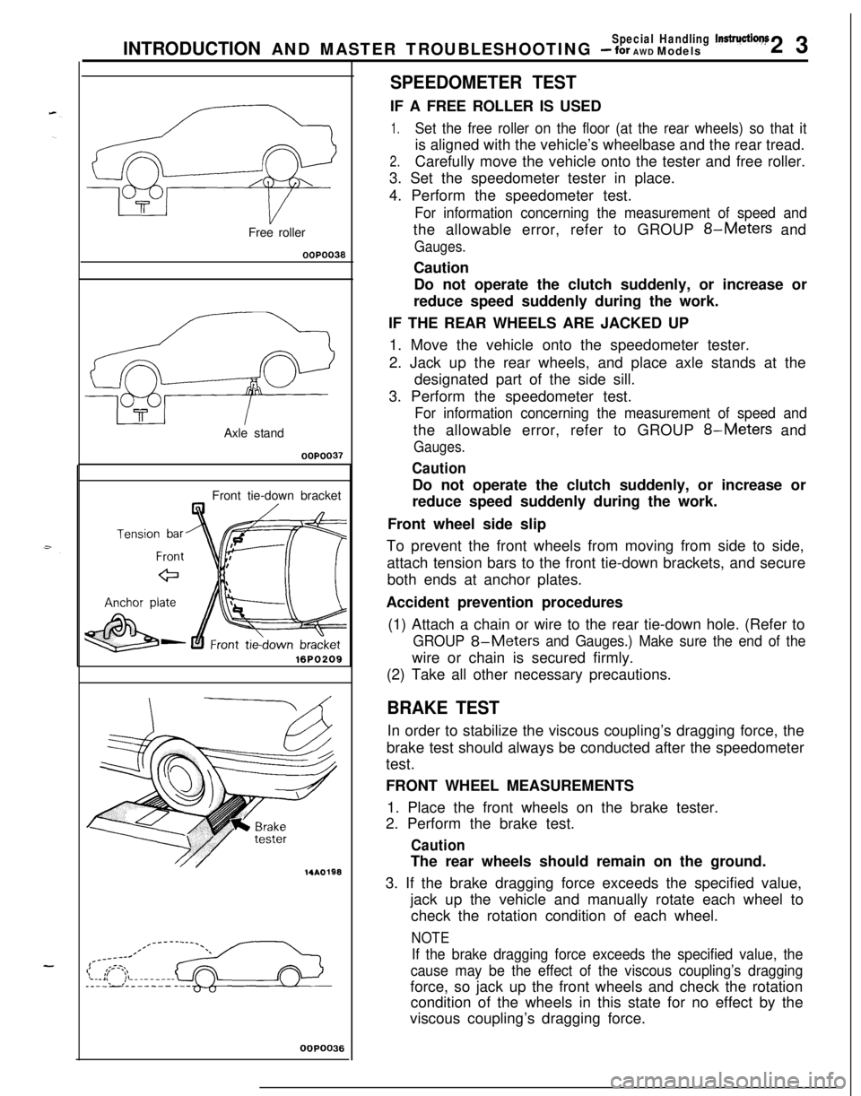
1.Set the free roller on the floor (at the rear wheels) so that itis aligned with the vehicle’s wheelbase and the rear tread.
2.Carefully move the vehicle onto the tester and free roller.
3. Set the speedometer tester in place.
4. Perform the speedometer test.
For information concerning the measurement of speed andthe allowable error, refer to GROUP
8-Meters and
Gauges.Caution
Do not operate the clutch suddenly, or increase or
reduce speed suddenly during the work.
IF THE REAR WHEELS ARE JACKED UP
1. Move the vehicle onto the speedometer tester.
2. Jack up the rear wheels, and place axle stands at the
designated part of the side sill.
3. Perform the speedometer test.
For information concerning the measurement of speed andthe allowable error, refer to GROUP
8-Meters and
Gauges.
CautionDo not operate the clutch suddenly, or increase or
reduce speed suddenly during the work.
Front wheel side slip
To prevent the front wheels from moving from side to side,
attach tension bars to the front tie-down brackets, and secure
both ends at anchor plates.
Accident prevention procedures
(1) Attach a chain or wire to the rear tie-down hole. (Refer to
GROUP 8-Meters and Gauges.) Make sure the end of thewire or chain is secured firmly.
(2) Take all other necessary precautions.
BRAKE TESTIn order to stabilize the viscous coupling’s dragging force, the
brake test should always be conducted after the speedometer
test.
FRONT WHEEL MEASUREMENTS
1. Place the front wheels on the brake tester.
2. Perform the brake test.
CautionThe rear wheels should remain on the ground.
3. If the brake dragging force exceeds the specified value,
jack up the vehicle and manually rotate each wheel to
check the rotation condition of each wheel.
NOTE
If the brake dragging force exceeds the specified value, the
cause may be the effect of the viscous coupling’s draggingforce, so jack up the front wheels and check the rotation
condition of the wheels in this state for no effect by the
viscous coupling’s dragging force.
Page 32 of 1216
32INTRODUCTION AND MASTER TROUBLESHOOTING - Master Troubleshooting
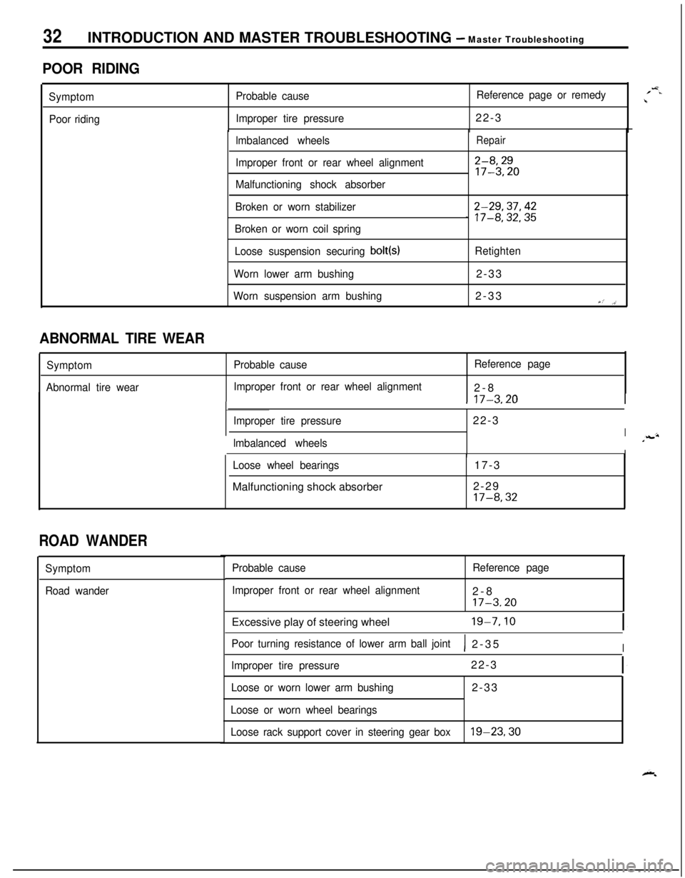
POOR RIDING
Symptom
Poor ridingProbable causeReference page or remedy
Improper tire pressure22-3
lmbalanced wheels
Improper front or rear wheel alignment
Malfunctioning shock absorberRepair
2-8,2917-3.20
Broken or worn stabilizer
Broken or worn coil spring2-29,37,42_ 17-8,32,35
Loose suspension securing bolt(s)Retighten
Worn lower arm bushing2-33
Worn suspension arm bushing2-33Y,’ ,>’
1 17-3.20I
ABNORMAL TIRE WEAR
Symptom
Abnormal tire wearProbable causeReference page
Improper front or rear wheel alignment2-8
Improper tire pressure22-3
Ilmbalanced wheelsIILoose wheel bearingsMalfunctioning shock absorber17-3
2-29
17-8,32
ROAD WANDER
Symptom
Road wanderProbable cause
Improper front or rear wheel alignmentReference page2-8
17-3.20Excessive play of steering wheel
19-7.10
Poor turning resistance of lower arm ball joint1 2-35I
Improper tire pressure22-3
Loose or worn lower arm bushing2-33
Loose or worn wheel bearings
Loose rack support cover in steering gear box
19-23,30
/-=..\
Page 46 of 1216
LUBRICATION AND MAINTENANCE - Maintenance Service
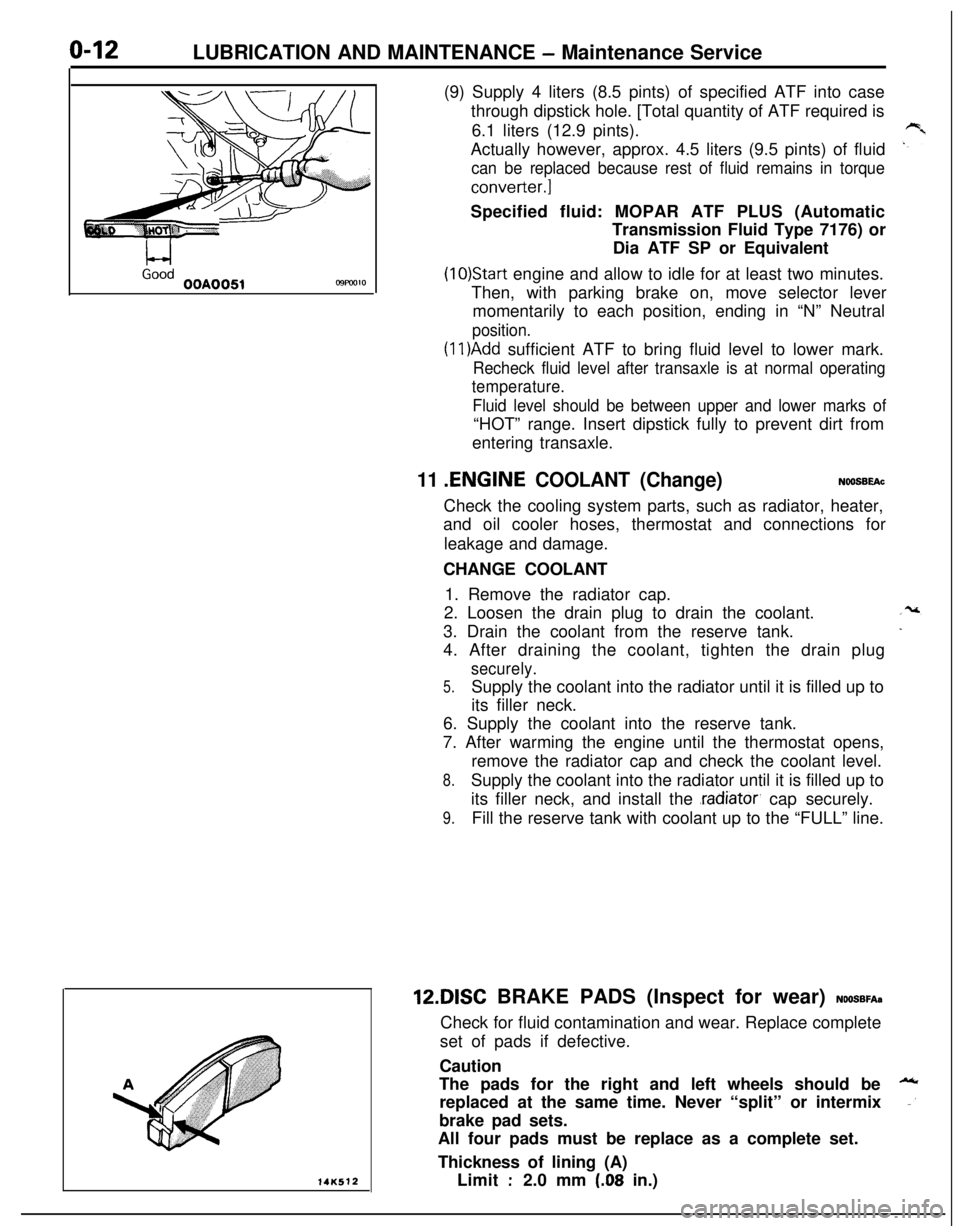
L-4GoodOOA0051C9FW1014K512(9) Supply 4 liters (8.5 pints) of specified ATF into case
through dipstick hole. [Total quantity of ATF required is
6.1 liters (12.9 pints).
Actually however, approx. 4.5 liters (9.5 pints) of fluid
can be replaced because rest of fluid remains in torque
converter.]Specified fluid: MOPAR ATF PLUS (Automatic
Transmission Fluid Type 7176) or
Dia ATF SP or Equivalent
(10)Start engine and allow to idle for at least two minutes.
Then, with parking brake on, move selector lever
momentarily to each position, ending in “N” Neutral
position.
(1 l)Add sufficient ATF to bring fluid level to lower mark.
Recheck fluid level after transaxle is at normal operating
temperature.
Fluid level should be between upper and lower marks of“HOT” range. Insert dipstick fully to prevent dirt from
entering transaxle.
11 .ENGINE COOLANT (Change)NOOSBEAcCheck the cooling system parts, such as radiator, heater,
and oil cooler hoses, thermostat and connections for
leakage and damage.
CHANGE COOLANT
1. Remove the radiator cap.
2. Loosen the drain plug to drain the coolant.
3. Drain the coolant from the reserve tank.
4. After draining the coolant, tighten the drain plug
securely.
5.Supply the coolant into the radiator until it is filled up to
its filler neck.
6. Supply the coolant into the reserve tank.
7. After warming the engine until the thermostat opens,
remove the radiator cap and check the coolant level.
8.Supply the coolant into the radiator until it is filled up to
its filler neck, and install the
.radiator, cap securely.
9.Fill the reserve tank with coolant up to the “FULL” line.12DISC BRAKE PADS (Inspect for wear)
NOOSBFA~Check for fluid contamination and wear. Replace complete
set of pads if defective.
Caution
The pads for the right and left wheels should be
replaced at the same time. Never “split” or intermix
brake pad sets.
All four pads must be replace as a complete set.
Thickness of lining (A)
Limit
:2.0 mm (.08 in.)
Page 56 of 1216
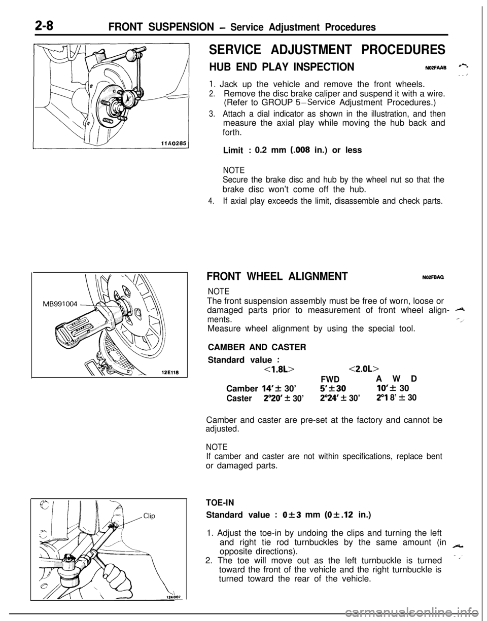
2-8FRONT SUSPENSION - Service Adjustment Procedures
SERVICE ADJUSTMENT PROCEDURES
HUB END PLAY INSPECTIONNO2FAAB --- ’
1. Jack up the vehicle and remove the front wheels.
2.Remove the disc brake caliper and suspend it with a wire.
(Refer to GROUP
5-Service Adjustment Procedures.)
3.Attach a dial indicator as shown in the illustration, and thenmeasure the axial play while moving the hub back and
forth.Limit
: 0.2 mm (.008 in.) or less
NOTE
Secure the brake disc and hub by the wheel nut so that thebrake disc won’t come off the hub.
4.If axial play exceeds the limit, disassemble and check parts.
FRONT WHEEL ALIGNMENTNOZFBAQ
NOTEThe front suspension assembly must be free of worn, loose or
damaged parts prior to measurement of front wheel align-
A
ments.--l
Measure wheel alignment by using the special tool.
CAMBER AND CASTER
Standard value
:
<1.8L><2.0L>
FWDAWD
Camber
14’+ 30’5’k3010’f 30
Caster250 + 30’2”24’ + 30’29 8’ f 30Camber and caster are pre-set at the factory and cannot be
adjusted.
NOTE
If camber and caster are not within specifications, replace bentor damaged parts.
TOE-INStandard value
:Of3 mm (Of.12 in.)
1. Adjust the toe-in by undoing the clips and turning the left
and right tie rod turnbuckles by the same amount (in
-opposite directions).
2. The toe will move out as the left turnbuckle is turned
- ,’toward the front of the vehicle and the right turnbuckle is
turned toward the rear of the vehicle.
Page 59 of 1216
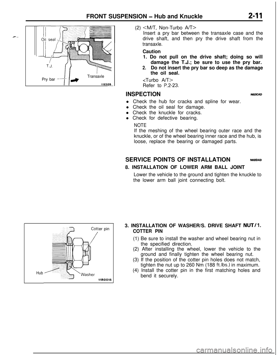
FRONT SUSPENSION - Hub and Knuckle2-11Pry bar
Transaxle
llE5&
Huber pin(2)
Insert a pry bar between the transaxle case and the
drive shaft, and then pry the drive shaft from the
transaxle.Caution
1. Do not pull on the drive shaft; doing so will
damage the T.J.; be sure to use the pry bar.
2.Do not insert the pry bar so deep as the damage
the oil seal.
P.2-23.
INSPECTIONNO2lCADl Check the hub for cracks and spline for wear.
l Check the oil seal for damage.
l Check the knuckle for cracks.
l Check for defective bearing.
NOTEIf the meshing of the wheel bearing outer race and the
knuckle, or of the wheel bearing inner race and the hub, is
loose, replace the bearing or damaged parts.
SERVICE POINTS OF INSTALLATION
NOZIDAD8. INSTALLATION OF LOWER ARM BALL JOINT
Lower the vehicle to the ground and tighten the knuckle to
the lower arm ball joint connecting bolt.
3. INSTALLATION OF WASHER/S. DRIVE SHAFT
NUT/l.
COTTER PIN(1) Be sure to install the washer and wheel bearing nut in
the specified direction.
(2) After installing the wheel, lower the vehicle to the
ground and finally tighten the wheel bearing nut.
(3) If the position of the cotter pin holes does not match,
tighten the nut up to 260 Nm (188
ftlbs.) in maximum.
(4) Install the cotter pin in the first matching holes and
bend it securely.