battery MITSUBISHI ECLIPSE 1991 User Guide
[x] Cancel search | Manufacturer: MITSUBISHI, Model Year: 1991, Model line: ECLIPSE, Model: MITSUBISHI ECLIPSE 1991Pages: 1216, PDF Size: 67.42 MB
Page 168 of 1216
5-28BRAKES -Anti-lock Braking System Troubleshooting
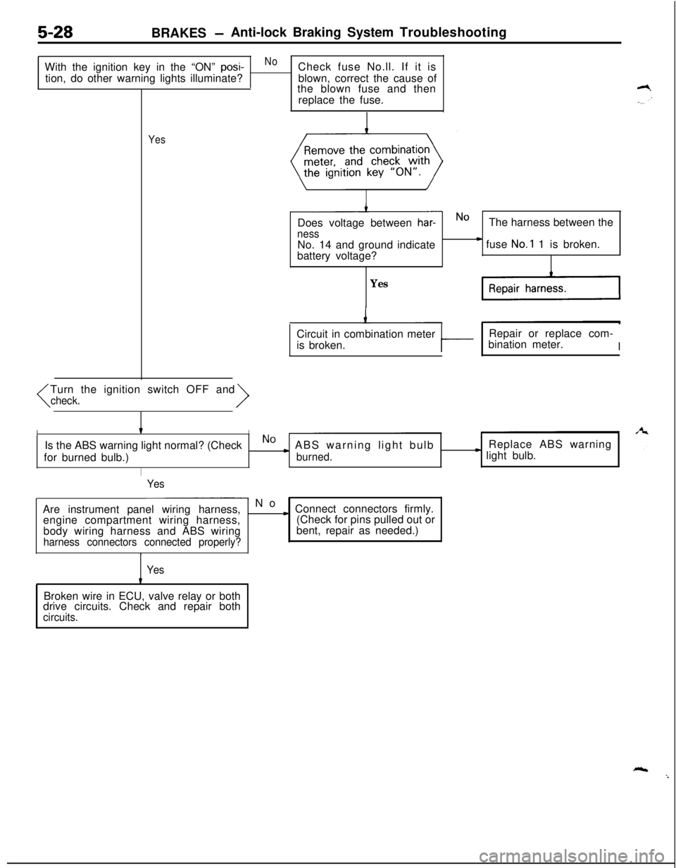
With the ignition key in the “ON”
posi-NoCheck fuse No.ll. If it is
tion, do other warning lights illuminate?blown, correct the cause of
the blown fuse and then
replace the fuse.
YesTurn the ignition switch OFF and
har-NOThe harness between the
nessNo. 14 and ground indicate
battery voltage?) fuse No.1 1 is broken.
YesCircuit in combination meter
is broken.
tRepair or replace com-
bination meter.II
IIIs the ABS warning light normal? (CheckNO) ABS warning light bulbReplace ABS warning
for burned bulb.)
burned.* light bulb.
I
Yes
- No
Are instrument panel wiring harness,
engine compartment wiring harness,
body wiring harness and ABS wiring
harness connectors connected properly?
c Connect connectors firmly.
(Check for pins pulled out or
bent, repair as needed.)
YesBroken wire in ECU, valve relay or both
drive circuits. Check and repair both
circuits.
Page 171 of 1216
BRAKES - Anti-lock Braking System Troubleshooting5-31
SUBIGNITION
%TB(kEzYCH
IODE
;LLF-FIAGNOSIS
CONNECTOR
I Yes1,
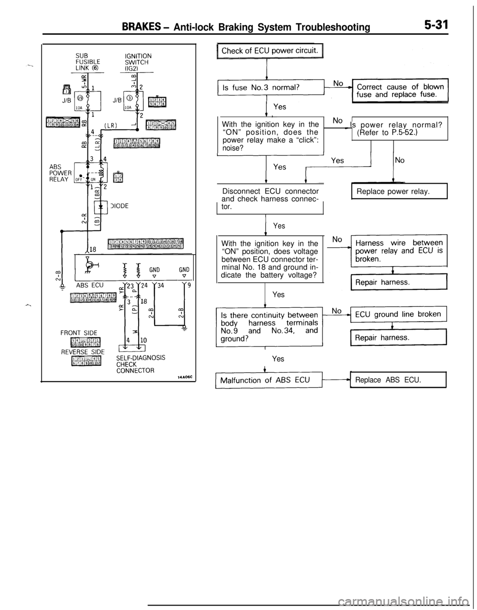
With the ignition key in the
No _ Is power relay normal?
“ON” position, does the
(Refer to P.5-52.)power relay make a “click”:
noise?LDisconnect ECU connector
and check harness connec-Replace power relay.
tor.
YesWith the ignition key in the
“ON” position, does voltage
between ECU connector ter-
minal No. 18 and ground in-
dicate the battery voltage?
Yes
Yes
Replace ABS ECU.
Page 172 of 1216
![MITSUBISHI ECLIPSE 1991 User Guide 5-32BRAKES -Anti-lock Braking System Troubleshooting
CABS warning light does not illuminate when ignition key is in “START” position.
[Explanation]The ABS ECU uses the
IG2 power source which isan MITSUBISHI ECLIPSE 1991 User Guide 5-32BRAKES -Anti-lock Braking System Troubleshooting
CABS warning light does not illuminate when ignition key is in “START” position.
[Explanation]The ABS ECU uses the
IG2 power source which isan](/img/19/57104/w960_57104-171.png)
5-32BRAKES -Anti-lock Braking System Troubleshooting
CABS warning light does not illuminate when ignition key is in “START” position.
[Explanation]The ABS ECU uses the
IG2 power source which isand the ECU turns the valve relay OFF. If the
turned off in the “START” position. The ABSwarning light does not illuminate at this time, there
warning light uses the
IGI power source which isis trouble in the warning light circuit on the valve
not turned off even in the “START” position.relay side.
Consequently, in the “START” position, power is off
MAINIGNITIONFUSIBLESWITCHLINK @I(IGl)J/B
“62
I .1411213141516l7l61911112113114115U6i,79
@COMBINATIONAL METER
“58ABS ECU
1410000
hydraulicunit (HU) connector and
>\/I
1With the ignition key in the
“ON” position, does voltage
between body connector
terminal No.8 and ground
indicate the battery voltage?
Is there continuity between
No~Broken line between HU
body connector terminaland body groundNo.9 and ground?
I
YesIs there continuity between
HU connector terminal No. 8and terminal
No.9?
YesRemove the valve relay. Is
there continuity between
terminal No. 87a and No. 30?
I
Yes1 Replace valve relay.
HU harness malfunction
I
1 Replace HU.
Page 173 of 1216
BRAKES - Anti-lock Braking System Troubleshooting5-33
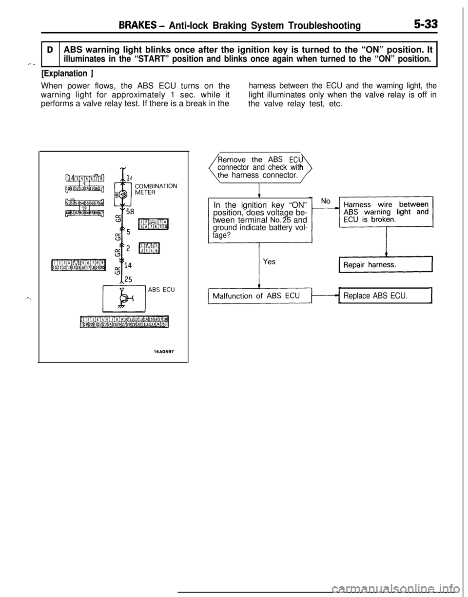
DABS warning light blinks once after the ignition key is turned to the “ON” position. It
illuminates in the “START” position and blinks once again when turned to the “ON” position.*-_
[Explanation ]When power flows, the ABS ECU turns on the
harness between the ECU and the warning light, thewarning light for approximately 1 sec. while itlight illuminates only when the valve relay is off in
performs a valve relay test. If there is a break in the
the valve relay test, etc.
Y
x %l4
9
4
n. 58
ABS ECU
14A0597
EC
4connector and check with
he harness connector. /\/
IIn the ignition key “ON”
position, does voltage be-
tween terminal
No.25 andground indicate battery vol-
tage?
Replace ABS ECU.I
Page 176 of 1216
![MITSUBISHI ECLIPSE 1991 User Guide 5-36BRAKES - Anti-lock Braking System Troubleshooting
E-3Abnormality of G sensor circuit
[Explanation]The ABS ECU turns on the warning light in the
following cases.
lOFF trouble turning G sensor OFF ( MITSUBISHI ECLIPSE 1991 User Guide 5-36BRAKES - Anti-lock Braking System Troubleshooting
E-3Abnormality of G sensor circuit
[Explanation]The ABS ECU turns on the warning light in the
following cases.
lOFF trouble turning G sensor OFF (](/img/19/57104/w960_57104-175.png)
5-36BRAKES - Anti-lock Braking System Troubleshooting
E-3Abnormality of G sensor circuit
[Explanation]The ABS ECU turns on the warning light in the
following cases.
lOFF trouble turning G sensor OFF (It is judged
that the
G sensor continues to be OFF for more
than approximately 13 seconds except when the
lWhen there is a broken wire or short circuit in
the harness for the
G sensor system.
PlUN; F;SIBLEIGNITIONSWITCH (IG2)J/B
G-SENSOR
E-lABSECU
14AO609
Is G sensor normal? (ReferNoto
P.5-86.)Replace G sensor.
I YesWith the ignition key “ON”
_ No m The harness between the
does the voltage betweenG sensor and the ABS
terminal No.6 and groundECU is broken.
indicate battery voltage?
IG sensor circuit is normal.I
Page 177 of 1216
![MITSUBISHI ECLIPSE 1991 User Guide BRAKES - Anti-lock Braking System Troubleshooting5-37
E-4Abnormality of stop light switch circuitI
- [Explanation][Hint]The ABS ECU turns on the warning light in theIf the stop light operates normal, MITSUBISHI ECLIPSE 1991 User Guide BRAKES - Anti-lock Braking System Troubleshooting5-37
E-4Abnormality of stop light switch circuitI
- [Explanation][Hint]The ABS ECU turns on the warning light in theIf the stop light operates normal,](/img/19/57104/w960_57104-176.png)
BRAKES - Anti-lock Braking System Troubleshooting5-37
E-4Abnormality of stop light switch circuitI
- [Explanation][Hint]The ABS ECU turns on the warning light in theIf the stop light operates normal, the ABS harness
following cases.
wire for the stop light switch input circuit to the ECU
lStop light switch may remain on for more thanis broken or there is a malfunction in the ABS ECU.
15 minutes without the ABS functions.
lThe harness wire for the stop light switch may
be open.
AUTO-CRUISE
STOP
--I0.85-G
’LIGHT
w
STOPLIGHTSWITCHABSECURESIS-
TOR
14AO610
Do the stop lights light up _ No c Check the stop light re-and go out normally?lated circuit and repair
problem spots.
Yes
isconnect the ABS ECconnector and inspect at
the harness side
connec-
tor.When the brake pedal is
NoHarness wire between
pressed forcefully, does the
* stop light switch and ABS
voltage between connectorECU is broken.
terminal No. 29 and ground
indicate battery voltage?
c
Repair harness.
Yes.
;gSJ;ght switch circuit is
Page 179 of 1216
![MITSUBISHI ECLIPSE 1991 User Guide BRAKES - Anti-lock Braking System Troubleshooting5-39
E-6Abnormality of valve relay drive circuitI
j-a [Explanation]When the ignition switch is turned ON, the ABSnormal. In addition, normally it monit MITSUBISHI ECLIPSE 1991 User Guide BRAKES - Anti-lock Braking System Troubleshooting5-39
E-6Abnormality of valve relay drive circuitI
j-a [Explanation]When the ignition switch is turned ON, the ABSnormal. In addition, normally it monit](/img/19/57104/w960_57104-178.png)
BRAKES - Anti-lock Braking System Troubleshooting5-39
E-6Abnormality of valve relay drive circuitI
j-a [Explanation]When the ignition switch is turned ON, the ABSnormal. In addition, normally it monitors whether or
ECU switches the valve relay OFF and ON for annot there is power in the valve power monitor line
initial check, compares the voltage of the signal tosince the valve relay is normally ON. Then, if the
the valve relay and valve power monitor line voltagesupply of power to the valve power monitor line is
to check whether the valve relay operation is
interrupted, the warning light illuminates.
IGNITIONMAIN FUSIBLESWITCHLINK @W-31)When the valve relay is
checked, are the followingconditions found?No.85-No.86:resistancevalue 60-120 Q
No.30-No.87a: continuityNo.30-No.87: No continui-
When battery voltage is ap-plied between terminals
No.86 and No. 85 grounded.
No. 30-No. 87: continuity
No.
30-No. 87a: no continui-
tyremove the HU connec-
NoValve relay malfunction
Replace valve relay.
IConnect the HU
remove the ECU con-
I Yes
IValve relay drive circuit isnormal.I
Page 180 of 1216
![MITSUBISHI ECLIPSE 1991 User Guide 5-40BRAKES - Anti-lock Braking System Troubleshooting
E-7Abnormality of motor drive circuit
[Explanation]The ABS ECU illuminates the warning light for the
motor relay and motor in the following cases. MITSUBISHI ECLIPSE 1991 User Guide 5-40BRAKES - Anti-lock Braking System Troubleshooting
E-7Abnormality of motor drive circuit
[Explanation]The ABS ECU illuminates the warning light for the
motor relay and motor in the following cases.](/img/19/57104/w960_57104-179.png)
5-40BRAKES - Anti-lock Braking System Troubleshooting
E-7Abnormality of motor drive circuit
[Explanation]The ABS ECU illuminates the warning light for the
motor relay and motor in the following cases.
l When the motor relay does not function
lWhen there is trouble with the motor itself and it
does not revolve
[Hint]If there is motor operation noise when wheel speed
exceeds
Gkm/h (4mph) when starting up after the
engine is started, there is a broken or short circuitedmotor monitor wire.
lWhen the motor ground line is disconnected andthe motor does not revolve
l When the motor continues to revolve
Does the motor make a
YesBroken wire or short cir-noise when wheel speed
-cuit in motor monitor line
exceeds 6 km/h (4 mph)?
b
NoRepair the harness between HU and ECU.
emove the motor rela
ABS ECU
14A0105
Remove the motor relav and
check resistance values.
No.
85-No. 86:resistancevalue 30-60 QNo.30-No.87: no continui-
ty
Battery voltage is applied on
terminals No. 86 and No. 85
grounded
No. 30-No. 87: continuity
Yes
q Motor relay malfunction 1
Replace motor relay.I
Is pump motor ground con-netted normally?Connect ground wire.I
b
Does voltage between bodyNo
connector terminal 51 andIBroken wire in pumpmotor power circuit
ground indicate battery vol-
tage?1Repair the harness.
YesIs resistance between body
- No L Malfunction of harness
connector terminal No. 2 andbetween HU and ECU
No.26 30-60 ohms?b
YesRepair harness.
Motor drive circuit is normal.
Page 192 of 1216
5-52BRAKES - Service Adjustment Procedures
16LO312lOWOO
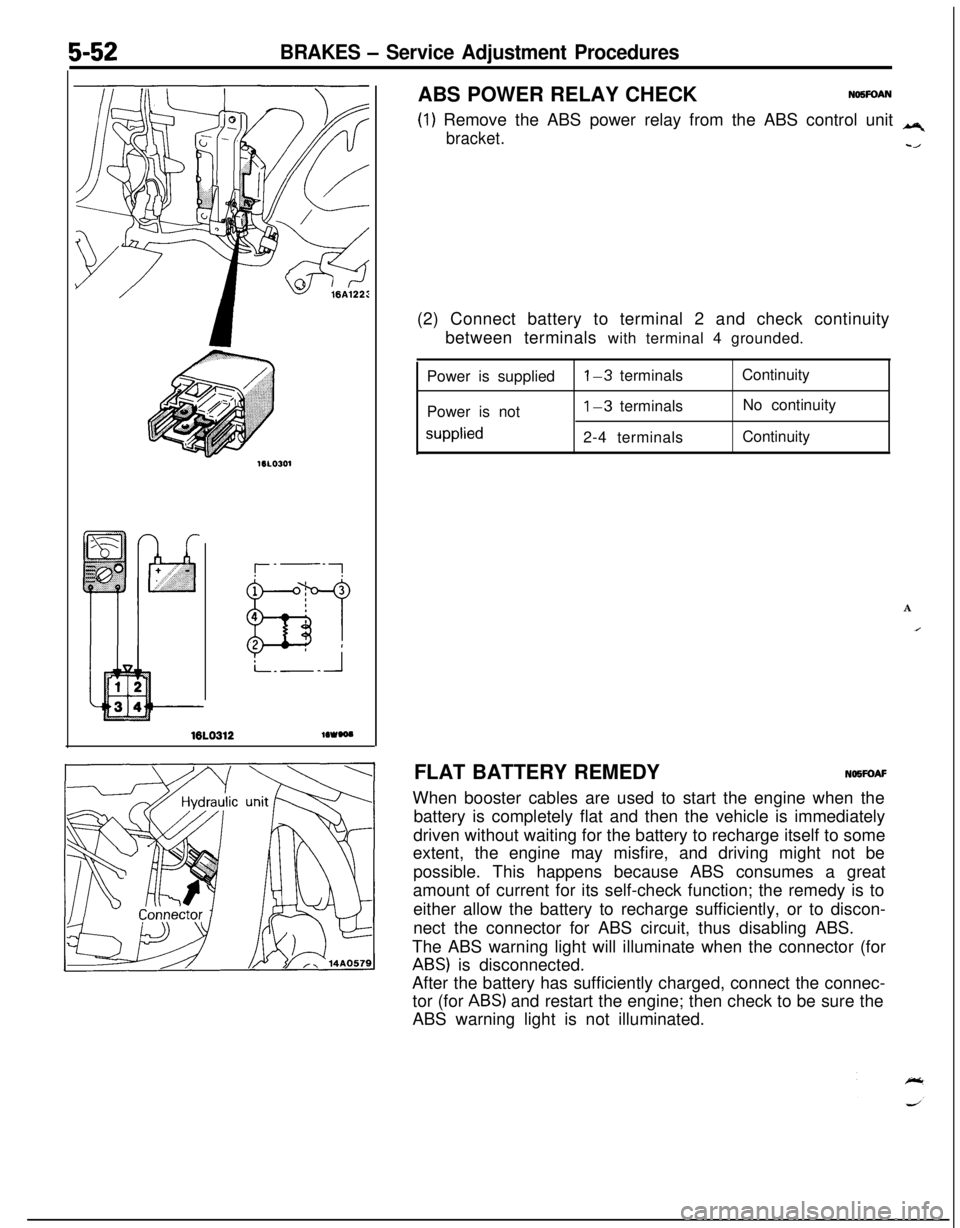
(1) Remove the ABS power relay from the ABS control unit q
bracket.-/ABS POWER RELAY CHECK
NO5FOAN(2) Connect battery to terminal 2 and check continuity
between terminals with terminal 4 grounded.
Power is supplied
Power is not
supplied
l-3 terminals
1-3 terminals
2-4 terminalsContinuity
No continuity
Continuity
A
IFLAT BATTERY REMEDYNOWOAF
When booster cables are used to start the engine when the
battery is completely flat and then the vehicle is immediately
driven without waiting for the battery to recharge itself to some
extent, the engine may misfire, and driving might not be
possible. This happens because ABS consumes a great
amount of current for its self-check function; the remedy is to
either allow the battery to recharge sufficiently, or to discon-
nect the connector for ABS circuit, thus disabling ABS.
The ABS warning light will illuminate when the connector (for
ABS) is disconnected.
After the battery has sufficiently charged, connect the connec-
tor (for
ABS) and restart the engine; then check to be sure the
ABS warning light is not illuminated.
Page 262 of 1216
7-14COOLING - Radiator
A
OFF
ON
h
--- ,
BWatertemperature
16v1100
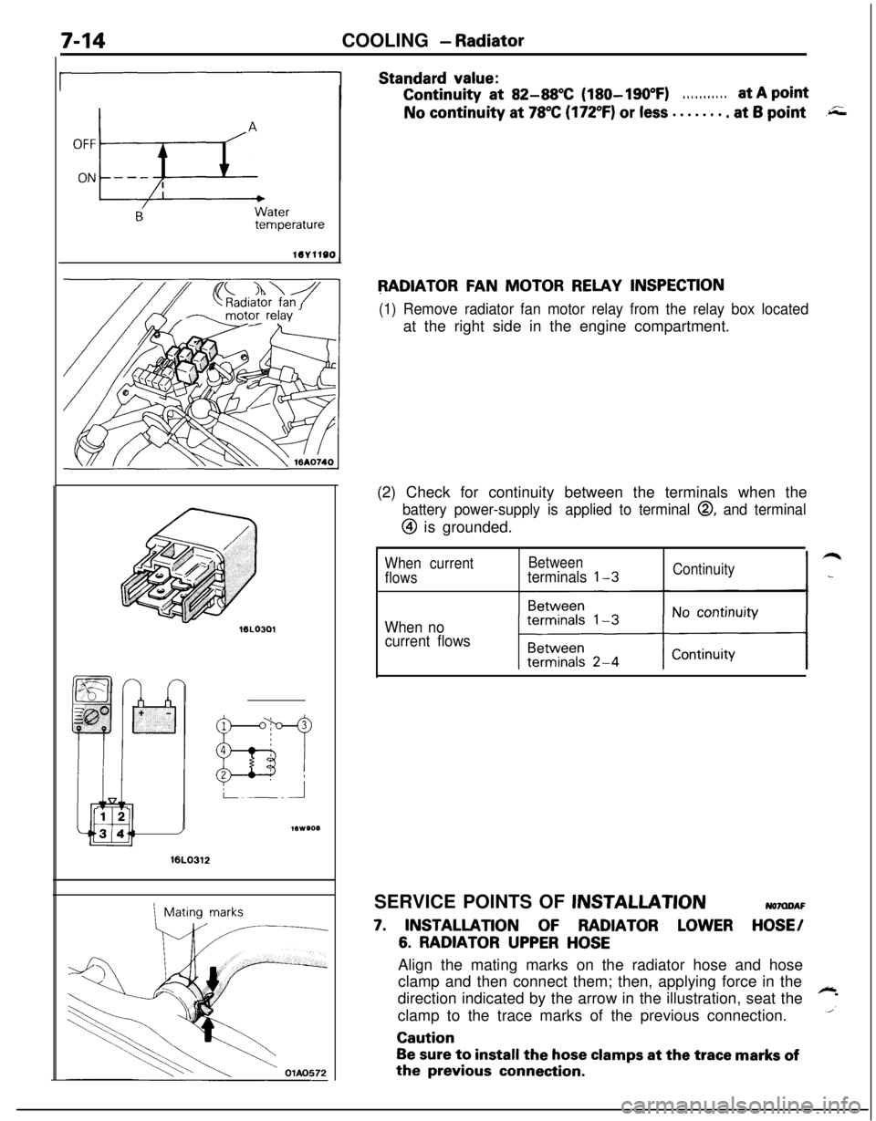
Standard value:Continuity
at 82-88X (180-190°F). . . . . . . . . . .at A pointNo continuity at
78°C (172°F) or less . . . . . . . . at 6 point.r;;;
RADIATOR FAN MOTOR RELAY INSPECTION
(1) Remove radiator fan motor relay from the relay box locatedat the right side in the engine compartment.
16LO312
1Mating marks(2) Check for continuity between the terminals when the
battery power-supply is applied to terminal 0, and terminal
@ is grounded.
When currentBetween
flowsterminals l-3Continuity
When no
current flowsSERVICE POINTS OF
JNSTALLATIONNOMDAF
7. INSTALLATION OF RADIATOR LOWER HOSE/
6. RADIATOR UPPER HOSEAlign the mating marks on the radiator hose and hose
clamp and then connect them; then, applying force in the
direction indicated by the arrow in the illustration, seat the
~
1clamp to the trace marks of the previous connection.Caution
Be sure to install the hose clamps at the trace marks ofthe
previous connection.