battery MITSUBISHI ECLIPSE 1991 Workshop Manual
[x] Cancel search | Manufacturer: MITSUBISHI, Model Year: 1991, Model line: ECLIPSE, Model: MITSUBISHI ECLIPSE 1991Pages: 1216, PDF Size: 67.42 MB
Page 528 of 1216
FUEL SYSTEM- MPI Svstem InsDection <2.0L DOHC Engine>
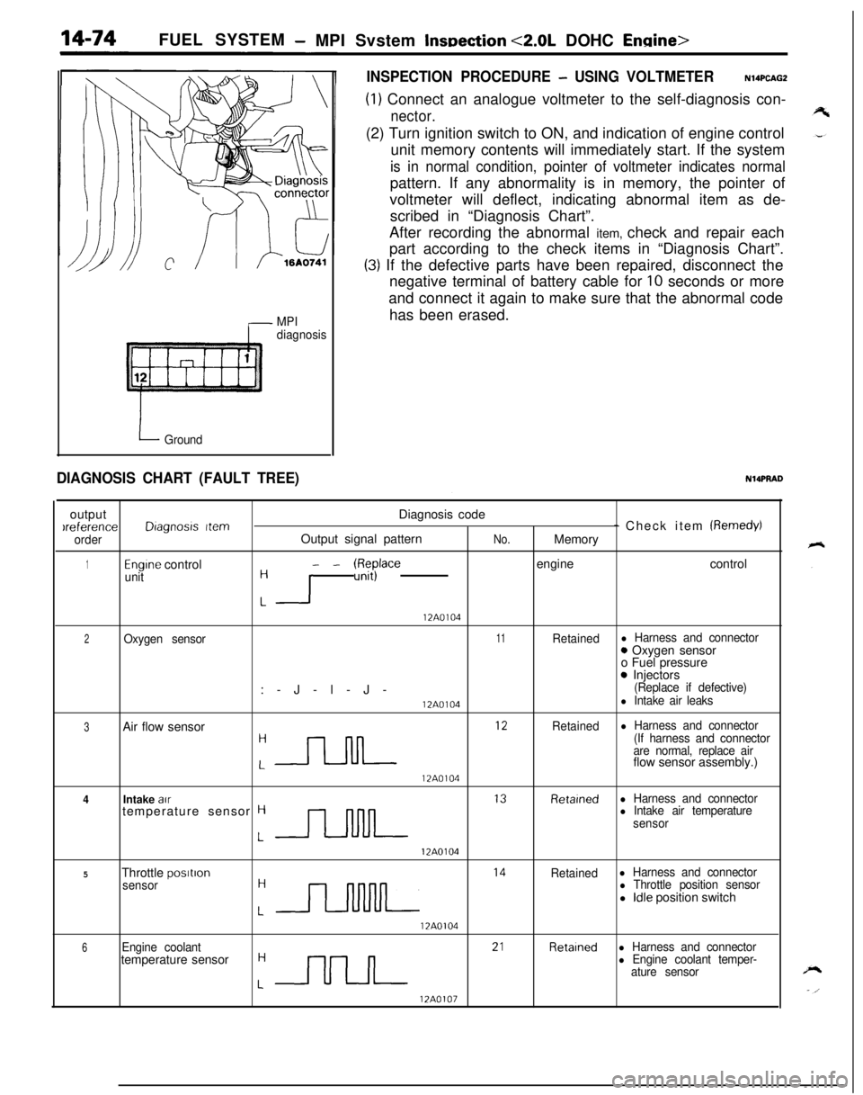
MPI
diagnosis
I Ground
INSPECTION PROCEDURE - USING VOLTMETERN14PCAGZ
(1) Connect an analogue voltmeter to the self-diagnosis con-
nector.(2) Turn ignition switch to ON, and indication of engine control
unit memory contents will immediately start. If the system
is in normal condition, pointer of voltmeter indicates normalpattern. If any abnormality is in memory, the pointer of
voltmeter will deflect, indicating abnormal item as de-
scribed in “Diagnosis Chart”.
After recording the abnormal item, check and repair each
part according to the check items in “Diagnosis Chart”.
(3) If the defective parts have been repaired, disconnect the
negative terminal of battery cable for
10 seconds or more
and connect it again to make sure that the abnormal code
has been erased.
DIAGNOSIS CHART (FAULT TREE)NlQPRADoutputDiagnosis codeIreference
Dragnosrs Item- Check item (Remedy)
orderOutput signal patternNo.Memory
1Engine controlunit- - W$$ace engine control: I
12A0104
2Oxygen sensor11Retainedl Harness and connector:-J-l-J-0 Oxygen sensor
o Fuel pressure
0 Injectors(Replace if defective)
12A0104l Intake air leaks
3Air flow sensor
:-rLJL ‘*
Retainedl Harness and connector
(If harness and connector
are normal, replace airflow sensor assembly.)
12A0104
4Intake au
J--lNlL l3
Retarnedl Harness and connectortemperature sensor Hl Intake air temperature
sensor
12A0104
5Throttle postron
:n l4
Retainedl Harness and connector
sensorl Throttle position sensorl Idle position switch
17A0104
6Engine coolant
:nn 2’
Retainedl Harness and connectortemperature sensorl Engine coolant temper-
ature sensor
12A0107
Page 532 of 1216
FUEL SYSTEM - MPI System Inspection <2.0L DOHC Engine>
6FUO999
Accelerator pedal
DepressedContinuity .
Non-conductive
(03 fl)
ReleasedIConductive (0 fl)I(4) Replace the idle position switch if faulty.
NOTE
For replacement procedure, refer to the idle position switch(fixed speed adjusting screw) adjustment section
(P.14-
52.).OXYGEN SENSOR
NllQDeJ
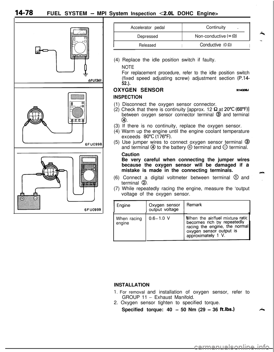
INSPECTION(1) Disconnect the oxygen sensor connector.
(2) Check that there is continuity [approx. 12
52 at 20°C (68”F)l
between oxygen sensor connector terminal @ and terminal
GO.(3) If there is no continuity, replace the oxygen sensor.
(4) Warm up the engine until the engine coolant temperature
exceeds
80°C (176°F).(5) Use jumper wires to connect oxygen sensor terminal
@and terminal
@ to the battery @ terminal and 0 terminal.
Caution
Be very careful when connecting the jumper wires
because the oxygen sensor will be damaged if a
mistake is made in the connecting terminals.
(6) Connect a digital voltmeter between terminal
@ and
terminal
0.(7) While repeatedly racing the engine, measure the ‘output
voltage of the oxygen sensor.
When racing
engineWhen the
air/fuel mixture raticINSTALLATION
1. For removal and installation of oxygen sensor, refer to
GROUP 11
- Exhaust Manifold.
2. Oxygen sensor tighten to specified torque.
Specified torque: 40
- 50 Nm (29 - 36 ft.lbs.)
Page 535 of 1216
_-
FUEL SYSTEM - MPI System Inspection <2.0L DOHC Engine>'I4181
OlLO22Z
CONTROL RELAY
INSPECTIONNWWAC
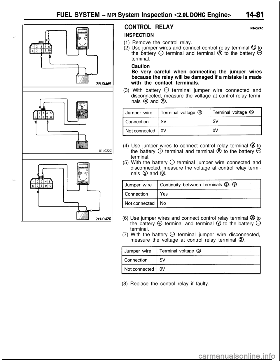
(1) Remove the control relay.
(2) Use jumper wires and connect control relay terminal
@I to
the battery
@ terminal and terminal @ to the battery 0
terminal.Caution
Be very careful when connecting the jumper wires
because the relay will be damaged if a mistake is made
with the contact terminals.
(3) With battery
0 terminal jumper wire connected and
disconnected, measure the voltage at control relay termi-
nals
@I and 0.(4) Use jumper wires to connect control relay terminal
@ to
the battery
@ terminal and terminal @ to the battery 0
terminal.(5) With the battery
@ terminal jumper wire connected and
disconnected, measure the voltage at control relay termi-
nals
@I and 0.
Continuity between terminals 0-0
)(6) Use jumper wires and connect control relay terminal
@ to
the battery
@ terminal and terminal @ to the battery 0
terminal.(7) With the battery
0 terminal jumper wire disconnected,
measure the voltage at control relay terminal
0.
31(8) Replace the control relay if faulty.
Page 536 of 1216
14-82FUEL SYSTEM - MPI System Inspection <2.0L DOHC Engine>
\ \\I \3FUO352
,\ \
\I \3FUO353
,\ ‘\R/
\ \\I \3FUo354
POWER TRANSISTORRefer to GROUP 8
- Ignition System
NlIAcQAl
a-4
AIR CONDITIONER POWER RELAYN14NCl.a -Refer to GROUP 24
- Air Conditioner.
PURGE CONTROL SOLENOID VALVEN14RCKARefer to GROUP 25
- Evaporative Emission Control System.
EGR CONTROL SOLENOID VALVE
N14NCURefer to GROUP 25
- Exhaust Gas Recirculation System.
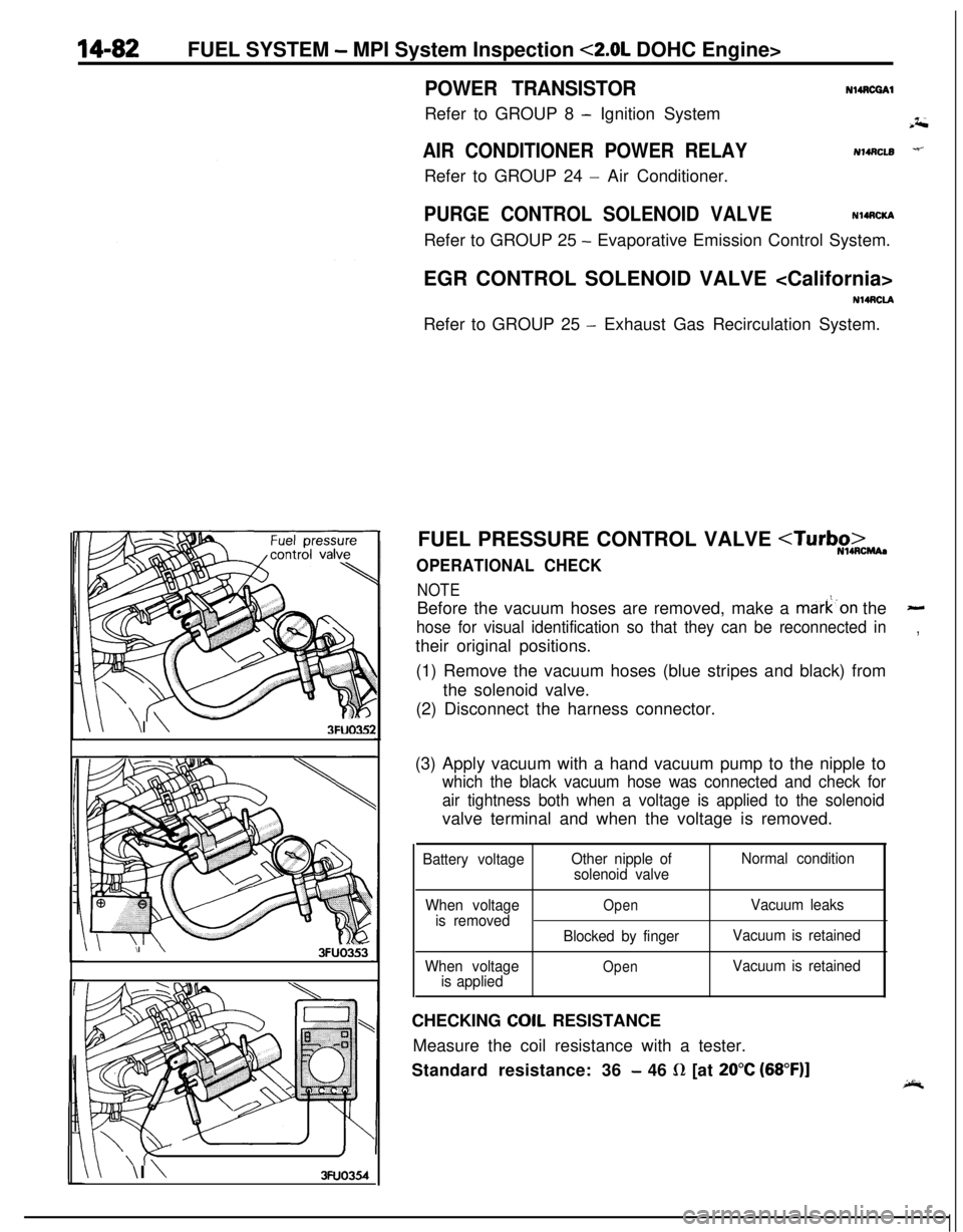
FUEL PRESSURE CONTROL VALVE
NOTEBefore the vacuum hoses are removed, make a mark’on the
-
hose for visual identification so that they can be reconnected in,their original positions.
(1) Remove the vacuum hoses (blue stripes and black) from
the solenoid valve.
(2) Disconnect the harness connector.
(3) Apply vacuum with a hand vacuum pump to the nipple to
which the black vacuum hose was connected and check for
air tightness both when a voltage is applied to the solenoidvalve terminal and when the voltage is removed.
Battery voltageOther nipple of
solenoid valveNormal condition
When voltage
is removed
When voltage
is applied
OpenVacuum leaks
Blocked by fingerVacuum is retained
OpenVacuum is retainedCHECKING
COIL RESISTANCE
Measure the coil resistance with a tester.
Standard resistance: 36
- 46 R [at 20°C (68”F)]
Page 556 of 1216
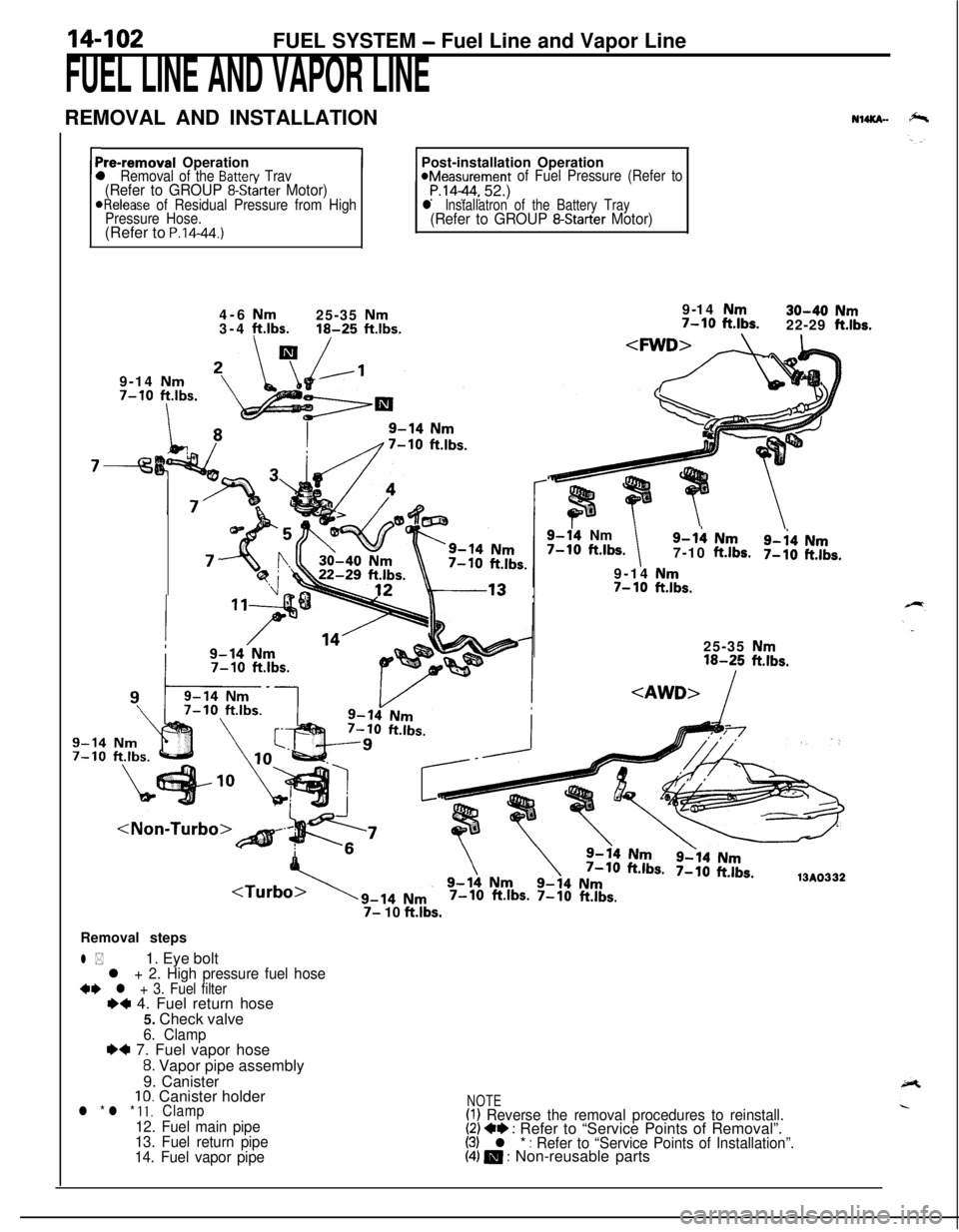
14-102FUEL SYSTEM - Fuel Line and Vapor Line
FUEL LINE AND VAPOR LINEREMOVAL AND INSTALLATION
NuKn-
rPre-removal Operationl Removal of the Batten/ Trav(Refer to GROUP 8-Starter Motor)ORelease of Residual Pressure from High
Pressure Hose.(Refer to
P.14-44.)
1Post-installation Operation*Measurement of Fuel Pressure (Refer toP.1444, 52.)l lnstallatron of the Battery Tray(Refer to GROUP 8-Starter Motor)4-6
Nm25-35 Nm3-4 ft.lbs.16-25 ftlbs.9-14 Nm7-10
ftlbs.
I
7-9-14
Nm30-40 Nm7-10 ft.lbs.22-29 ft.lbs.
9-14 Nm
7-10 ftlbs.
9-14Nm7-10 ft.lbs.9-h Nm
7-10ft.lbs.9-i4 Nm7-10ft.lbs.9-14
Nm7- 10ft.lbs.25-35
Nm16-25 ft.lbs.
7-10 ft.lbs. 7-10 ft.lbs.
7- 10 ft.lbs.Removal steps
l *1. Eye boltl + 2. High pressure fuel hose+e l + 3. Fuel filterI)+ 4. Fuel return hose
5. Check valve
6. Clamp~~ 7. Fuel vapor hose
8. Vapor pipe assembly
9. Canister
10. Canister holderl * l * 11.Clamp
12. Fuel main pipe
13. Fuel return pipe
14. Fuel vapor pipe
NOTE(I) Reverse the removal procedures to reinstall.(2) +e : Refer to “Service Points of Removal”.(3) l * : Refer to “Service Points of Installation”.(4) m : Non-reusable parts
Page 575 of 1216

AUTO-CRUISE CONTROL SYSTEM - Troubleshooting'14421
16A065i
Auto-cruise
16LOOS
SELF-DIAGNOSIS CHECKSelf-diagnosis checking is performed when there has been an
automatic cancellation, without cancel switch
operati’on.(1) The following method can be used for checking the
diagnosis. Note that the diagnosis check connector is
located under the driver’s side instrument panel.
Connect a voltmeter between the ground terminal and the
terminal for auto-cruise control of the diagnosis check
connector.It is possible to discover which circuit is the cause of the
cancellation by verifying the indication shown by the
voltmeter with the display patterns shown on the next
page.(2) When the diagnosis code No. is displayed, inspect accord-
ing to the inspection chart No. related to each code No.
NOTECanceling the diagnosis codes
The diagnosis codes remain in memory until the battery is
turned off but they can be canceled in the following ways
without disconnecting the battery terminals.
1. By turning on the ignition switch
2.By turning the cruise switch ON while the SET switch is ONand then, within 1 second, turning the RESUME switch
ON. (Put into condition for input check reception)
3.By turning ON set SET switch and stop light switch at the
same time and continuing the ON condition for 5 seconds
or more.
4.By checking that the diagnosis codes are canceled using avoltmeter.
Page 576 of 1216
14-122AUTO-CRUISE CONTROL SYSTEM - Troubleshooting
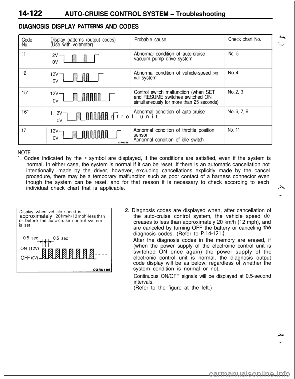
DIAGNOSIS DISPLAY PAlTERNS AND CODES
CodeNo.
11
Display patterns (output codes)(Use with voltmeter)
“,;1 fl 1 j--
Probable cause
Abnormal condition of auto-cruise
vacuum pump drive system
Check chart No.
No. 5
12Abnormal condition of vehicle-speed sig-No.4nal system
15"16"12vControl switch malfunction (when SETNo.2, 3
and RESUME switches switched ONovsimultaneously for more than 25 seconds)
I ‘,“,-I r
Abnormal condition of auto-cruiseNo.6,7,8control unit
17Abnormal condition of throttle positionNo. 11
sensorAbnormal condition of idle switch,3*0356
NOTE
1. Codes indicated by the* symbol are displayed, if the conditions are satisfied, even if the system is
normal. In either case, the system is normal if it can be reset. If there is an automatic cancellation not
intentionally made by the driver, however, excluding cancellations explicitly made by the cancel
procedure, there may be a temporary malfunction such as poor contact of a harness connector even
though the system can be reset, and for that reason it is necessary to check according to each
individual check chart that is applicable.Display
when vehicle speed isapproximately 20 km/h (12 mph) less thanor before the auto-cruise control systemis set
ON (12V)
OFF (OV)2. Diagnosis codes are displayed when, after cancellation of
the auto-cruise control system, the vehicle speed
de-creases to less than approximately 20 km/h (12 mph), and
are canceled by turning OFF the battery or canceling the
diagnosis codes. (Refer to
P.14-121.)After the diagnosis codes in the memory are erased, if
(when the power supply of the electroinc control unit is
switched ON once again) the power supply of the
electronic control unit is normal, the diagnosis output
code display will be as below, regardless of whether the
system condition is normal or not.
Continuous ON/OFF signals will be displayed at 0.5-second
intervals.(Refer to the figure at the left.)
Page 592 of 1216
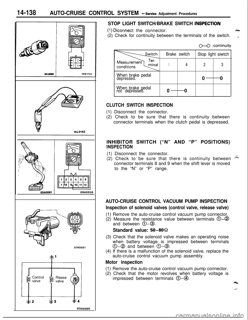
14-138AUTO-CRUISE CONTROL SYSTEM - Service Adjustment Procedures
07A0051
07AOO50
STOP LIGHT SWITCH/BRAKE SWITCH ItiSPECTlON
(1) Diconnect the connector.66(2) Check for continuity between the terminals of the switch.
_
When brake pedaldepressed.
When brake pedalnot depressed.
m :continuity
Brake switch
Stop light siwtch
142300
00
CLUTCH SWITCH INSPECTION(1) Disconnect the connector.
(2) Check to be sure that there is continuity between
connector terminals when the clutch pedal is depressed.
INHIBITOR SWITCH (“N” AND “P” POSITIONS)
INSPECTION(1) Disconnect the connector.
(2) Check to be sure that there is continuity between
Aconnector terminals 8 and 9 when the shift lever is moved
to the “N” or “P” range.
AUTO-CRUISE CONTROL VACUUM PUMP INSPECTION
Inspection of solenoid valves (control valve, release valve)(1) Remove the auto-cruise control vacuum pump connector.
(2) Measure the resistance value between terminals
0-0and between
0-0.
Standard value: 50-6OQ
(3) Check that the solenoid valve makes an operating noise
when battery voltage is impressed between terminals
0-0 and between 0-0.(4) If there is a malfunction of the solenoid valve, replace the
auto-cruise control vacuum pump assembly.
Motor inspection(1) Remove the auto-cruise control vacuum pump connector.
(2) Check that the motor revolves when battery voltage is
impressed between terminals @-@I.
@k
Page 713 of 1216
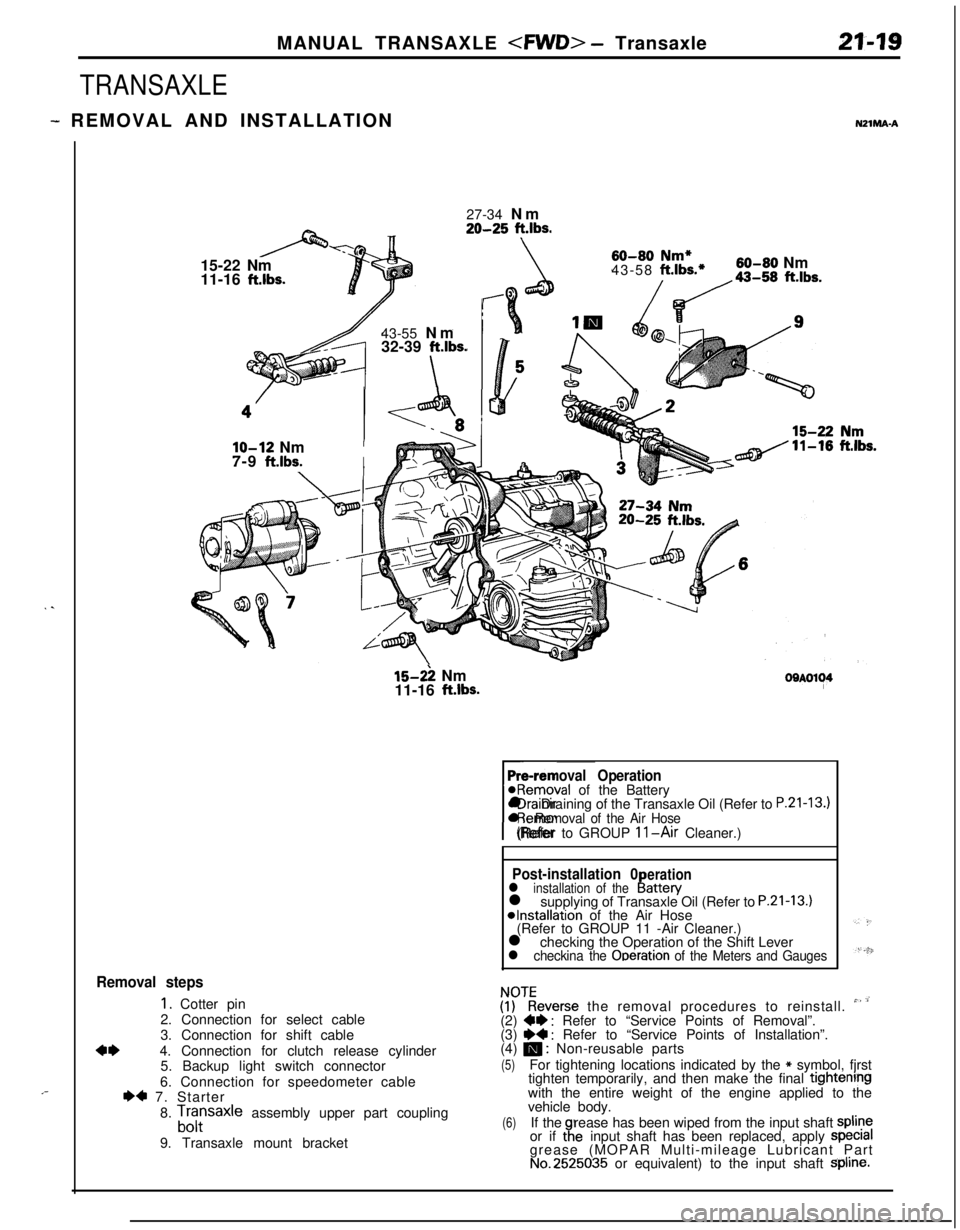
MANUAL TRANSAXLE
TRANSAXLE
- REMOVAL AND INSTALLATIONNZlMA-A
. .
,-27-34 Nm
20-25 ft.lbs.15-22 Nm
11-16
ft.lbs.43-55 Nm
32-39
ft.lbs.
\
60-80 Nm*43-58 ft.lbs.*60-80 Nm
/da-,, ft.lbs.
lo-12 NmI7-9
ft.lbs.I
15-2: Nm
11-16 ft.lbs.OOAOl~4
Pre-removal Operation@Removal of the Battery
rl Draining of the Transaxle Oil (Refer to
P.21-13.)l Removal of the Air Hose(Refer to GROUP 11-Air Cleaner.)
Post-installation 0erationl installation of theI!attery
l supplying of Transaxle Oil (Refer to P.21-13.)*Installation of the Air Hose
(Refer to GROUP 11 -Air Cleaner.)
l checking the Operation of the Shift Lever
l checkina the Ooeration of the Meters and Gauges
Removal steps
1. Cotter pin
2. Connection for select cable
3. Connection for shift cable
4*4. Connection for clutch release cylinder
5. Backup light switch connector
6. Connection for speedometer cable
I)* 7. Starter
8.
Lfrsaxle assembly upper part coupling
9. Transaxle mount bracket
ZKeverse the removal procedures to reinstall. ” ’(2) W : Refer to “Service Points of Removal”.
(3) ~~ : Refer to “Service Points of Installation”.
(4) m : Non-reusable parts
(5)For tightening locations indicated by the * symbol, fjrst
tighten temporarily, and then make the final tightenrngwith the entire weight of the engine applied to the
vehicle body.
(6)If therease has been wiped from the input shaft spline
or if taeinput shaft has been replaced, apply specralgrease (MOPAR Multi-mileage Lubricant Part
No.2525035 or equivalent) to the input shaft Spline.
Page 776 of 1216
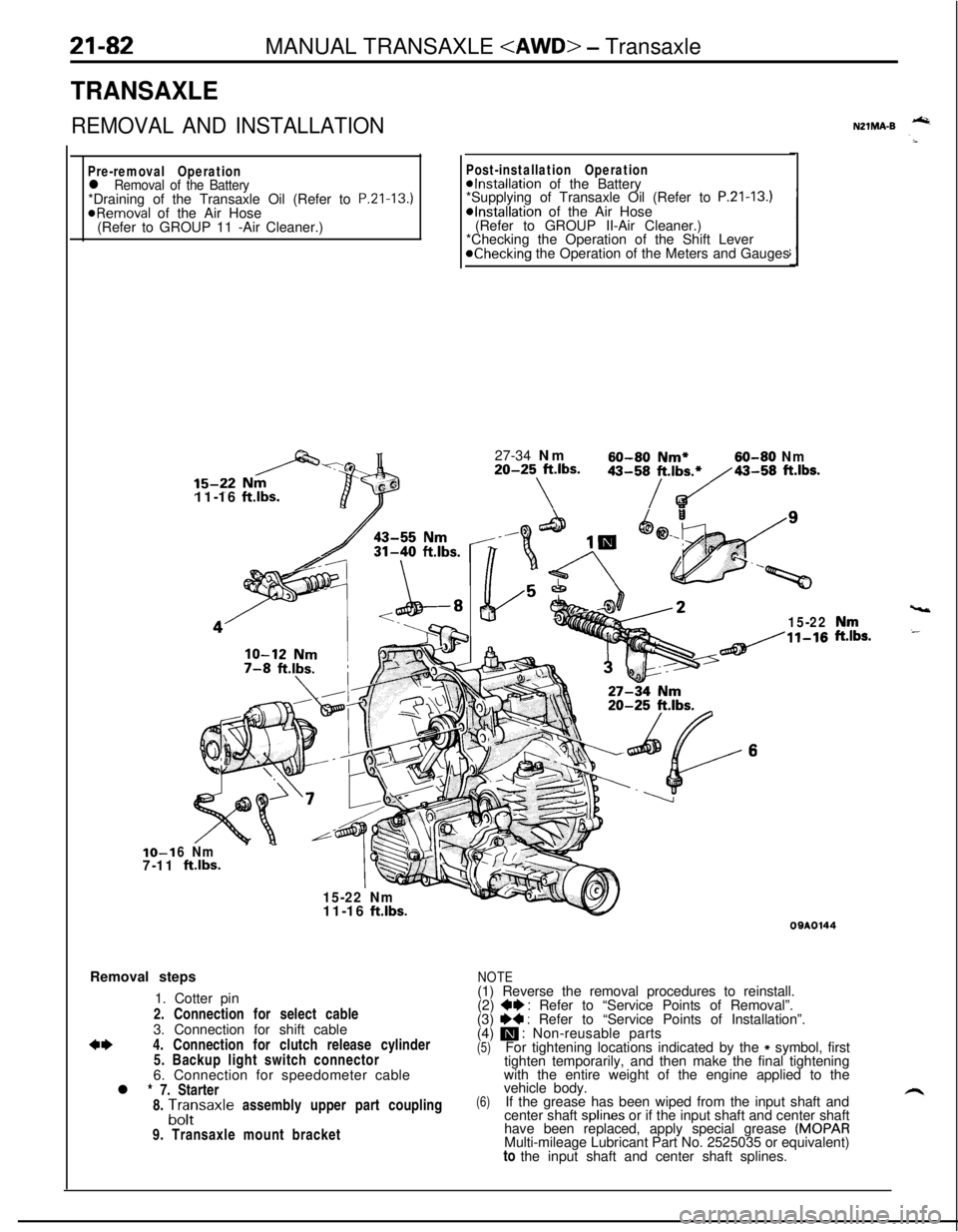
21-82MANUAL TRANSAXLE
TRANSAXLE
REMOVAL AND INSTALLATION
Pre-removal Operationl Removal of the Battery*Draining of the Transaxle Oil (Refer to P.Zl-13.)
@Removal of the Air Hose
(Refer to GROUP 11 -Air Cleaner.)IO-1
7-1111-16
ftlbs.
Post-installation Operation@Installation of the Battery
*Supplying of Transaxle Oil (Refer to P.21-13.)*Installation of the Air Hose
(Refer to GROUP II-Air Cleaner.)
*Checking the Operation of the Shift Lever
@Checking the Operation of the Meters and Gauges
27-34 Nm
60-60 Nm*60-80 Nm20-25 ft.lbs.
\
43-58/t.,b~43-58 ft.lbs.
15-22
6 Nm
ftlbs.
15-22 Nm
vt11-16
ft.lbs.Removal steps
1. Cotter pin
2. Connection for select cable
3. Connection for shift cable
*I)4. Connection for clutch release cylinder
5. Backup light switch connector
6. Connection for speedometer cable
l * 7. Starter
8.
A;;saxle assembly upper part coupling
9. Transaxle mount bracket
NZlMA-B -
,“rr,s.
09AOl44
NOTE(1) Reverse the removal procedures to reinstall.
(2)
+e : Refer to “Service Points of Removal”.
(3) I)+ : Refer to “Service Points of Installation”.
(4) m : Non-reusable parts(5)For tightening locations indicated by the * symbol, first
tighten temporarily, and then make the final tightening
with the entire weight of the engine applied to the
(6)vehicle body.
If the grease has been wiped from the input shaft and
center shaft splines or if the input shaft and center shaft
have been replaced, apply special grease
(MOPARMulti-mileage Lubricant Part No. 2525035 or equivalent)
to the input shaft and center shaft splines.