battery MITSUBISHI ECLIPSE 1991 Workshop Manual
[x] Cancel search | Manufacturer: MITSUBISHI, Model Year: 1991, Model line: ECLIPSE, Model: MITSUBISHI ECLIPSE 1991Pages: 1216, PDF Size: 67.42 MB
Page 873 of 1216
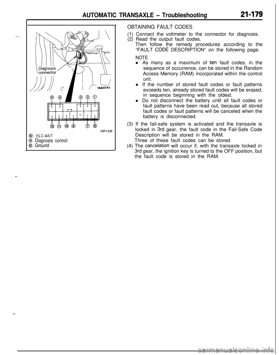
AUTOMATIC TRANSAXLE - Troubleshooting21-179
@: ELC-4PJT
@I: Diagnosis control
0: Ground
16R1336
OBTAINING FAULT CODES(1) Connect the voltmeter to the connector for diagnosis.
(2) Read the output fault codes.
Then follow the remedy procedures according to the
“FAULT
CODE DESCRIPTION” on the following page.
NOTEl As many as a maximum of
terr fault codes, in the
sequence of occurrence, can be stored in the Random
Access Memory (RAM) incorporated within the control
unit.l If the number of stored fault codes or fault patterns
exceeds ten, already stored fault codes will be erased,
in sequence beginning with the oldest.
l Do not disconnect the battery until all fault codes or
fault patterns have been read out, because all stored
fault codes or fault patterns will be canceled when the
battery is disconnected.
(3) If the fail-safe system is activated and the transaxle is
locked in
3rd gear, the fault code in the Fail-Safe Code
Description will be stored in the RAM.
Three of these fault codes can be stored.
(4) The
cancelation will occur if, with the transaxle locked in
3rd gear, the ignition key is turned to the OFF position, but
the fault code is stored in the RAM.
Page 919 of 1216
AUTOMATIC TRANSAXLE - Transaxle Assembly
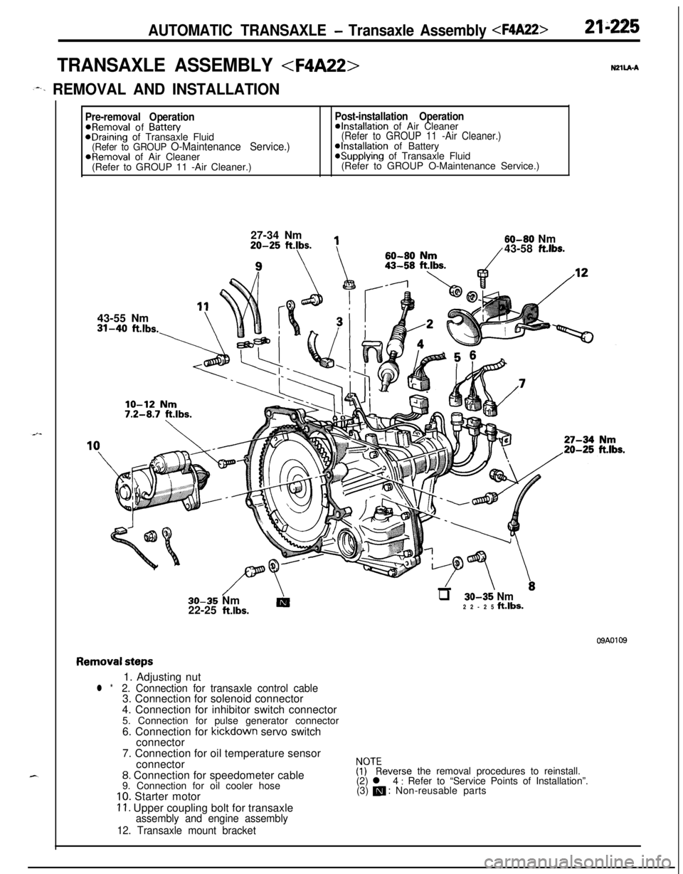
TRANSAXLE ASSEMBLY
,--. REMOVAL AND INSTALLATION
Pre-removal OperationPost-installation Operation@Removal of Battew@Installation of Air CleaneraDraining of Transaxle Fluid(Refer to GROUP 11 -Air Cleaner.)(Refer to GROUP O-Maintenance Service.)@Installation of BatteryaRemoval of Air Cleaner*Supplying of Transaxle Fluid
(Refer to GROUP 11 -Air Cleaner.)(Refer to GROUP O-Maintenance Service.)
27-34 Nm20-25
ftlbs.
1143-55 Nm31-40
ft.lbs.-\60-80
flrn60-80 Nm/43-58 ft.lbs.
//\-LTT \.30-35 Nm
AIq 30-35 Nm22-25 klbs.22-25 ft.lbs.
09A0109
Removal steps1. Adjusting nut
l *2. Connection for transaxle control cable3. Connection for solenoid connector
4. Connection for inhibitor switch connector
5. Connection for pulse generator connector
6. Connection for kickdown servo switch
connector
7. Connection for oil temperature sensor
connector
8. Connection for speedometer cable
9. Connection for oil cooler hose
10. Starter motor
11. Upper coupling bolt for transaxleassembly and engine assembly
12. Transaxle mount bracket
$?everse the removal procedures to reinstall.
(2) l 4 : Refer to “Service Points of Installation”.
(3) m : Non-reusable parts
Page 953 of 1216
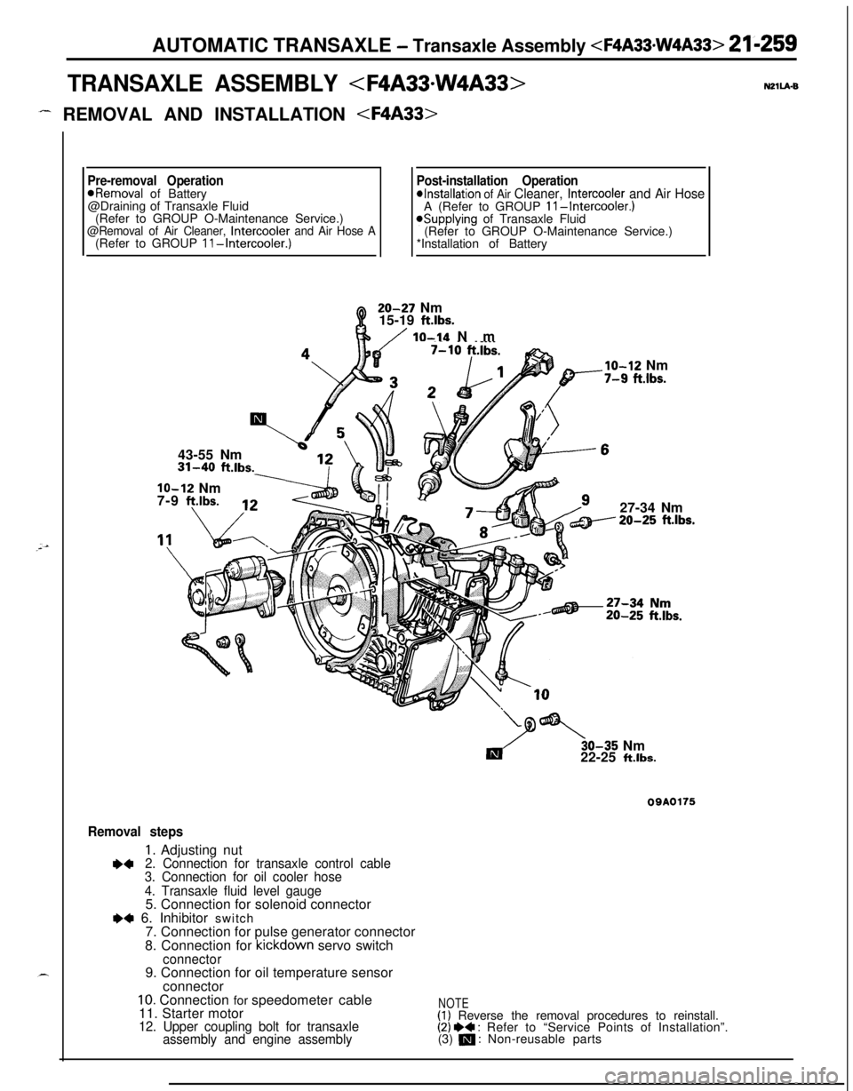
AUTOMATIC TRANSAXLE - Transaxle Assembly
TRANSAXLE ASSEMBLY
- REMOVAL AND INSTALLATION
Pre-removal OperationPost-installation Operation*Removal of Battery*Installation of Air Cleaner, Intercooler and Air Hose@Draining of Transaxle Fluid
A (Refer to GROUP II-Intercooler.)(Refer to GROUP O-Maintenance Service.)
@Removal of Air Cleaner, Intercooler and Air Hose A*Supplying of Transaxle Fluid
(Refer to GROUP O-Maintenance Service.)
(Refer to GROUP II-Intercooler.)*Installation of Battery20-27 Nm
15-19
ft.lbs.
/ IO-14 Nm
43-55 Nm31-40
ft.lbs.
lo-12 Nm
7-9 f?.lbs.
___.Ibs.
lo-12 Nm-7-9 fi.lbs.27-34 Nm20-25
ft.lbs.30-35 Nm
22-25
ft.lbs.
09A0175
Removal steps
1. Adjusting nut+42. Connection for transaxle control cable
3. Connection for oil cooler hose
4. Transaxle fluid level gauge5. Connection for solenoid connector
e+ 6. Inhibitor switch
7. Connection for pulse generator connector
8. Connection for kickdown servo switch
connector9. Connection for oil temperature sensor
connector
10. Connection for speedometer cable
11. Starter motor
12. Upper coupling bolt for transaxle
assembly and engine assembly
NOTE(1) Reverse the removal procedures to reinstall.(2) I)+ : Refer to “Service Points of Installation”.
(3) m : Non-reusable parts
Page 1048 of 1216
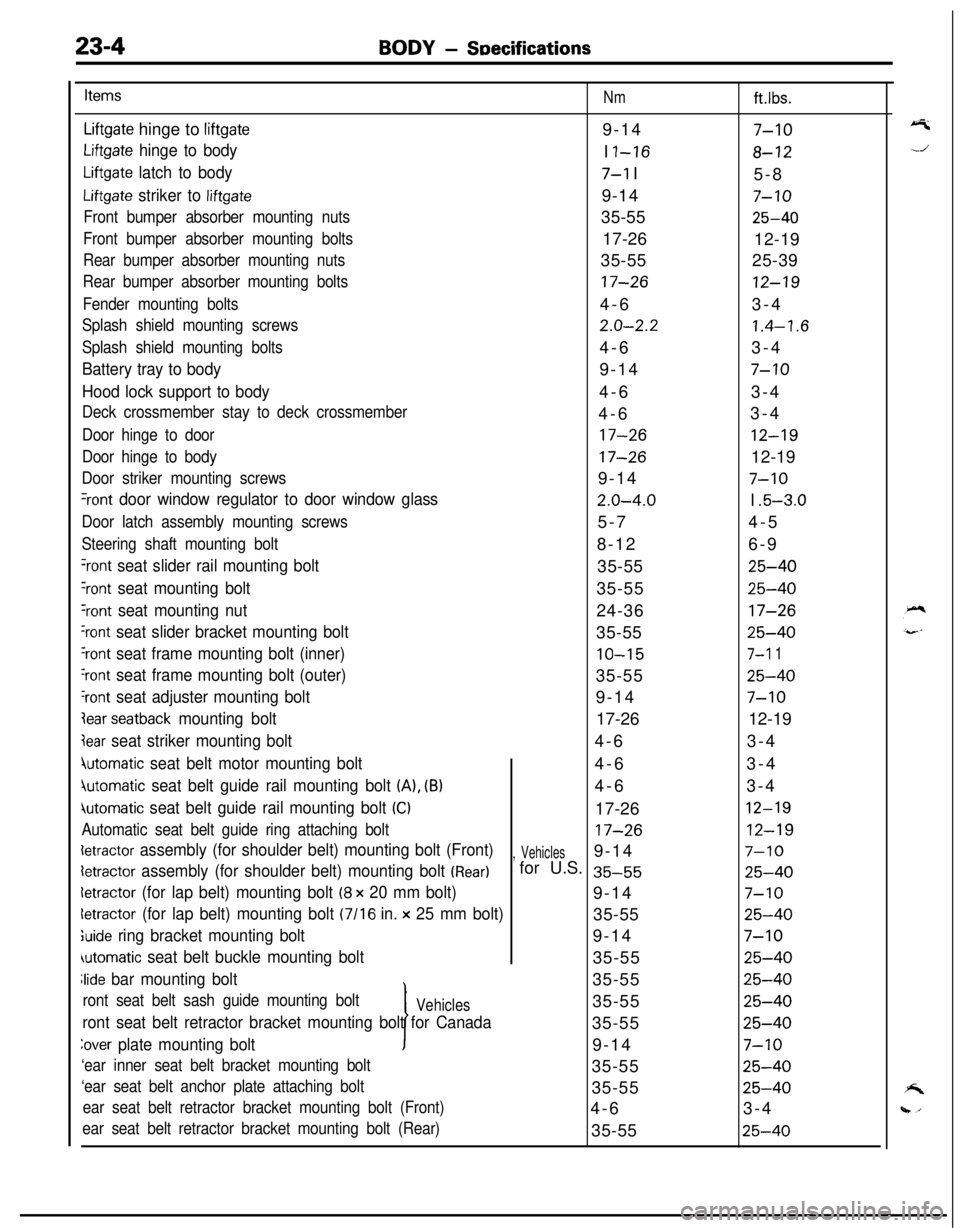
23-4BODY - SDecifications
Items
Nmft.lbs.
Liftgate hinge to liftgate9-147-10
Liftgate hinge to bodyI I-168-12
Liftgate latch to body7-l I
5-8
Liftgate striker to liftgate9-147-10
Front bumper absorber mounting nuts35-5525-40
Front bumper absorber mounting bolts17-26
12-19
Rear bumper absorber mounting nuts35-5525-39
Rear bumper absorber mounting bolts17-2612-19
Fender mounting bolts4-63-4
Splash shield mounting screws2.0-2.21.4-1.6
Splash shield mounting bolts4-63-4
Battery tray to body9-147-10
Hood lock support to body4-63-4
Deck crossmember stay to deck crossmember4-63-4
Door hinge to door17-2612-19
Door hinge to body17-2612-19
Door striker mounting screws9-147-10
%ont door window regulator to door window glass2.0-4.0I .5-3.0
Door latch assembly mounting screws5-74-5
Steering shaft mounting bolt8-126-9
‘rant seat slider rail mounting bolt35-5525-40
Yont seat mounting bolt35-5525-40
‘rant seat mounting nut24-3617-26
‘rant seat slider bracket mounting bolt35-5525-40
‘rant seat frame mounting bolt (inner)10-157-l 1
‘rant seat frame mounting bolt (outer)35-5525-40
‘rant seat adjuster mounting bolt9-147-10
lear seatback mounting bolt17-2612-19
jear seat striker mounting bolt4-63-4
4utomatic seat belt motor mounting bolt4-63-4
jutomatic seat belt guide rail mounting bolt (A), (B)4-63-4
iutomatic seat belt guide rail mounting bolt (Cl17-2612-19
Automatic seat belt guide ring attaching bolt17-2612-19
detractor assembly (for shoulder belt) mounting bolt (Front), Vehicles9-147-10
detractor assembly (for shoulder belt) mounting bolt (Rear)for U.S. 35-5525-40
detractor (for lap belt) mounting bolt (8 x 20 mm bolt)9-147-10
letractor (for lap belt) mounting bolt (7116 in. x 25 mm bolt)35-5525-40
;uide ring bracket mounting bolt9-147-10
automatic seat belt buckle mounting bolt35-5525-40
Jide bar mounting bolt
I35-55
25-40
ront seat belt sash guide mounting boltVehicles35-5525-40
ront seat belt retractor bracket mounting bolt for Canada35-5525-40
Zover plate mounting bolt9-147-10
‘ear inner seat belt bracket mounting bolt35-5525-40
‘ear seat belt anchor plate attaching bolt35-5525-40
ear seat belt retractor bracket mounting bolt (Front)4-63-4
ear seat belt retractor bracket mounting bolt (Rear)35-5525-40
Page 1060 of 1216
23-16BODY - Troubleshooting
OPERATION
Key-reminder warning0 Battery voltage is always supplied, through sub
fusible link No.
@, to the key-reminder switch.0 When the driver’s seat door is opened while the
ignition key is still in the key cylinder, the door
switch is switched ON, electricity flows to sub
fusible link No.
0, the key-reminder switch, the
buzzer, the door switch, and ground, and the
buzzer sounds.
Seat belt warning0 Battery voltage is applied, through fuse No.
0,to the seat belt timer when the ignition key is at
the “ON” position.0 Electricity flows to sub fusible link No. @, the
key-reminder switch, the seat belt warning light,
the seat belt timer, and ground, and the seat beltwarning light illuminates for approx. 6 seconds.0
If the driver does not buckle the seat belt, the seatbelt switch is switched ON, electricity flows to
sub fusible link No. @, the key-reminder switch,the buzzer, the seat belt switch, the seat belt
warning timer, and ground, and the buzzer
sounds for approx. 6 seconds.0 When the driver buckles the seat belt, the seat
belt switch is switched OFF and the buzzer stops.
TROUBLESHOOTING HINTS
Key-reminder warningThe key-reminder warning doesn’t sound.
(1) The seat belt warning function is OK.
l Check the door switch.
(2) The seat belt warning also doesn’t function.0 Check the buzzer.
Seat belt warning1. The seat belt warning doesn’t function.
(1) The seat belt warning light illuminates.0 Check the seat belt switch.
(2) The seat belt warning light also does not
function (but the key-reminder warning
functions normally. 10 Check the seat belt timer.
(3) The seat belt warning light also does not
function (and the key-reminder warning also
does not function).0 Check the key-reminder switch.
2.The buzzer doesn’t stop even though the driver’s
seat belt has been buckled.0 Check the seat belt switch.
3.The seat belt warning light doesn’t illuminate (but
the buzzer sounds).l Check the light bulb.
’ I
Page 1111 of 1216
BODY - Door Glass and Reaulator/Power Window23-67
POWER WINDOW
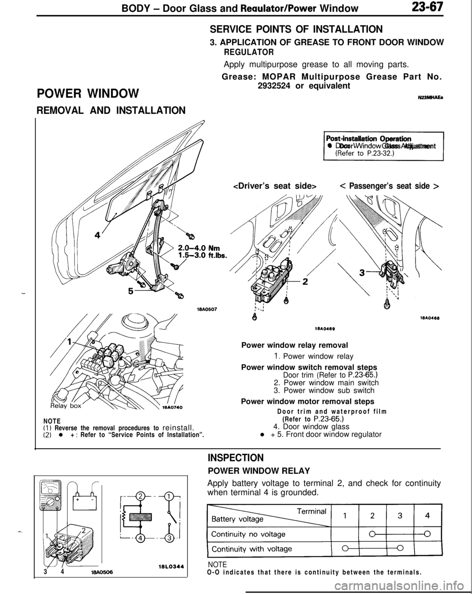
REMOVAL AND INSTALLATIONSERVICE POINTS OF INSTALLATION3. APPLICATION OF GREASE TO FRONT DOOR WINDOW
REGULATORApply multipurpose grease to all moving parts.
Grease: MOPAR Multipurpose Grease Part No.
2932524 or equivalent
N23MHAEa
71l Door Window Glass Adjustment
< Passenger’s seat side >NOTE
(1) Reverse the removal procedures to reinstall.(2) l + : Refer to “Service Points of Installation”.
1810469Power window relay removal
1. Power window relay
Power window switch removal steps
Door trim (Refer to P.23-65.)2. Power window main switch
3. Power window sub switch
Power window motor removal steps
Door trim and waterproof film
(Refer to
P.23-65.)4. Door window glass
l + 5. Front door window regulator
16l.03443 416AO606
INSPECTIONPOWER WINDOW RELAY
Apply battery voltage to terminal 2, and check for continuity
when terminal 4 is grounded.
NOTEO-O indicates that there is continuity between the terminals.
Page 1112 of 1216
23-68BODY - Power Window
Power
window
lock
switch
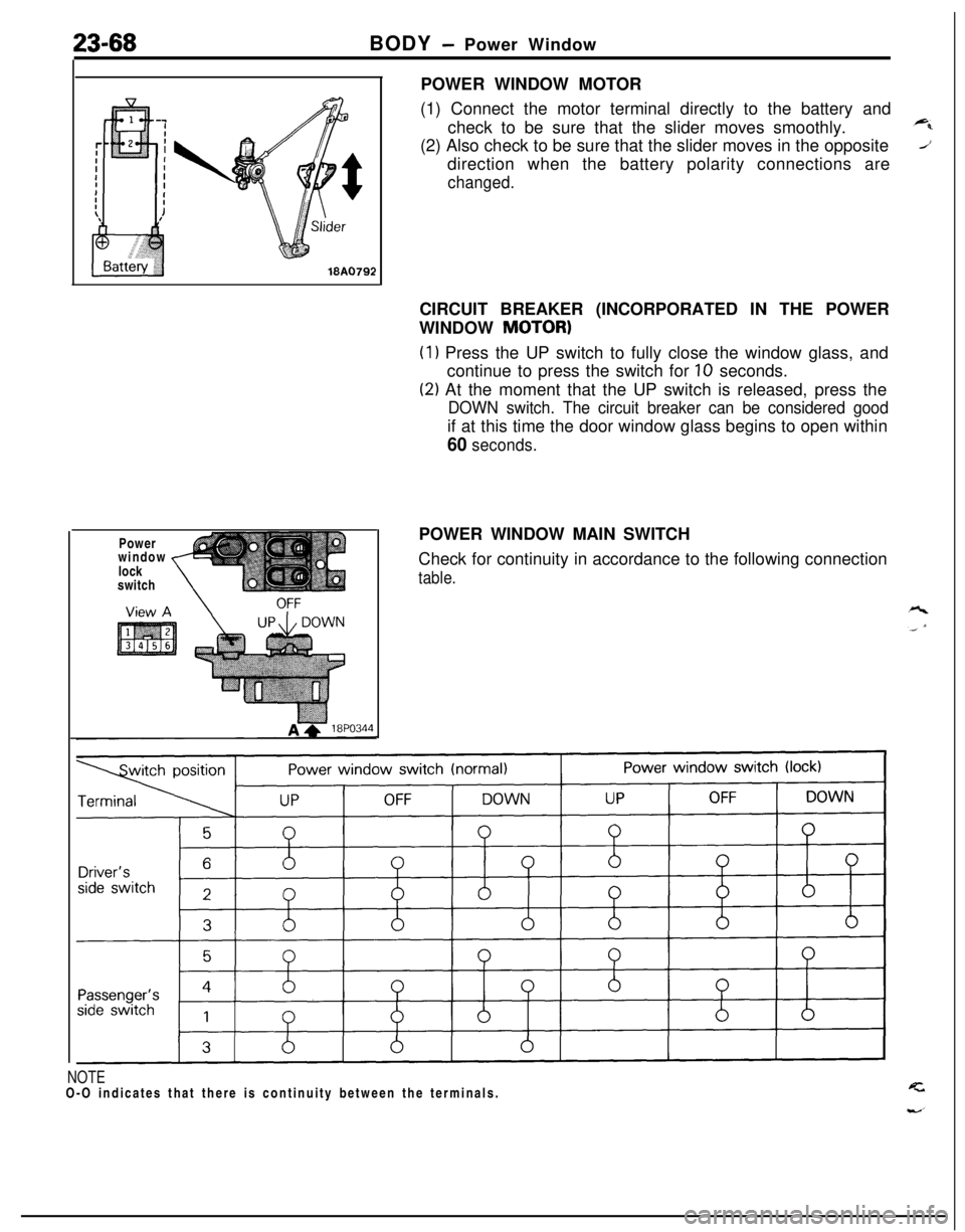
,POWER WINDOW MOTOR
(1) Connect the motor terminal directly to the battery and
check to be sure that the slider moves smoothly.
(2) Also check to be sure that the slider moves in the opposite
direction when the battery polarity connections are
changed.CIRCUIT BREAKER (INCORPORATED IN THE POWER
WINDOW
MOTOR)
(1) Press the UP switch to fully close the window glass, and
continue to press the switch for
10 seconds.
(2) At the moment that the UP switch is released, press the
DOWN switch. The circuit breaker can be considered goodif at this time the door window glass begins to open within
60 seconds.POWER WINDOW MAIN SWITCH
Check for continuity in accordance to the following connection
table.
NOTEO-O indicates that there is continuity between the terminals.
Page 1115 of 1216
BODY - Central Door Locking System/Door Runchannel23-71View A
18A0064-
L
DOOR RUNCHANNEL
REMOVAL AND INSTALLATION
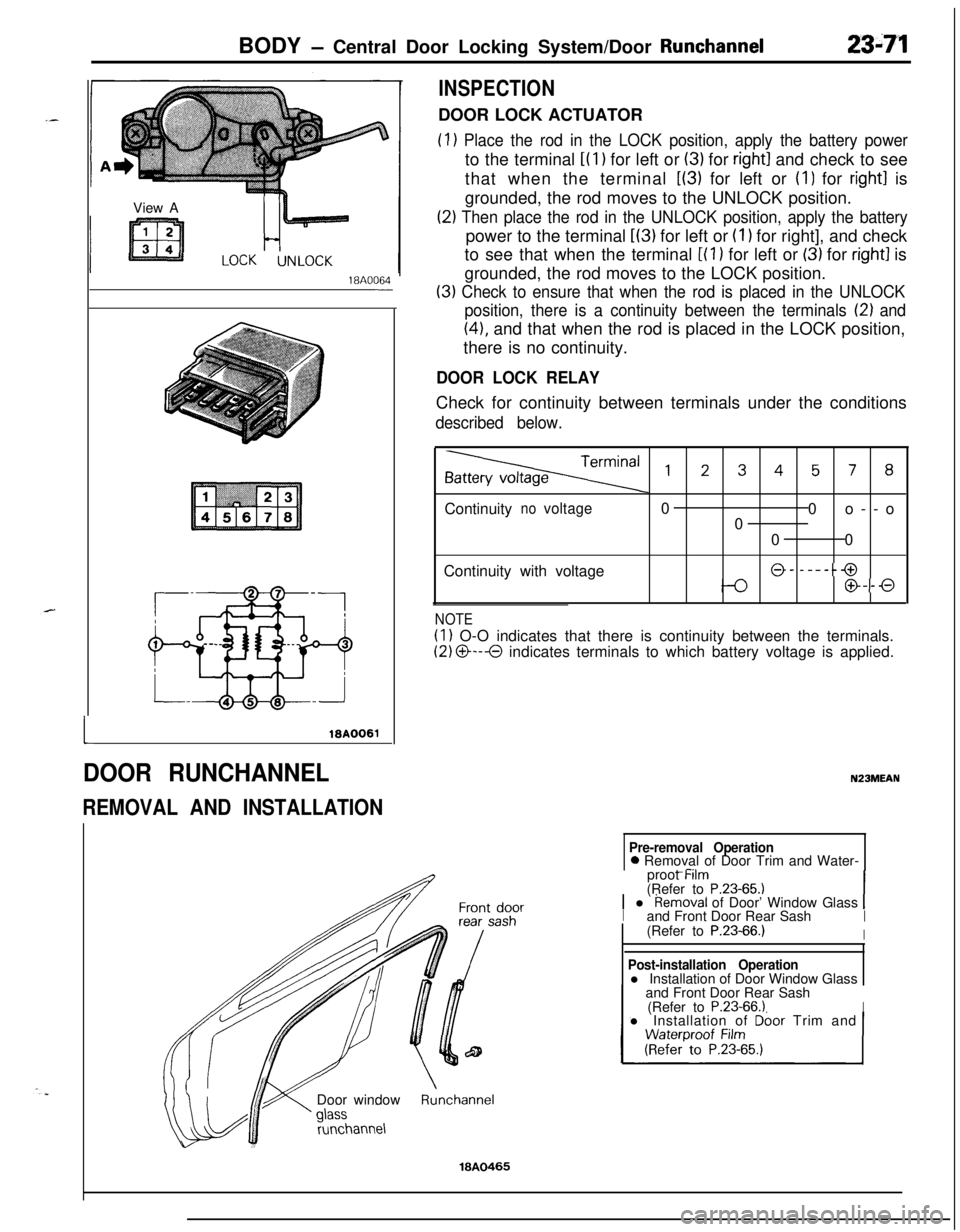
INSPECTIONDOOR LOCK ACTUATOR
(1) Place the rod in the LOCK position, apply the battery powerto the terminal
i(l) for left or (3) for right1 and check to see
that when the terminal
L(3) for left or (I) for right1 is
grounded, the rod moves to the UNLOCK position.
(2) Then place the rod in the UNLOCK position, apply the batterypower to the terminal
L(3) for left or (I 1 for right], and check
to see that when the terminal
[(l ) for left or (3) for right1 is
grounded, the rod moves to the LOCK position.
(3) Check to ensure that when the rod is placed in the UNLOCK
position, there is a continuity between the terminals
12) and
(41, and that when the rod is placed in the LOCK position,
there is no continuity.
DOOR LOCK RELAYCheck for continuity between terminals under the conditions
described below.
,2345, 8Continuity
novoltage0
0o--o
0
00
Continuity with voltage
@- -----@
@--0
NOTE
(1) O-O indicates that there is continuity between the terminals.
(2) O---O indicates terminals to which battery voltage is applied.
N23MEAN
Pre-removal Operation0 Removal of Door Trim and Water-
_ -..proot Mm
(Refer to
P.23-65.11 l Removal of Door’ Window Glass 1Iand Front Door Rear SashI(Refer to P.23-66.)IDoor window
runchannel
Post-installation Operationl Installation of Door Window Glass
and Front Door Rear Sash
(Refer to
P.23-66.1Il Installation of Dbor Trim and
Runchannel
18A0465
Page 1117 of 1216
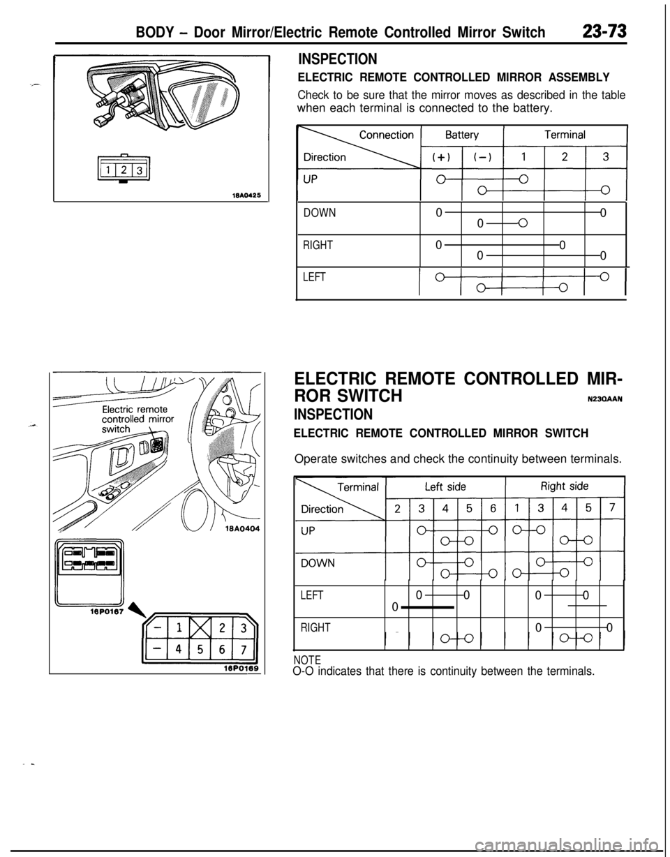
BODY - Door Mirror/Electric Remote Controlled Mirror Switch23-73
18AO425
16P0109-
INSPECTION
ELECTRIC REMOTE CONTROLLED MIRROR ASSEMBLY
Check to be sure that the mirror moves as described in the tablewhen each terminal is connected to the battery.
DOWN0
0
00
RIGHT0
0
0
0
LEFT
IOI
ELECTRIC REMOTE CONTROLLED MIR-
ROR SWITCH
N23QAAN
INSPECTION
ELECTRIC REMOTE CONTROLLED MIRROR SWITCHOperate switches and check the continuity between terminals.
LEFT00
00
0
RIGHT00
NOTEO-O indicates that there is continuity between the terminals.
..
Page 1139 of 1216
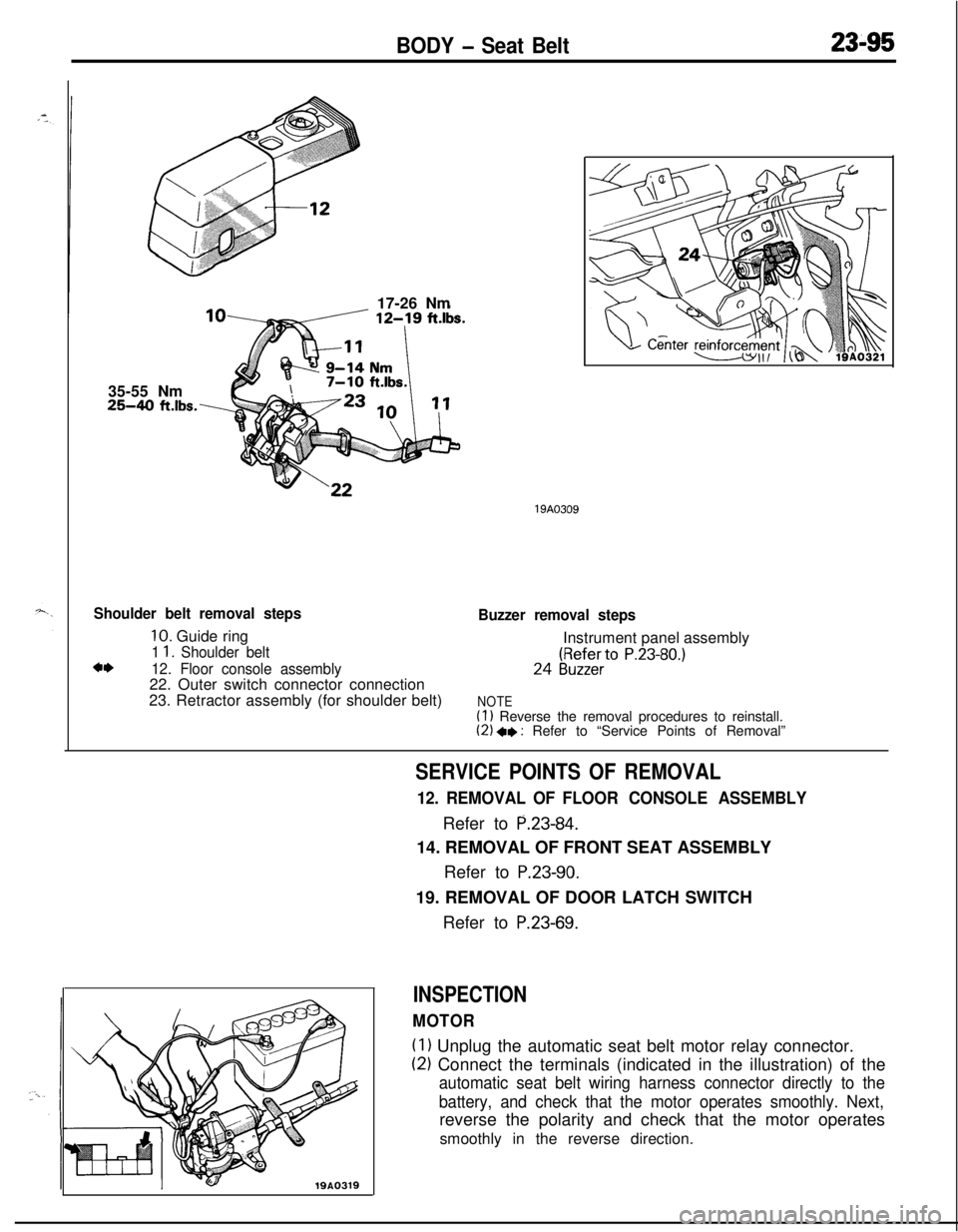
BODY - Seat Belt23-9535-55 Nm
25-40 ft.lbs.\17-26 Nm
Shoulder belt removal steps
10. Guide ring
1 1. Shoulder beltc*12. Floor console assembly22. Outer switch connector connection
23. Retractor assembly (for shoulder belt)
19A0309
Buzzer removal stepsInstrument panel assembly24
(gy;ZfieerrtO P.23-80.)
NOTE(1) Reverse the removal procedures to reinstall.(2) +e : Refer to “Service Points of Removal”
19A0319
SERVICE POINTS OF REMOVAL
12. REMOVAL OF FLOOR CONSOLE ASSEMBLYRefer to
P.23-84.14. REMOVAL OF FRONT SEAT ASSEMBLY
Refer to
P.23-90.19. REMOVAL OF DOOR LATCH SWITCH
Refer to
P.23-69.
INSPECTION
MOTOR
(1) Unplug the automatic seat belt motor relay connector.
(2) Connect the terminals (indicated in the illustration) of the
automatic seat belt wiring harness connector directly to the
battery, and check that the motor operates smoothly. Next,reverse the polarity and check that the motor operates
smoothly in the reverse direction.