check engine MITSUBISHI ECLIPSE 1991 Manual PDF
[x] Cancel search | Manufacturer: MITSUBISHI, Model Year: 1991, Model line: ECLIPSE, Model: MITSUBISHI ECLIPSE 1991Pages: 1216, PDF Size: 67.42 MB
Page 353 of 1216
ENGINE <1.8L Engine> -Crankshaft, Flywheel and Drive PlateS-69
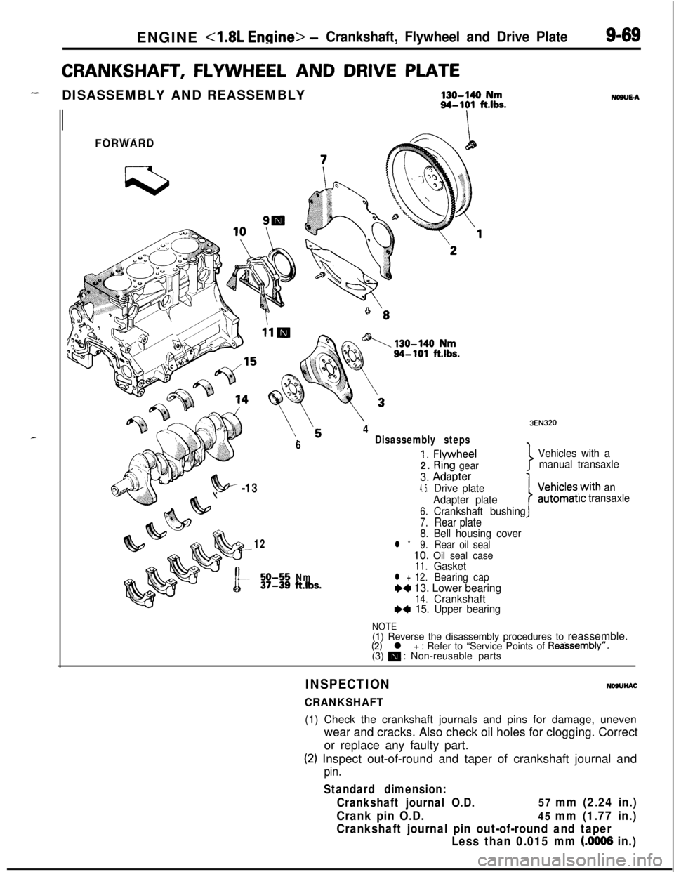
CRANKSHAFT, FLYWHEEL AND DRIVE PLATE
-DISASSEMBLY AND REASSEMBLY130-140 Nm94-101 fths.
II
FORWARD
6
4Disassembly steps
1. Flvwheel2.
Riâng gear
3.
Adaoter
NONE-A
3EN320
Vehicles with a
manual transaxle
7
?!w -134. 5.Drive plate
Adapter plate
6.Crankshaft bushing
7.Rear plate8. Bell housing cover12l *9.Rear oil seal10. Oil seal case11.Gasket50-55Nm12.37-39ft.lbs.l +BearingcapW 13. Lower bearing14.CrankshaftI)* 15. Upper bearing
IVehicles.with an
automatrctransaxle
NOTE(1) Reverse the disassembly procedures to reassemble.
(2) l + : Refer to âService Points of Reassemblyâ.
(3) m : Non-reusable parts
INSPECTION
CRANKSHAFT
NOSUHAC(1) Check the crankshaft journals and pins for damage, uneven
wear and cracks. Also check oil holes for clogging. Correct
or replace any faulty part.
(2) Inspect out-of-round and taper of crankshaft journal and
pin.
Standard dimension:
Crankshaft journal O.D.
57 mm (2.24 in.)
Crank pin O.D.
45 mm (1.77 in.)
Crankshaft journal pin out-of-round and taper
Less than 0.015 mm
(.0006 in.)
Page 354 of 1216
ENGINE <1.8L Engine> -Crankshaft, Flywheel and Drive Plate
3EN055
6EN043
1 EN067
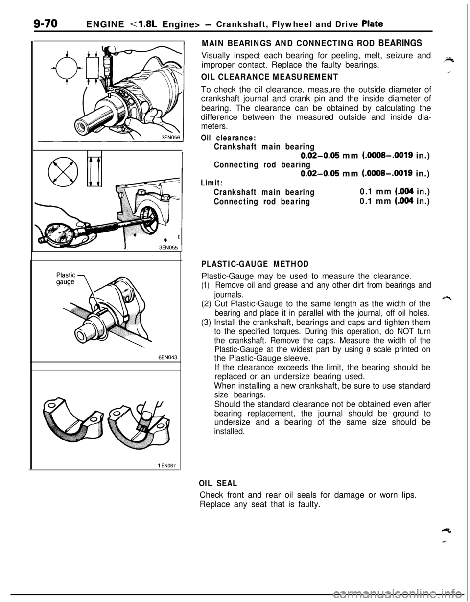
MAIN BEARINGS AND CONNECTING ROD BEARINGSVisually inspect each bearing for peeling, melt, seizure and
improper contact. Replace the faulty bearings.
OIL CLEARANCE MEASUREMENTTo check the oil clearance, measure the outside diameter of
crankshaft journal and crank pin and the inside diameter of
bearing. The clearance can be obtained by calculating the
difference between the measured outside and inside dia-
meters.
Oil clearance:
Crankshaft main bearing
0.02-0.05 mm (.OOOS-.0019 in.)
Connecting rod bearing
0.02-0.05 mm (.OOOS-.0019 in.)
Limit:
Crankshaft main bearing0.1 mm (.004 in.)
Connecting rod bearing0.1 mm (.004 in.)
PLASTIC-GAUGE METHODPlastic-Gauge may be used to measure the clearance.
(1)Remove oil and grease and any other dirt from bearings and
journals.(2) Cut Plastic-Gauge to the same length as the width of the
bearing and place it in parallel with the journal, off oil holes.(3) Install the crankshaft, bearings and caps and tighten them
to the specified torques. During this operation, do NOT turn
the crankshaft. Remove the caps. Measure the width of the
Plastic-Gauge at the widest part by using
a scale printed onthe Plastic-Gauge sleeve.
If the clearance exceeds the limit, the bearing should be
replaced or an undersize bearing used.
When installing a new crankshaft, be sure to use standard
size bearings.Should the standard clearance not be obtained even after
bearing replacement, the journal should be ground to
undersize and a bearing of the same size should be
installed.
OIL SEALCheck front and rear oil seals for damage or worn lips.
Replace any seat that is faulty.
Page 355 of 1216
ENGINE - Crankshaft, Flwvheel and Drive Plate9-71
3EN30âlrrow mark toward
cap No,
I
RING GEAR (Engine with a manual transaxle)Check the ring gear for worn, damaged or broken teeth.
Replace the ring gear if teeth are faulty, and also check the
starter motor pinion.
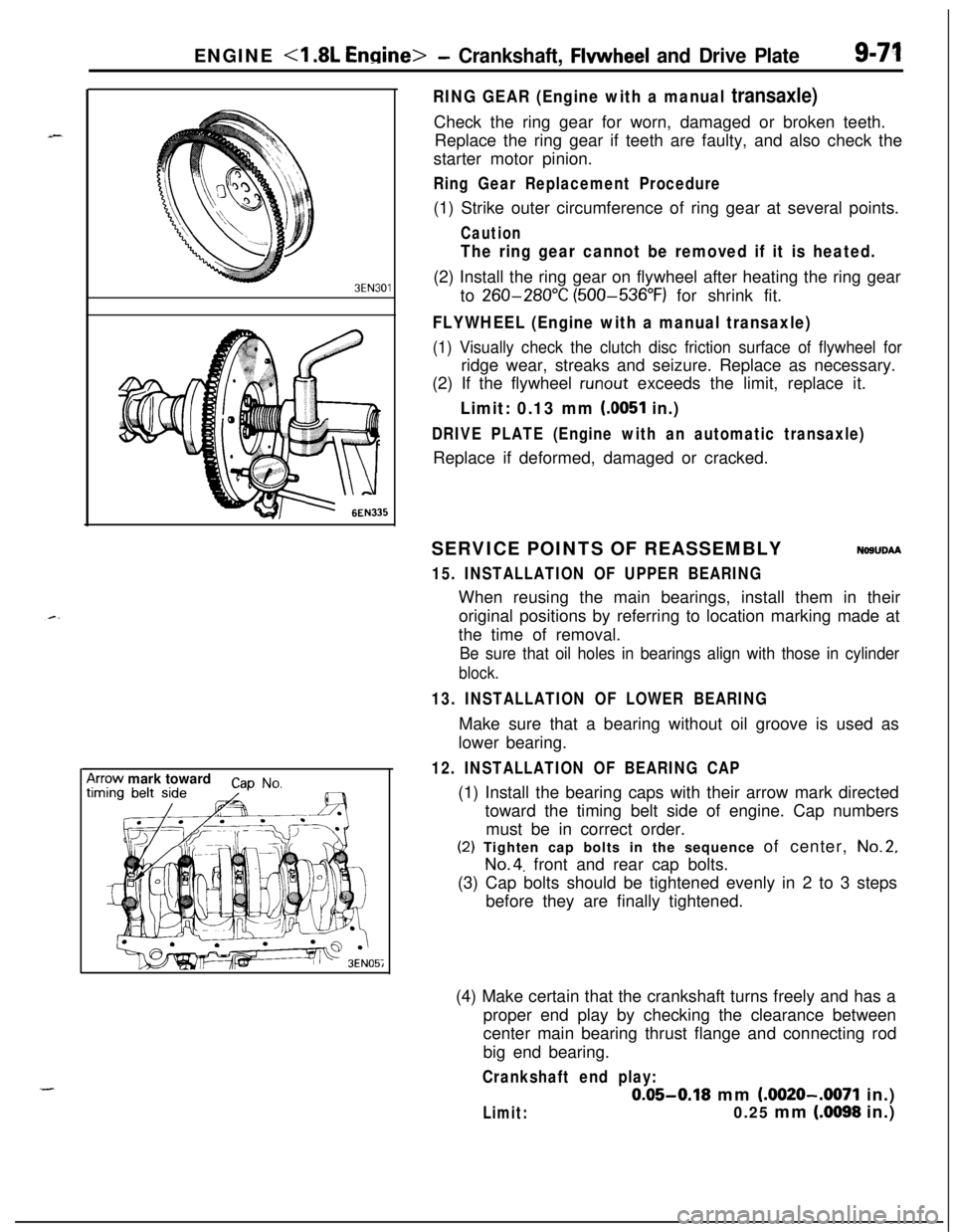
Ring Gear Replacement Procedure(1) Strike outer circumference of ring gear at several points.
Caution
The ring gear cannot be removed if it is heated.(2) Install the ring gear on flywheel after heating the ring gear
to
260-280°C (500-536°F) for shrink fit.
FLYWHEEL (Engine with a manual transaxle)
(1) Visually check the clutch disc friction surface of flywheel forridge wear, streaks and seizure. Replace as necessary.
(2) If the flywheel
runout exceeds the limit, replace it.
Limit: 0.13 mm (0051 in.)
DRIVE PLATE (Engine with an automatic transaxle)Replace if deformed, damaged or cracked.
SERVICE POINTS OF REASSEMBLY
NOSUDAA
15. INSTALLATION OF UPPER BEARINGWhen reusing the main bearings, install them in their
original positions by referring to location marking made at
the time of removal.
Be sure that oil holes in bearings align with those in cylinder
block.
13. INSTALLATION OF LOWER BEARINGMake sure that a bearing without oil groove is used as
lower bearing.
12. INSTALLATION OF BEARING CAP(1) Install the bearing caps with their arrow mark directed
toward the timing belt side of engine. Cap numbers
must be in correct order.(2) Tighten cap bolts in the sequence of center,
No.2,
No.4. front and rear cap bolts.
(3) Cap bolts should be tightened evenly in 2 to 3 steps
before they are finally tightened.
(4) Make certain that the crankshaft turns freely and has a
proper end play by checking the clearance between
center main bearing thrust flange and connecting rod
big end bearing.
Crankshaft end play:
0.05-0.18 mm (.0020-.0071 in.)
Limit:0.25 mm (.0098 in.)
Page 356 of 1216
9-72ENGINE <1.8L Engine> -Crankshaft, Flywheel and Drive Plate/Cylinder Block
PressOil seal
I
MD99801 1
/
Oil seal case1 EN06L
CYLINDER BLOCK
i//
199.
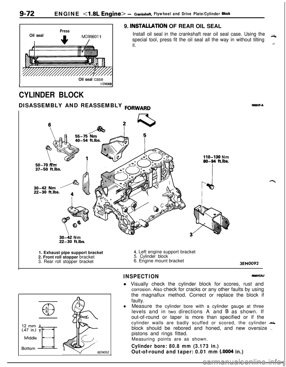
INSTALLATlON OF REAR OIL SEAL
Install oil seal in the crankshaft rear oil seal case. Using the
special tool, press fit the oil seal all the way in without tiltingiii
it.DISASSEMBLY AND REASSEMBLY
FORWARD
50-70 Nm37-50 ft.lbs.
30-42 Nm22-30 ft.lbs.
NDBVF-A
110-130 Nm80-94 ft.lbs.1. Exhaust pipe support bracket
2. Front roll stopper bracket
3. Rear roll stopper bracket
4. Left engine support bracket5. Cylinder block6. Engine mount bracket
3EN0092
INSPECTIONl Visually check the cylinder block for scores, rust and
corrosion. Also check for cracks or any other faults by using
the magnaflux method. Correct or replace the block if
faulty.
lMeasure the cylinder bore with a cylinder gauge at three
levels and in two directions A and
B as shown. If
out-of-round or taper is more than specified or if the
cylinder walls are badly scuffed or scored, the cylinder
&block should be rebored and honed, and new oversize
_pistons and rings fitted.
Measuring points are as shown.
Cylinder bore: 80.8 mm (3.173 in.)
Out-of-round and taper: 0.01 mm (.0004 in.)
Page 357 of 1216
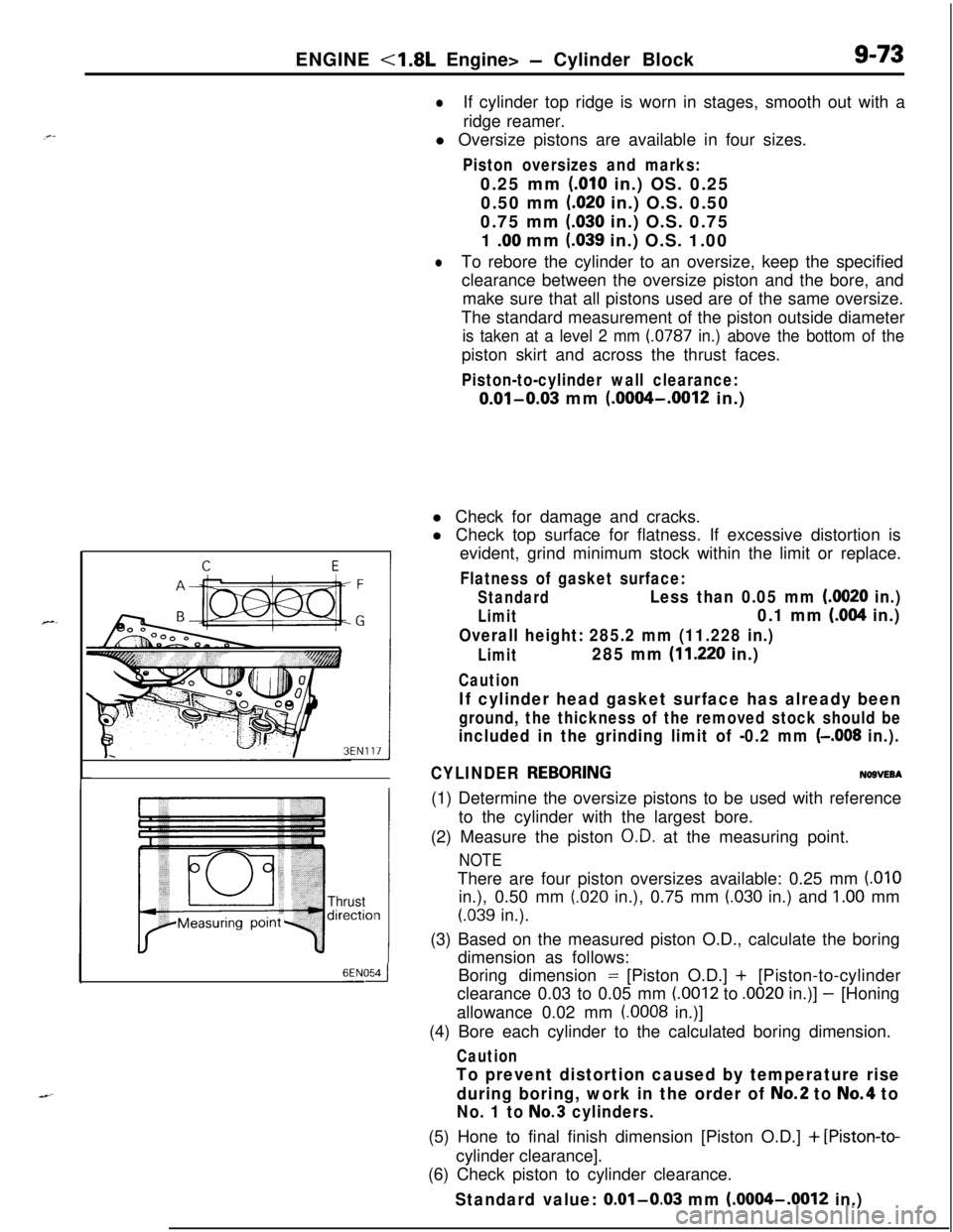
ENGINE <1.8L Engine> - Cylinder Block9-73
lIf cylinder top ridge is worn in stages, smooth out with a
ridge reamer.
l Oversize pistons are available in four sizes.
Piston oversizes and marks:0.25 mm
(.OlO in.) OS. 0.25
0.50 mm
(.020 in.) O.S. 0.50
0.75 mm
(.030 in.) O.S. 0.75
1
.OO mm (.039 in.) O.S. 1.00
lTo rebore the cylinder to an oversize, keep the specified
clearance between the oversize piston and the bore, and
make sure that all pistons used are of the same oversize.
The standard measurement of the piston outside diameter
is taken at a level 2 mm (0787 in.) above the bottom of thepiston skirt and across the thrust faces.
Piston-to-cylinder wall clearance:
0.01-0.03 mm (.0004-.0012 in.)
Thrustdirectiol
6ENOdl Check for damage and cracks.
l Check top surface for flatness. If excessive distortion is
evident, grind minimum stock within the limit or replace.
Flatness of gasket surface:
StandardLess than 0.05 mm (0020 in.)
Limit0.1 mm (.004 in.)
Overall height: 285.2 mm (11.228 in.)
Limit285 mm (11.220 in.)
Caution
If cylinder head gasket surface has already been
ground, the thickness of the removed stock should be
included in the grinding limit of -0.2 mm (-.008 in.).
CYLINDER
REBORINGNOBVEBA(1) Determine the oversize pistons to be used with reference
to the cylinder with the largest bore.
(2) Measure the piston
O.D. at the measuring point.
NOTEThere are four piston oversizes available: 0.25 mm
(.OlOin.), 0.50 mm
(.020 in.), 0.75 mm (.030 in.) and 1.00 mm
(.039 in.).
(3) Based on the measured piston O.D., calculate the boring
dimension as follows:
Boring dimension = [Piston O.D.] + [Piston-to-cylinder
clearance 0.03 to 0.05 mm
(.0012 to .0020 in.)] - [Honing
allowance 0.02 mm
(.0008 in.)]
(4) Bore each cylinder to the calculated boring dimension.
Caution
To prevent distortion caused by temperature rise
during boring, work in the order of
No.2 to No.4 to
No. 1 to No.3 cylinders.(5) Hone to final finish dimension [Piston O.D.]
+ [Piston-to-cylinder clearance].
(6) Check piston to cylinder clearance.
Standard value: 0.01-0.03 mm (.0004-.0012 in.)
Page 358 of 1216
9-74ENGINE <2.0L DOHC Engine>- Service Adjustment Procedures
ENGINE <2.0L DOHC Engine>
SERVICE ADJUSTMENT PROCEDURES pi
CHECKING COMPRESSION PRESSURENOSFFAH(1) Before checking compression, ensure that engine oil, the
starter motor, and battery are all in good condition.
(2) Start the engine and wait until engine coolant temperature
has risen to
85-95°C (185-205°F).
(3) Stop the engine and pull the spark plug cables.
(4) Remove the spark plugs.
(5) Crank the engine
to. remove any foreign objects in the
cylinders.
Caution
Cover the spark plug holes with shop towel, etc., in
order to keep expelled foreign objects from flying out,and keep away from the holes. When measuring
compression with water, oil, or fuel having entered the
cylinder through a crack, etc., these will come flying
out of the spark plug hole hot and fast, so be sure to
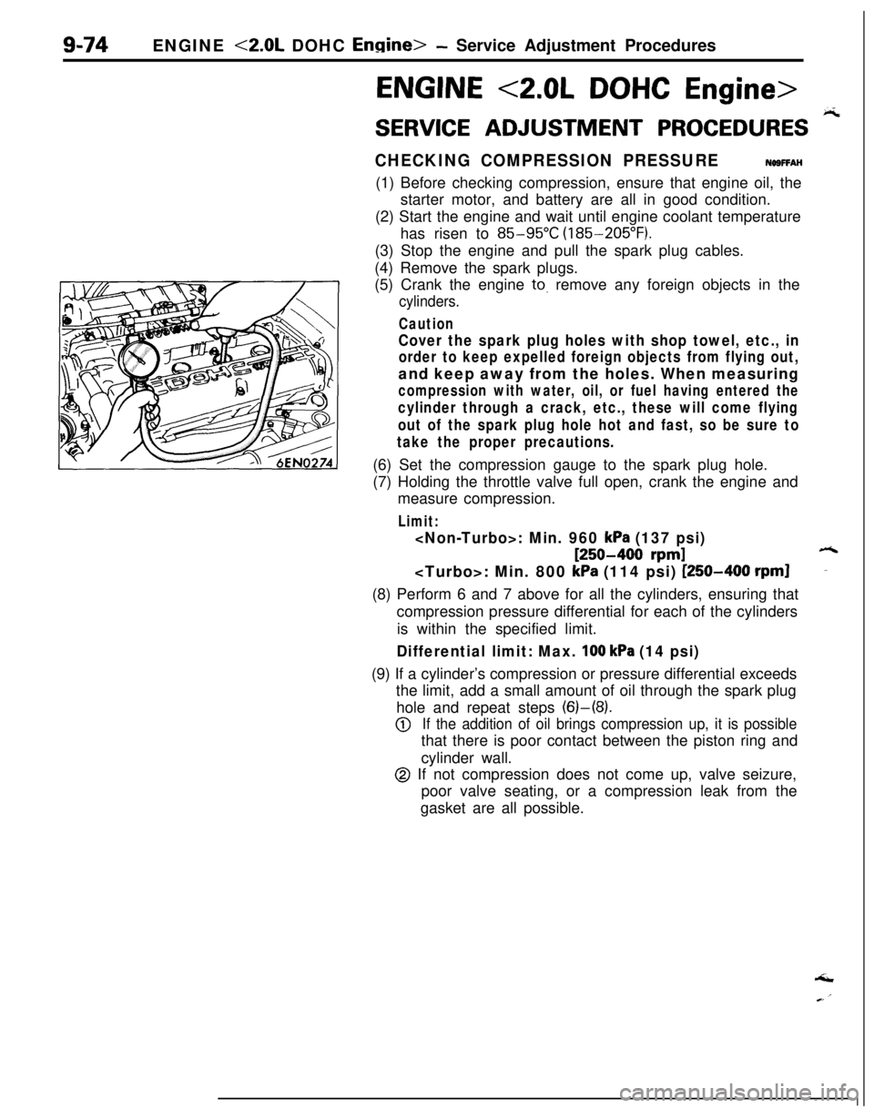
take the proper precautions.(6) Set the compression gauge to the spark plug hole.
(7) Holding the throttle valve full open, crank the engine and
measure compression.
Limit:
[250-400 rpm]6
kPa (114 psi) [250-400 rpml-(8) Perform 6 and 7 above for all the cylinders, ensuring that
compression pressure differential for each of the cylinders
is within the specified limit.
Differential limit: Max. 100 kPa (14 psi)(9) If a cylinderâs compression or pressure differential exceeds
the limit, add a small amount of oil through the spark plug
hole and repeat steps (6)-(8).
@If the addition of oil brings compression up, it is possiblethat there is poor contact between the piston ring and
cylinder wall.
@ If not compression does not come up, valve seizure,
poor valve seating, or a compression leak from the
gasket are all possible.âI
Page 359 of 1216
_-
a--ENGINE
<2.0L DOHC Engine> -Service Adjustment Procedures9-75
JMANIFOLD VACUUM INSPECTION
NO9FNAO(1) Before inspection and adjustment, put the vehicle into the
following state.
l Engine coolant temperature:
85-g5âC (185-205°F)
l Lights, electric, cooling fan, and accessories: OFF
lTransaxle: Neutral (N or
P for vehicles with an automa-
tic transaxle)
l Steering wheel: Neutral position
(2) Check that the idling revolution speed is normal.
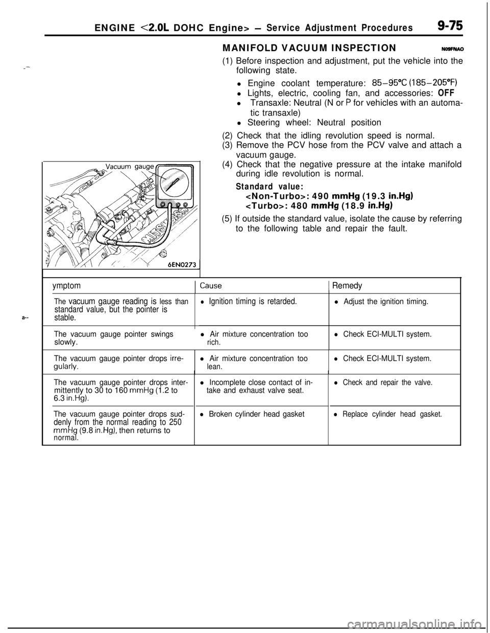
(3) Remove the PCV hose from the PCV valve and attach a
vacuum gauge.
(4) Check that the negative pressure at the intake manifold
during idle revolution is normal.
Standard value:
mmHg (19.3 in.Hg)
mmHg (18.9 in.Hg)(5) If outside the standard value, isolate the cause by referring
to the following table and repair the fault.
ymptomICause1 Remedy
The vacuum gauge reading is less than
standard value, but the pointer is
stable.
The vacuum gauge pointer swingsslowly.
l Ignition timing is retarded.
l Air mixture concentration too
rich.
l Adjust the ignition timing.
l Check ECI-MULTI system.
The vacuum gauge pointer drops
irre-gularly.l Air mixture concentration too
lean.
l Check ECI-MULTI system.
The vacuum gauge pointer drops inter-mittently to 30 to 160
mmHg (1.2 to
6.3 in.Hg).
The vacuum gauge pointer drops sud-
denly from the normal reading to 250
mmHg (9.8 in.Hg), then returns tonormal.
l Incomplete close contact of in-
take and exhaust valve seat.
l Broken cylinder head gasket
l Check and repair the valve.
l Replace cylinder head gasket.
Page 360 of 1216
9-76ENGINE <2.0L DOHC Engine> -Service Adjustment Procedures
LASH ADJUSTERS CHECKNOBFEABalIf an abnormal noise is heard from the lash adjusters check as
follows.
(1) After warming up the engine, stop it.
(2) While installed to the cylinder head, press the part of rockerarm that contacts the lash adjuster. The part pressed will
feel very hard if the lash adjuster condition is normal.
(3) If, when pressed, it easily descends all the way downward,
replace the lash adjuster.
(4) If there is a spongy feeling when pressed, air is probably
mixed in, and so the cause should be investigated. The
cause is probably an insufficient amount of engine oil, or
damage to the oil screen and/or screen gasket.
(5) After finding the cause and taking the appropriate step
(adding oil or repair), warm up the engine and drive at low
speed for a short time. Then, after stopping the engine andwaiting a few minutes, drive again at low speed. Repeat
this procedure a few times to bleed out the air from the oil.
Page 361 of 1216
ENGINE <2.0L DOHC Engine> - Engine Mounting
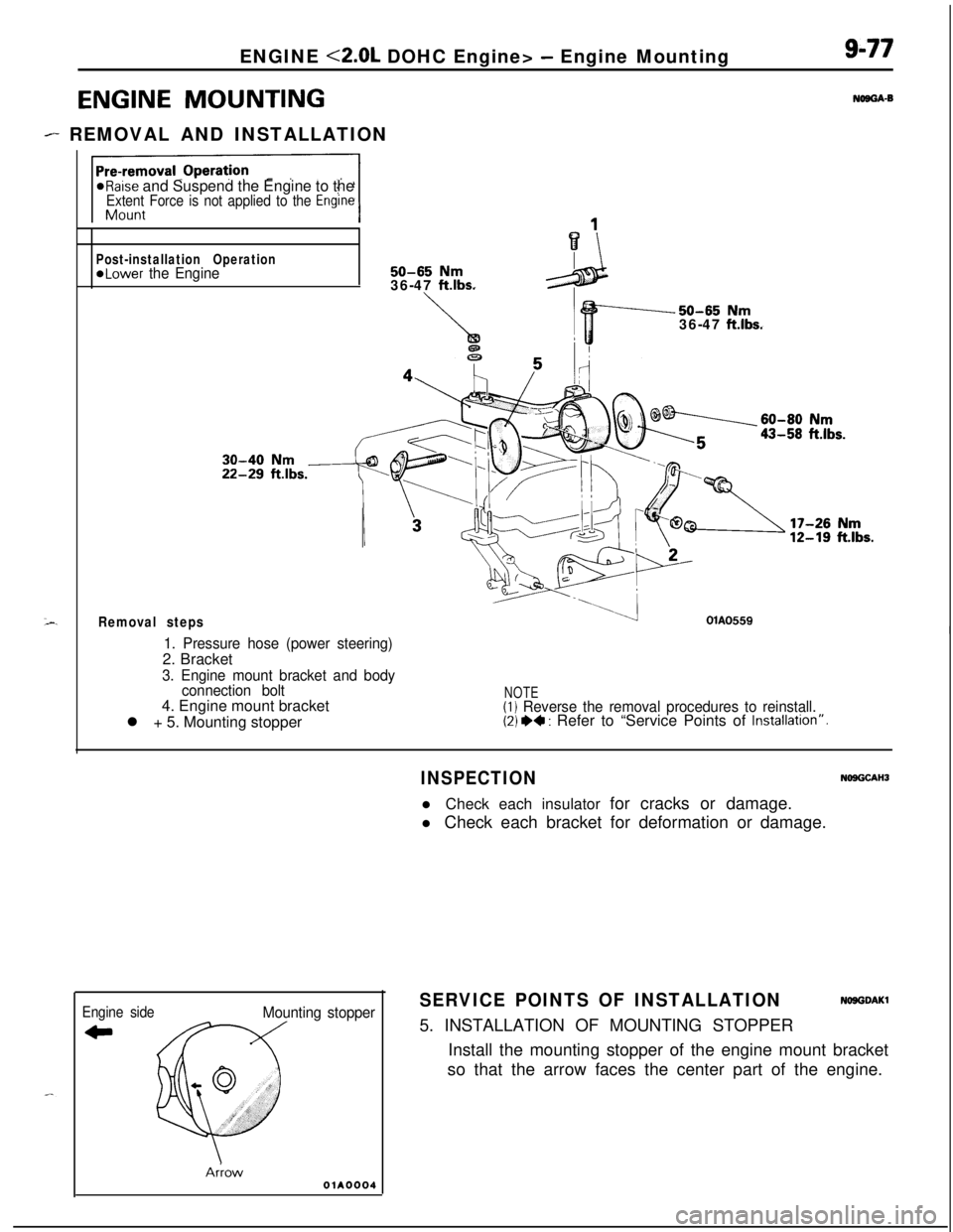
ENGINE MOUNTING
- REMOVAL AND INSTALLATION
9-77
NOBGA-B
*Raise and Suspend the Engine to theExtent Force is not applied to the Engine
Post-installation Operation@Lower the Engine50-65 Nm36-47 ftlbs.
Removal steps
50-65 Nm36-47 ftlbs.
OlAO559I1. Pressure hose (power steering)2. Bracket
3. Engine mount bracket and body
connection bolt4. Engine mount bracket
l + 5. Mounting stopper
NOTE(1) Reverse the removal procedures to reinstall.(2) *+ : Refer to âService Points of Installatronâ.
Engine side
CI
Mounting stopper
AnowOlA0004
INSPECTIONNOSGCAHJl Check each insulator for cracks or damage.
l Check each bracket for deformation or damage.
SERVICE POINTS OF INSTALLATIONNOSGDAKl5. INSTALLATION OF MOUNTING STOPPER
Install the mounting stopper of the engine mount bracket
so that the arrow faces the center part of the engine.
Page 362 of 1216
9-78ENGINE <2.0L DOHC Engine> - Transaxle Mounting
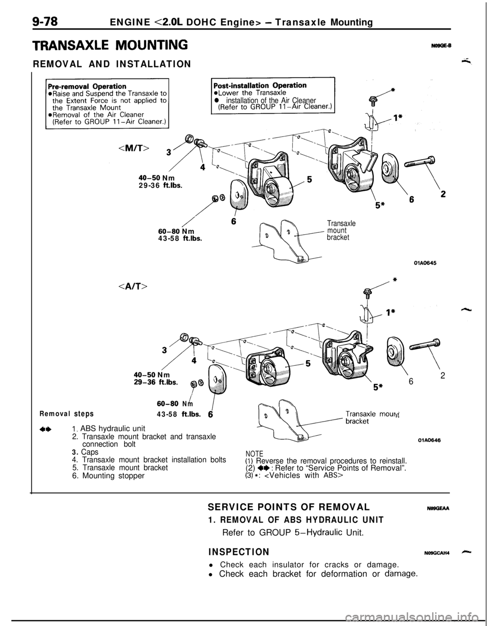
TRANSAXLE MOUNTING
REMOVAL AND INSTALLATION
No9GE-6
l installation of the Air Cleaner
40-50 Nm
29-36 ftlbs.
/ 660-80 Nm
43-58 ftlbs.
Transaxle
mount
bracketOlA0645
40-50 Nm
*
6
625â
/60-80Nm-f-h
Removalsteps43-58ftlbs.61t
4*I. ABS hydraulic unit
2. Transaxle mount bracket and transaxle
connection bolt
3. Caps
4. Transaxle mount bracket installation bolts
5. Transaxle mount bracket6. Mounting stopperNOTE(I) Reverse the removal procedures to reinstall.(2) +* : Refer to âService Points of Removalâ.(3) *:
1. REMOVAL OF ABS HYDRAULIC UNITRefer to GROUP
5-Hydraulic Unit.
NO9GEAA
INSPECTIONNOSGCAH4l Check each insulator for cracks or damage.
l Check each bracket for deformation or
dsmage.