check engine MITSUBISHI ECLIPSE 1991 Workshop Manual
[x] Cancel search | Manufacturer: MITSUBISHI, Model Year: 1991, Model line: ECLIPSE, Model: MITSUBISHI ECLIPSE 1991Pages: 1216, PDF Size: 67.42 MB
Page 312 of 1216
9-28ENGINE <1.8L Engine> - Engine Mounting
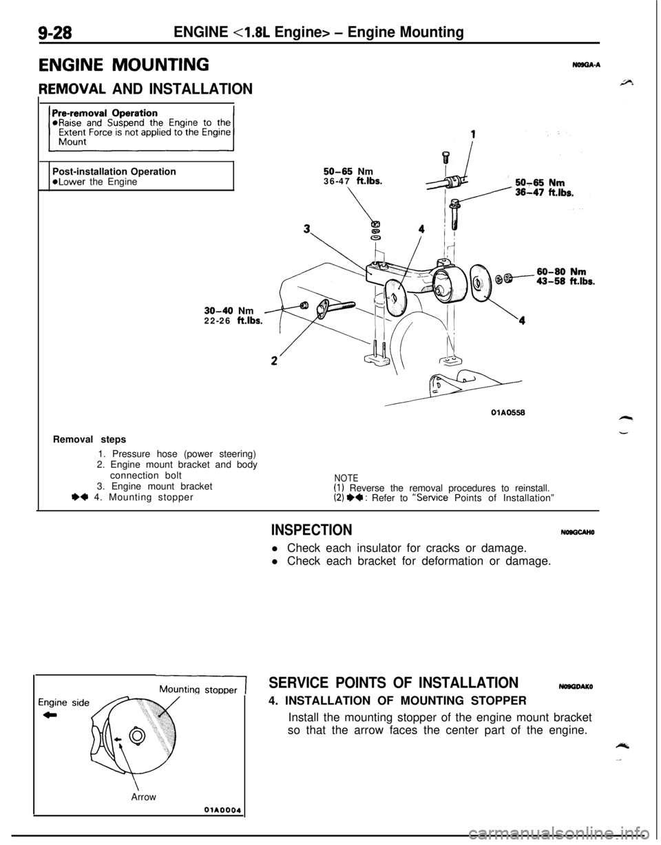
ENGINE MOUNTING
IEMOVAL AND INSTALLATION
NOB8A-APost-installation Operation
50-65 Nm*Lower the Engine36-47 ft.lbs.
30-40 Nm
22-26 ft.lbs.Removal steps
1. Pressure hose (power steering)
2. Engine mount bracket and body
connection bolt
3. Engine mount bracket
e+ 4. Mounting stopper
NOTE(1) Reverse the removal procedures to reinstall.(2) +* : Refer to “Service Points of Installation”
INSPECTIONNOOQCANOl Check each insulator for cracks or damage.
l Check each bracket for deformation or damage.
MountingSERVICE POINTS OF INSTALLATION4. INSTALLATION OF MOUNTING STOPPER
Install the mounting stopper of the engine mount bracket
so that the arrow faces the center part of the engine.
Arrow
OiA0004
Page 313 of 1216
ENGINE <1.8L Engine> - Transaxle Mounting
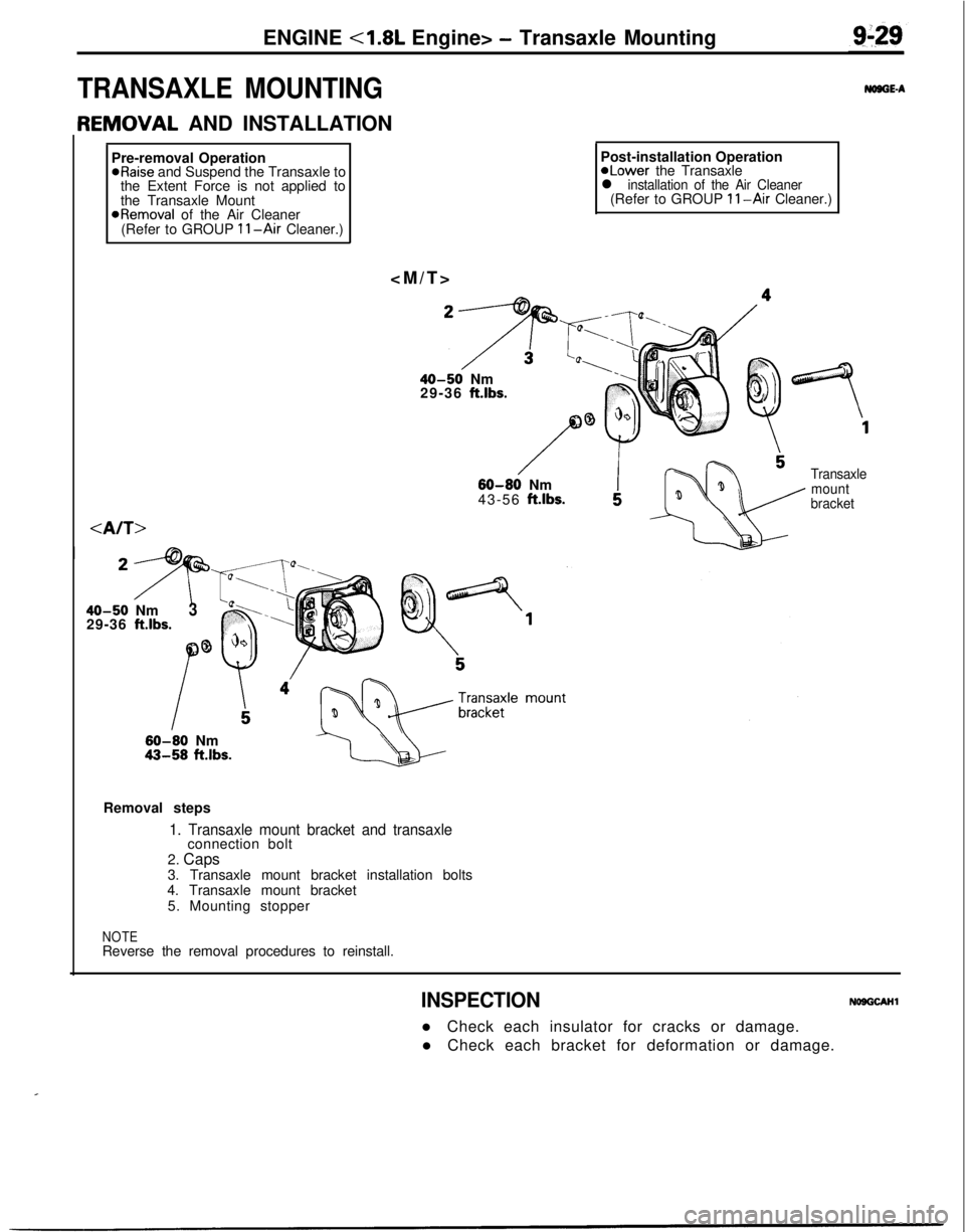
TRANSAXLE MOUNTING
IEMOVAL AND INSTALLATION
Pre-removal Operation*Raise and Suspend the Transaxle to
the Extent Force is not applied to
the Transaxle Mount
@Removal of the Air Cleaner
(Refer to GROUP 11-Air Cleaner.)
NOSGE-APost-installation OperationaLower the Transaxle
l installation of the Air Cleaner(Refer to GROUP II-Air Cleaner.)
40-50 Nm
29-36 ft.lbs.
/W-60 Nm
43-56 ft.lbs.
Transaxle
mount
bracket
40-50 Nm
29-36 ft.lbs.3
60-80 Nm43-58 ft.lbs.Removal steps
1. Transaxle mount bracket and transaxleconnection bolt
2. Caps
3. Transaxle mount bracket installation bolts
4. Transaxle mount bracket
5. Mounting stopper
NOTEReverse the removal procedures to reinstall.
INSPECTIONNOOGCAHll Check each insulator for cracks or damage.
l Check each bracket for deformation or damage.
.I
Page 314 of 1216
50-65 Nm*36-47 ft.lbs.*
9-30ENGINE - Engine Roll Stopper
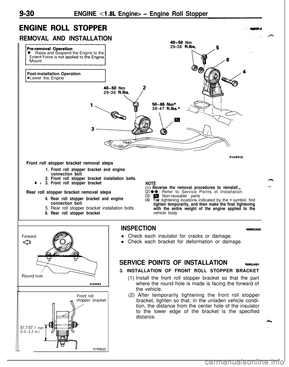
ENGINE ROLL STOPPER
REMOVAL AND INSTALLATION40-50 Nm
29-36 ft.lbs.
l Raise and Suspend the Engine to the
Post-installation Operation
*Lower the Engine
40-50 Nm
29-36 ft.lbs.\/*01A0012
Front roll stopper bracket removal steps1. Front roll stopper bracket and engine
connection bolt
2. Front roll stopper bracket installation bolts
l +3. Front roll stopper bracket
Rear roll stopper bracket removal steps4. Rear roll stopper bracket and engine
connection bolt
5. Rear roll stopper bracket installation bolts6. Rear roll stopper bracketNOTE
(1) Reverse the removal procedures to reinstall.,,
I;/ I)+ : Refer to Service Points of Installation
Non-reusable parts
(4)Por tightening locations indicated by the * symbol, first
tighten temporarily, and then make the final tightening
with the entire weight of the engine applied to the
vehicle body.
ForwardRound
h&Front roll
51.7-5712.0-2.3.7 mnin.)
bracket
INSPECTIONNosGcAH2l Check each insulator for cracks or damage.
l Check each bracket for deformation or damage.
SERVICE POINTS OF INSTALLATIONNOSGJASl3. INSTALLATION OF FRONT ROLL STOPPER BRACKET
(1)
Install the front roll stopper bracket so that the part
where the round hole is made is facing the forward of
the vehicle.
(2) After temporarily tightening the front roll stopper
bracket, tighten so that, in the unladen vehicle condi-
tion, the distance from the center hole of the insulator
to the lower edge of the bracket is the specified
distance.
Page 317 of 1216
ENGINE <1.8L Engine> - Engine Assemblv9-33
c
!
OlAO582
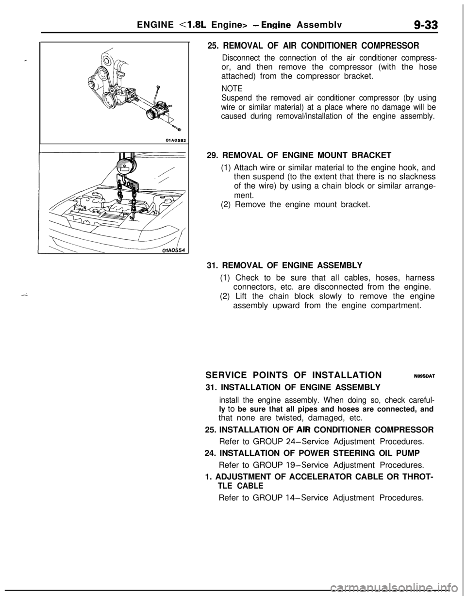
25. REMOVAL OF AIR CONDITIONER COMPRESSOR
Disconnect the connection of the air conditioner compress-or, and then remove the compressor (with the hose
attached) from the compressor bracket.
NOTE
Suspend the removed air conditioner compressor (by using
wire or similar material) at a place where no damage will be
caused during removal/installation of the engine assembly.29. REMOVAL OF ENGINE MOUNT BRACKET
(1) Attach wire or similar material to the engine hook, and
then suspend (to the extent that there is no slackness
of the wire) by using a chain block or similar arrange-
ment.(2) Remove the engine mount bracket.
31. REMOVAL OF ENGINE ASSEMBLY
(1) Check to be sure that all cables, hoses, harness
connectors, etc. are disconnected from the engine.
(2) Lift the chain block slowly to remove the engine
assembly upward from the engine compartment.
SERVICE POINTS OF INSTALLATION
NOSSDAT31. INSTALLATION OF ENGINE ASSEMBLY
install the engine assembly. When doing so, check careful-ly to be sure that all pipes and hoses are connected, and
that none are twisted, damaged, etc.
25. INSTALLATION OF AIR CONDITIONER COMPRESSOR
Refer to GROUP
24-Service Adjustment Procedures.
24. INSTALLATION OF POWER STEERING OIL PUMP
Refer to GROUP
19-Service Adjustment Procedures.
1. ADJUSTMENT OF ACCELERATOR CABLE OR THROT-
TLE CABLERefer to GROUP
14-Service Adjustment Procedures.
Page 318 of 1216
-
c/
(Refer to GROUP O-Maintenance
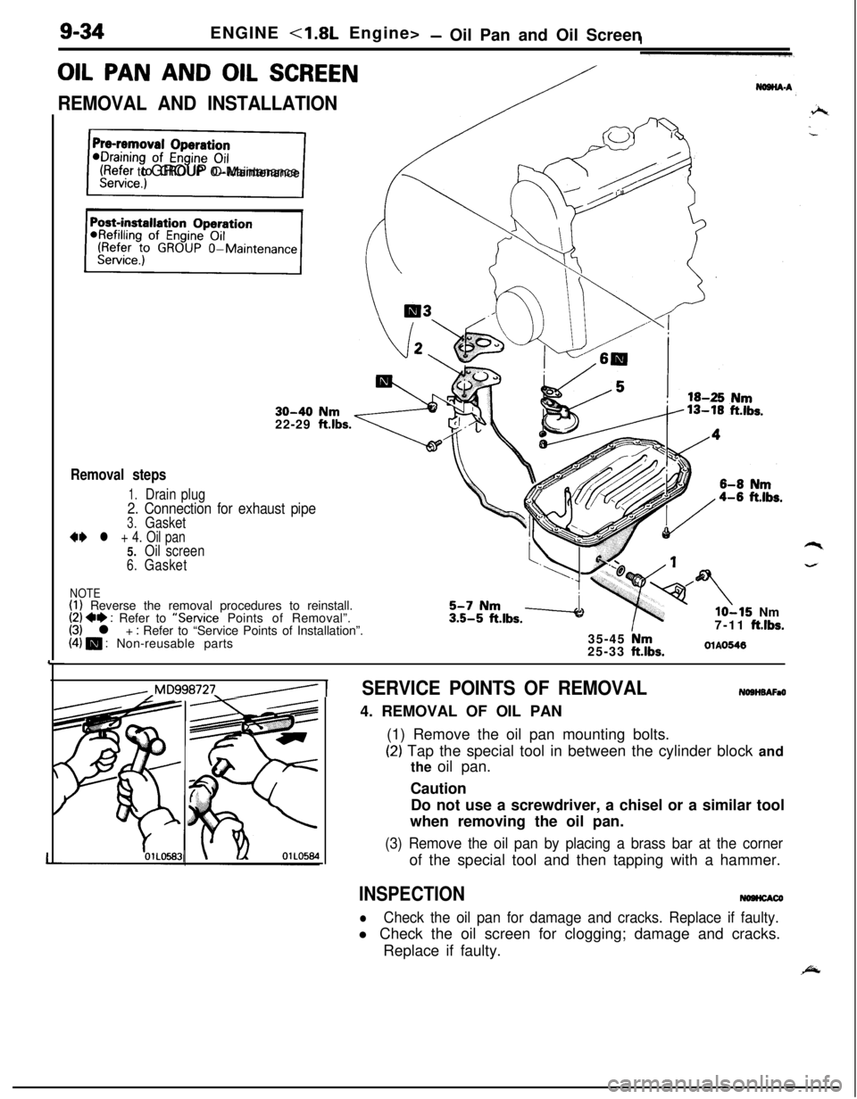
9-34ENGINE <1.8L Engine>- Oil Pan and Oil Screen
OIL PAN AND OIL SCREEN
REMOVAL AND INSTALLATION
30-40 Nm22-29 ftlbs.
Removal steps
1.Drain plug
2. Connection for exhaust pipe
3.Gasket
** l + 4. Oil pan5.Oil screen
6.Gasket
NOTE(1) Reverse the removal procedures to reinstall.(2) +e : Refer to “Service Points of Removal”.(3) l + : Refer to “Service Points of Installation”.(4) m : Non-reusable parts
lo-15 Nm
7-11 ftlbs.35-45 Nm25-33 ftlbs.OlAO546
,,Mq998727_/ 1SERVICE POINTS OF REMOVALNOSHBAFaO4. REMOVAL OF OIL PAN
(1) Remove the oil pan mounting bolts.
(2) Tap the special tool in between the cylinder block and
the oil pan.
Caution
Do not use a screwdriver, a chisel or a similar tool
when removing the oil pan.
(3) Remove the oil pan by placing a brass bar at the cornerof the special tool and then tapping with a hammer.
INSPECTIONNOHCACO
lCheck the oil pan for damage and cracks. Replace if faulty.l Check the oil screen for clogging; damage and cracks.
Replace if faulty.
Page 326 of 1216
g-42ENGINE <1.8L Engine> - Timing Belt
r-04UOO27
,Timing mark
Timing‘mark
lEN0017
c
li
OlA0550SERVICE POINTS OF REMOVAL
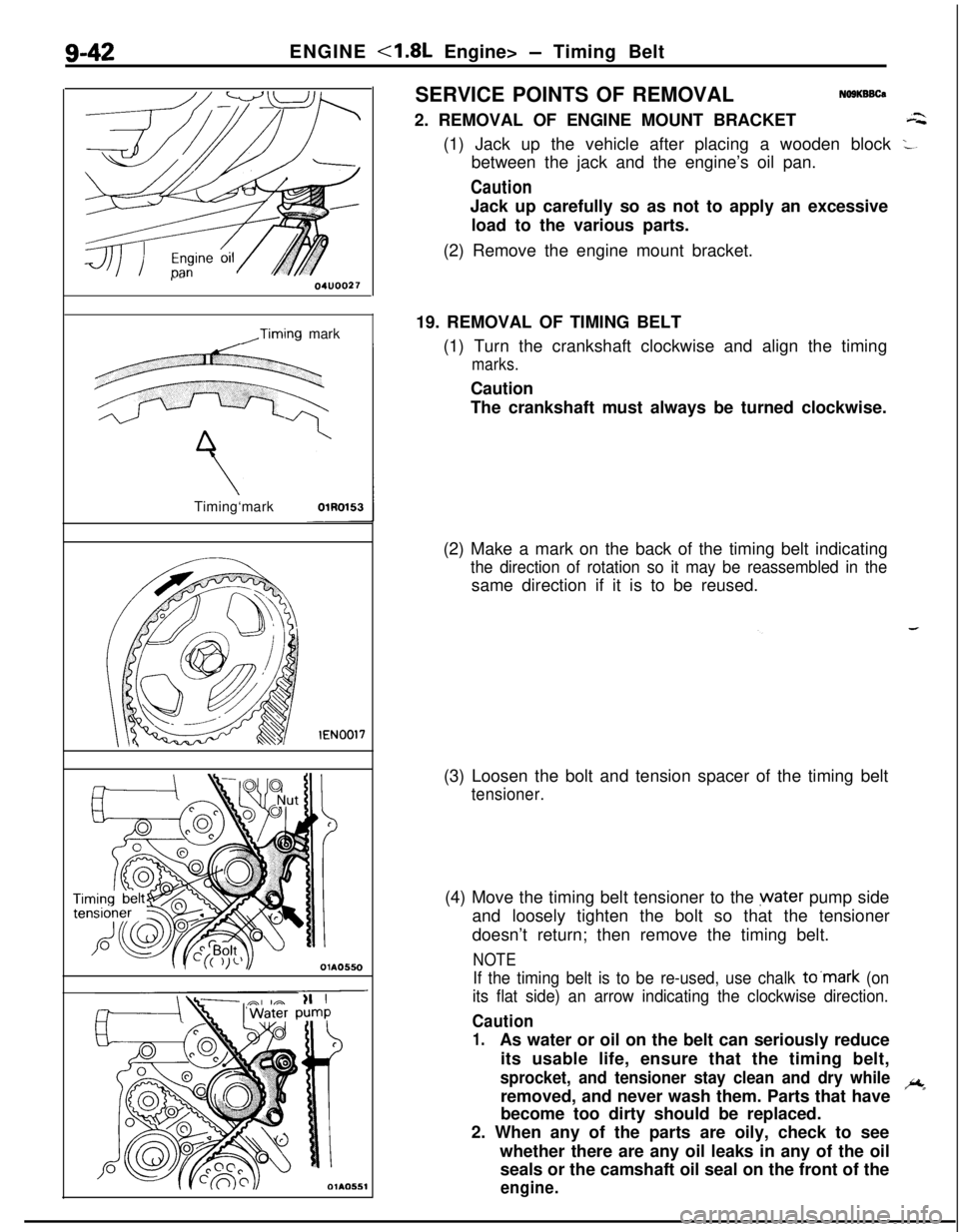
NO9KBBCa2. REMOVAL OF ENGINE MOUNT BRACKET
a(1) Jack up the vehicle after placing a wooden block
:.between the jack and the engine’s oil pan.
CautionJack up carefully so as not to apply an excessive
load to the various parts.
(2) Remove the engine mount bracket.
19. REMOVAL OF TIMING BELT
(1) Turn the crankshaft clockwise and align the timing
marks.Caution
The crankshaft must always be turned clockwise.
(2) Make a mark on the back of the timing belt indicating
the direction of rotation so it may be reassembled in thesame direction if it is to be reused.
(3) Loosen the bolt and tension spacer of the timing belt
tensioner.(4) Move the timing belt tensioner to the water pump side
and loosely tighten the bolt so that the tensioner
doesn’t return; then remove the timing belt.
NOTE
If the timing belt is to be re-used, use chalk to’mark (on
its flat side) an arrow indicating the clockwise direction.
Caution
1.As water or oil on the belt can seriously reduce
its usable life, ensure that the timing belt,
sprocket, and tensioner stay clean and dry whileremoved, and never wash them. Parts that haveic
*become too dirty should be replaced.
2. When any of the parts are oily, check to see
whether there are any oil leaks in any of the oil
seals or the camshaft oil seal on the front of the
engine.
Page 327 of 1216
ENGINE <1.8L Engine> - Timing Belt9-43
-
.
4iJ
:
,000008
7EN206
Crack
7EN207Abnormal wear
(fluffy canvas fiber)7EN2013
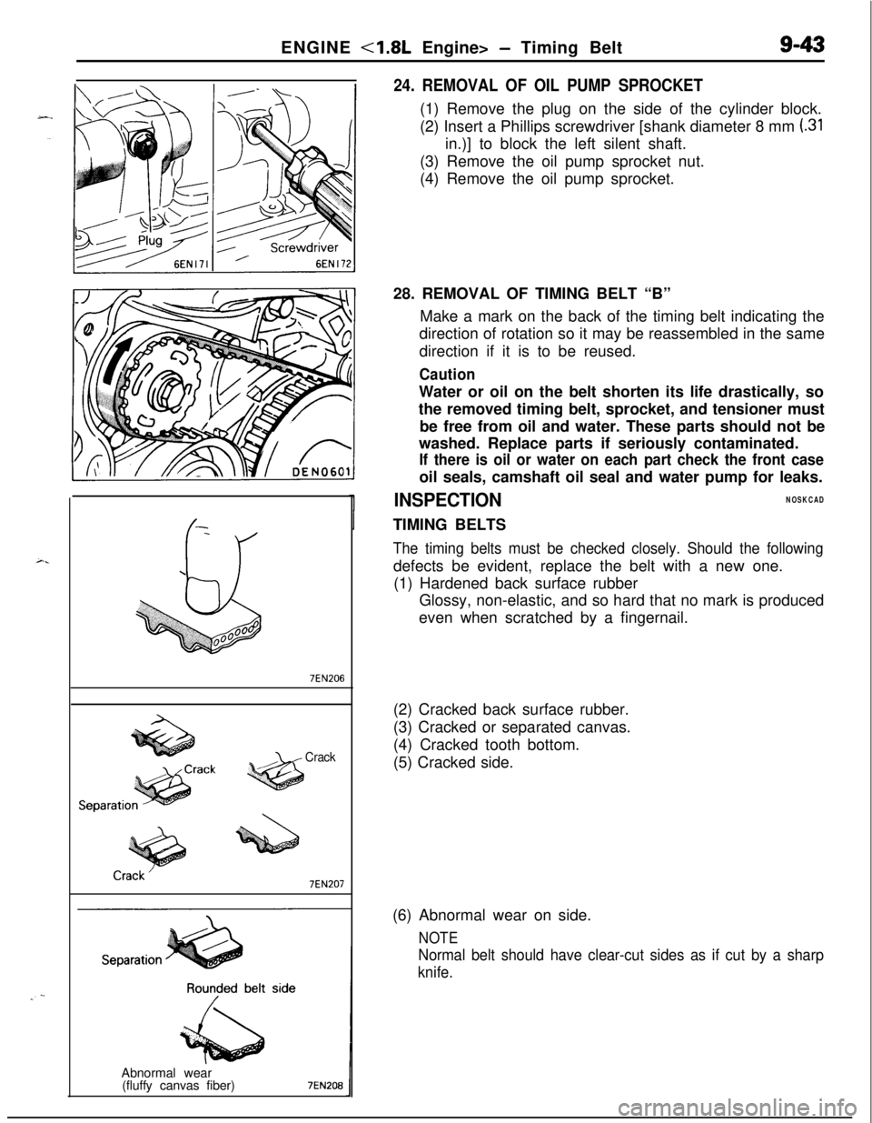
24. REMOVAL OF OIL PUMP SPROCKET(1) Remove the plug on the side of the cylinder block.
(2) Insert a Phillips screwdriver [shank diameter 8 mm
(.31in.)] to block the left silent shaft.
(3) Remove the oil pump sprocket nut.
(4) Remove the oil pump sprocket.
28. REMOVAL OF TIMING BELT “B”
Make a mark on the back of the timing belt indicating the
direction of rotation so it may be reassembled in the same
direction if it is to be reused.
CautionWater or oil on the belt shorten its life drastically, so
the removed timing belt, sprocket, and tensioner must
be free from oil and water. These parts should not be
washed. Replace parts if seriously contaminated.
If there is oil or water on each part check the front caseoil seals, camshaft oil seal and water pump for leaks.
INSPECTIONNOSKCADTIMING BELTS
The timing belts must be checked closely. Should the followingdefects be evident, replace the belt with a new one.
(1) Hardened back surface rubber
Glossy, non-elastic, and so hard that no mark is produced
even when scratched by a fingernail.
(2) Cracked back surface rubber.
(3) Cracked or separated canvas.
(4) Cracked tooth bottom.
(5) Cracked side.
(6) Abnormal wear on side.
NOTE
Normal belt should have clear-cut sides as if cut by a sharp
knife.
Page 328 of 1216
9-44ENGINE <1.8L Engine> - Timing Belt
Rubber
exposedTooth missing and
1 EN0002
Crankshaftsprocket “6
Crankshaft 6EN304
Spacer
Chamfered
6EN009
J
TiGGrnmarkCrankshaft
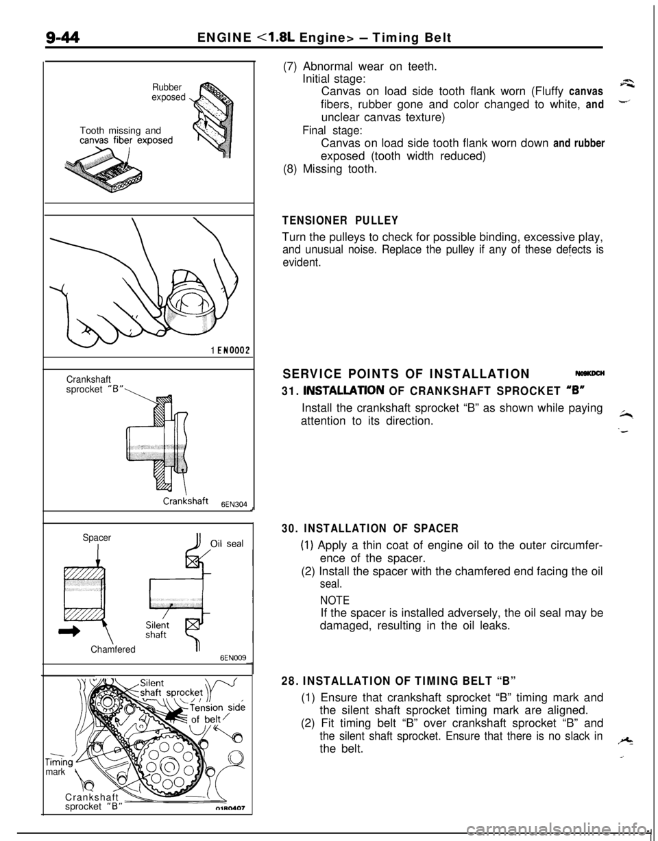
\vsprocket “B”(7) Abnormal wear on teeth.
Initial stage:
Canvas on load side tooth flank worn (Fluffy canvas
afibers, rubber gone and color changed to white, and
-unclear canvas texture)
Final stage:Canvas on load side tooth flank worn down and rubber
exposed (tooth width reduced)
(8) Missing tooth.
TENSIONER PULLEYTurn the pulleys to check for possible binding, excessive play,
and unusual noise. Replace the pulley if any of these defects is
evident.”
SERVICE POINTS OF INSTALLATION
31. INSTALLATlON OF CRANKSHAFT SPROCKET “6”Install the crankshaft sprocket “B” as shown while paying
attention to its direction.
~,
‘d
30. INSTALLATION OF SPACER
(1) Apply a thin coat of engine oil to the outer circumfer-
ence of the spacer.
(2) Install the spacer with the chamfered end facing the oil
seal.
NOTEIf the spacer is installed adversely, the oil seal may be
damaged, resulting in the oil leaks.
28. INSTALLATION OF TIMING BELT “B”(1) Ensure that crankshaft sprocket “B” timing mark and
the silent shaft sprocket timing mark are aligned.
(2) Fit timing belt “B” over crankshaft sprocket “B” and
the silent shaft sprocket. Ensure that there is no slack inthe belt.+
a.
Page 330 of 1216
9-46ENGINE <1.8L Engine> - Timing Belt
Timing mark
Q1hQS4.9
3EN005
OlA0549
c
::
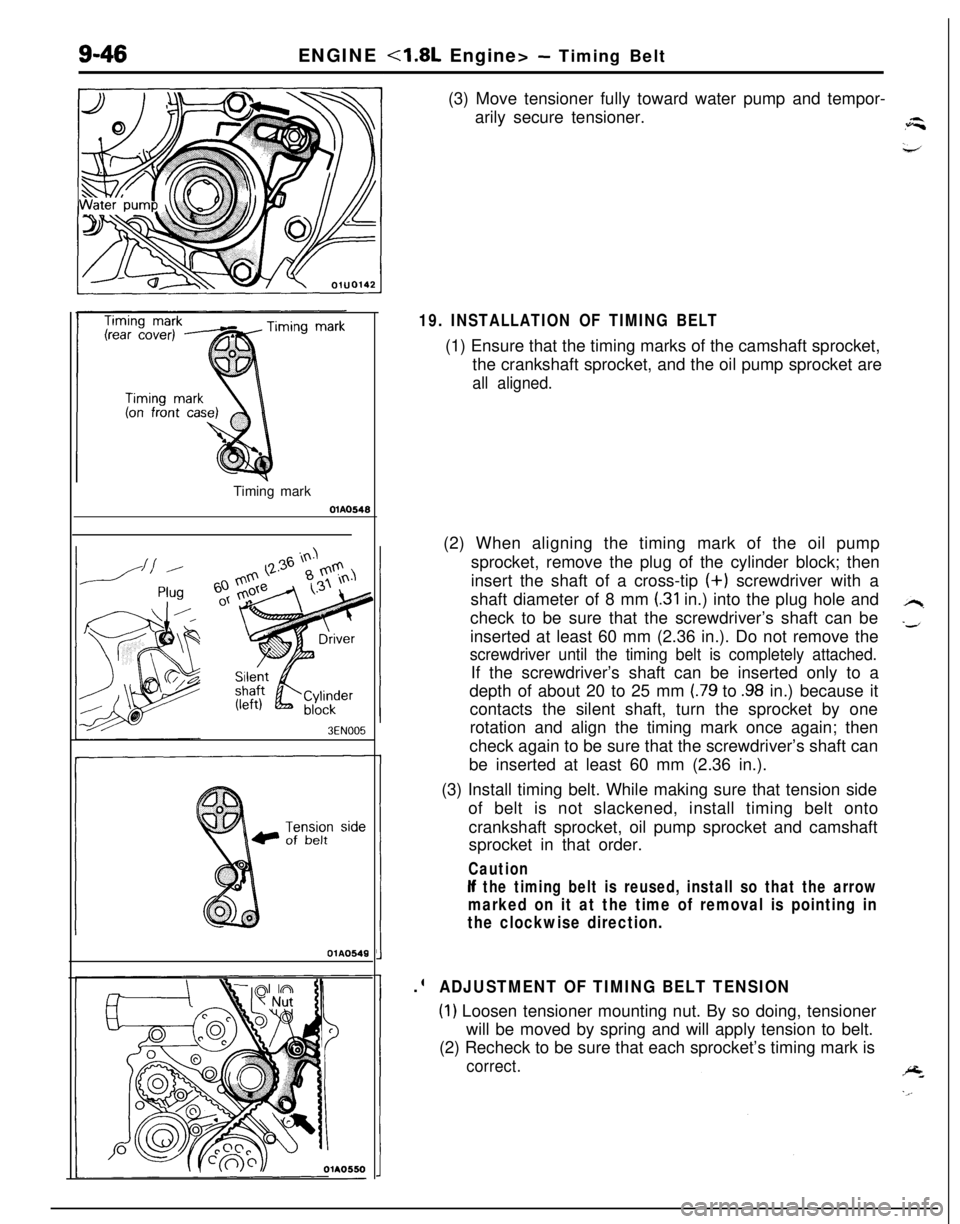
OlAO550-(3) Move tensioner fully toward water pump and tempor-
arily secure tensioner.
19. INSTALLATION OF TIMING BELT(1) Ensure that the timing marks of the camshaft sprocket,
the crankshaft sprocket, and the oil pump sprocket are
all aligned.(2) When aligning the timing mark of the oil pump
sprocket, remove the plug of the cylinder block; then
insert the shaft of a cross-tip (+) screwdriver with a
shaft diameter of 8 mm
(.31 in.) into the plug hole and
check to be sure that the screwdriver’s shaft can be
inserted at least 60 mm (2.36 in.). Do not remove the
screwdriver until the timing belt is completely attached.If the screwdriver’s shaft can be inserted only to a
depth of about 20 to 25 mm
(.79 to .98 in.) because it
contacts the silent shaft, turn the sprocket by one
rotation and align the timing mark once again; then
check again to be sure that the screwdriver’s shaft can
be inserted at least 60 mm (2.36 in.).
(3) Install timing belt. While making sure that tension side
of belt is not slackened, install timing belt onto
crankshaft sprocket, oil pump sprocket and camshaft
sprocket in that order.
Caution
If the timing belt is reused, install so that the arrow
marked on it at the time of removal is pointing in
the clockwise direction..
ADJUSTMENT OF TIMING BELT TENSION
(1) Loosen tensioner mounting nut. By so doing, tensioner
will be moved by spring and will apply tension to belt.
(2) Recheck to be sure that each sprocket’s timing mark is
correct.
Page 331 of 1216
ENGINE <1.8L Engine> - Timing Belt9-47
Timing mark
Nut
;olt diameter x lengthim (in.)
6x50(.23 x 1.97)
6
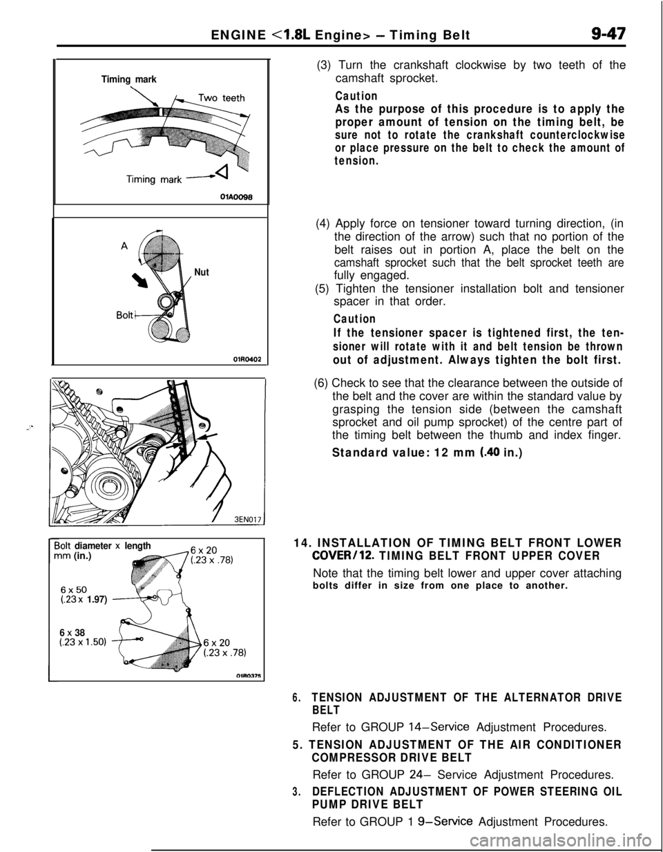
x 38(.23 x 1.50)(3) Turn the crankshaft clockwise by two teeth of the
camshaft sprocket.
Caution
As the purpose of this procedure is to apply the
proper amount of tension on the timing belt, be
sure not to rotate the crankshaft counterclockwise
or place pressure on the belt to check the amount of
tension.(4) Apply force on tensioner toward turning direction, (in
the direction of the arrow) such that no portion of the
belt raises out in portion A, place the belt on the
camshaft sprocket such that the belt sprocket teeth arefully engaged.
(5) Tighten the tensioner installation bolt and tensioner
spacer in that order.
Caution
If the tensioner spacer is tightened first, the ten-
sioner will rotate with it and belt tension be thrown
out of adjustment. Always tighten the bolt first.(6) Check to see that the clearance between the outside of
the belt and the cover are within the standard value by
grasping the tension side (between the camshaft
sprocket and oil pump sprocket) of the centre part of
the timing belt between the thumb and index finger.
Standard value: 12 mm (.40 in.)
14. INSTALLATION OF TIMING BELT FRONT LOWER
COVER/12. TIMING BELT FRONT UPPER COVERNote that the timing belt lower and upper cover attaching
bolts differ in size from one place to another.
6.TENSION ADJUSTMENT OF THE ALTERNATOR DRIVE
BELTRefer to GROUP
14-Service Adjustment Procedures.
5. TENSION ADJUSTMENT OF THE AIR CONDITIONER
COMPRESSOR DRIVE BELTRefer to GROUP
24- Service Adjustment Procedures.
3.DEFLECTION ADJUSTMENT OF POWER STEERING OIL
PUMP DRIVE BELTRefer to GROUP 1
g-Service Adjustment Procedures.