relay MITSUBISHI ECLIPSE 1991 Owner's Guide
[x] Cancel search | Manufacturer: MITSUBISHI, Model Year: 1991, Model line: ECLIPSE, Model: MITSUBISHI ECLIPSE 1991Pages: 1216, PDF Size: 67.42 MB
Page 255 of 1216
COOLING - Troubleshooting7A7
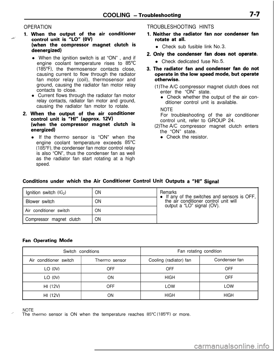
OPERATION
1. When the output of the air conditioner*--control unit is “LO” (OV)(when the
compressor magnet clutch isdeenergized)
l When the ignition switch is at “ON” , and if
engine coolant temperature rises to
85°C
(185”F), the thermosensor contacts close,
causing current to flow through the radiator
fan motor relay (coil), thermosensor and
ground, causing the radiator fan motor relay
contacts to close.
l Current flows through the radiator fan motor
relay contacts, radiator fan motor and ground,causing the radiator fan motor to rotate.
2. When the output of the air conditioner
control unit is “HI” (approx. 12V)(when the
compressor magnet clutch is
energized)l If the therm0 sensor is “ON” when the
engine coolant temperature exceeds
85°C
(185°F). the condenser fan motor control relay
is also “ON”, thus the condenser fan as well
as the radiator fan start rotating at a high
speed.
TROUBLESHOOTING HINTS
1. Neither the radiator fan nor condenser fanrotate at
all.l Check sub fusible link
No.3.
2. Only the condenser fan does not operate.l Check dedicated fuse
No.5.
3. The radiator fan and condenser fan do notoperate
in the low speed mode, but operateotherwise.
(1)The A/C compressor magnet clutch does not
enter the “ON” state.
l Check whether the output of the air con-
ditioner control unit is available.
NOTEFor troubleshooting of the air conditioner
control unit, refer to GROUP 24.
(2)The A/C compressor magnet clutch enters
the “ON” state.
l Check the resistor.Conditions
under which the Air Conditioner Control Unit Outputs a “HI” Signal
Ignition switch (IG2)
Blower switchAir conditioner switch
Compressor magnet clutch
ON
ON
ON
ON
Remarksl If any of the switches and sensors is OFF,
the air conditioner control unit will
output a “LO” signal (OV).
Fan Operating Mode
Switch conditions
Air conditioner switch
Therm0 sensor
LO
(OV)OFFLO
(OV)ONHI
(12V)OFFHI
(12V)ONFan rotating condition
Cooling (radiator) fanCondenser fan
OFFOFF
HIGHOFF
LOWLOW
HIGHHIGH
NOTE
_-The therm0 sensor is ON when the temperature reaches 85°C (185°F) or more.
Page 262 of 1216
7-14COOLING - Radiator
A
OFF
ON
h
--- ,
BWatertemperature
16v1100
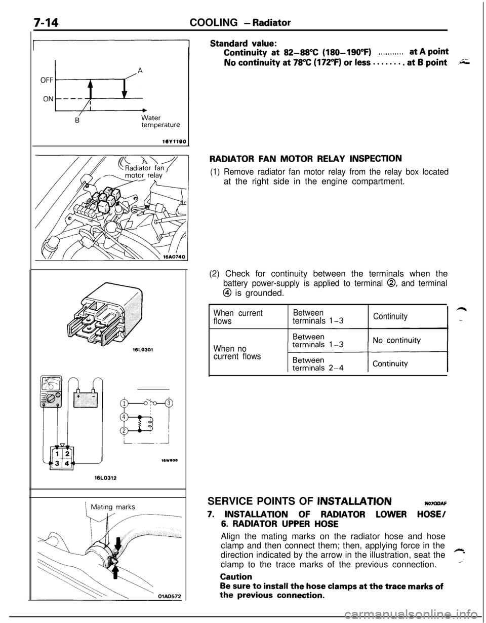
Standard value:Continuity
at 82-88X (180-190°F). . . . . . . . . . .at A pointNo continuity at
78°C (172°F) or less . . . . . . . . at 6 point.r;;;
RADIATOR FAN MOTOR RELAY INSPECTION
(1) Remove radiator fan motor relay from the relay box locatedat the right side in the engine compartment.
16LO312
1Mating marks(2) Check for continuity between the terminals when the
battery power-supply is applied to terminal 0, and terminal
@ is grounded.
When currentBetween
flowsterminals l-3Continuity
When no
current flowsSERVICE POINTS OF
JNSTALLATIONNOMDAF
7. INSTALLATION OF RADIATOR LOWER HOSE/
6. RADIATOR UPPER HOSEAlign the mating marks on the radiator hose and hose
clamp and then connect them; then, applying force in the
direction indicated by the arrow in the illustration, seat the
~
1clamp to the trace marks of the previous connection.Caution
Be sure to install the hose clamps at the trace marks ofthe
previous connection.
Page 455 of 1216
14-IFUEL SYSTEM
CONTENTS
AUTO-CRUISECONTROLSYSTEM...........................................109AUTO-CRUISECONTROL.......................................................140SERVICEADJUSTMENTPROCEDURES..............................135Accelerator Cable, Throttle Cable and Auto-cruise
ControlCableInspectionandAdjustment........................136Auto-cruise
ControlSystemInspection.............................135lndrvrdualPartsInspection..................................................137SPECIFICATIONS.....................................................................109GeneralSpecifications.......................................................109ServiceSpecifications
.........................................................109Torque Specrfications..........................................................109TROUBLESHOOTING...............................................................110Auto-CruiseControlCircurt................................................128Auto-cruise
ControlComponentsLocation........................126Auto-cruise Control Related Harnesses
.............................125Check Chart
........................................................................114Input Check.........................................................................123Self-diagnosis
Check..........................................................121Troubleshootrng
Quick-referenceChart..............................110ENGINECONTROL.......................................................................105ENGINECONTROL..................................................................107--SERVICEADJUSTMENTPROCEDURES..............................106Accelerator Cable Inspection and Adjustment..................106Accelerator Switch Inspectron and Adjustment................106SPECIFICATIONS.....................................................................105Lubricants.............................................................................105Sealant.................................................................................105ServiceSpecifications
..........................................................105TorqueSpecifications..........................................................105TROUBLESHOOTING...............................................................105FUELSYSTEM..............................................................................2FUELFILTER............................................................................104FUELLINEANDVAPORLINE..............................................102FUEL PUMP, FUEL GAUGE UNIT ANDOVERFILL LIMITER(TWO-WAY VALVE)
Switch........................................................64Air Conditioner Power Relay
..............................................67Components
Location......................................................56
ControlRelay
.................................................................66EGRControlSolenoidValve...............................................67EGRTemperatureSensor..................................................64Engine Coolant Temperature Sensor
.................................62IdlePosrtionSwitch
...........................................................63IdleSpeedControlServo
.............................
....................65InhibitorSwitch....................................................................65hjeCtOrS................................................................................65IntakeAirTemperatureSensor..........................................6’2MalfunctionlndtcatorLight
..........................................58MotorPosition
Sensor................................................63OxygenSensor
.................................................................64Power Steering 011 Pressure Swatch...........................65PowerTransistor
................................................................67PurgeControlSolenoidValve.........................................67
Self-Diagnosis.......................................................................
ThrottlePositronSensor.....................................................
Vehicle Speed Sensor.........................................................MPI
SYSTEMINSPECTION<2.0L DOHCEngine>...........Air Conditioner Power Relay..............................................
Arr Conditioner Swatch........................................................
Components Location
.........................................................
Control
Relay.......................................................................
EGR Control Solenoid Valve...............................................
EGR Temperature Sensor
...................................................
Engine Coolant Temperature Sensor
.................................Fuel Pressure Control Valve...............................................
Idle Position Switch
............................................................
Idle
SpeedControlServo...................................................Injectors
................................................................................
Intake Air Temperature Sensor..........................................
Malfunction Indicator Light.................................................
Oxygen Sensor
....................................................................
Power
Steering
OilPressureSwitch.................................Power Transistor
.................................................................
Purge Control Solenoid Valve.............................................
Self-Diaanosis.......................................................................
58
63
2382
79
688182
79
7682
77
79
79
76
727879
82
8273ThrottletiPosition Sensor
.....................................................77Vehicle Speed Sensor
.........................................................79SERVICE ADJUSTMENT PROCEDURES<1.8L Engine>........................................................................41Curb Idle Speed Inspection
................................................41EGR Valve Control Vacuum Check....................................47Fuel Pressure Test
..............................................................44Fuel Pump Operation Check
..............................................44Idle Speed Control and Throttle Position
Sensor Adjustment
..............................................................
41Purge Port Vacuum Check
.................................................47Release of Residual Pressure from
High Pressure Fuel Hose
...................................................
44Throttle
Body(Throttle Valve Area)Cleaning....................43SERVICE ADJUSTMENT PROCEDURES<2.0LDOHCEngine>............................................................48Basic Idle Speed Adjustment
.............................................
48
Curb Idle Speed Inspection
................................................48EGR Valve Control Vacuum Check....................................55Fuel Pressure Test
..............................................................52Fuel Pump Operation Check
..............................................51Idle Position Switch Adjustment........................................52Purge Port Vacuum Check
.................................................55Release of Residual Pressure from
High Pressure Fuel Hose
...................................................51Throttle Body (Throttle Valve Area) Cleaning....................51ThrottlePositionSensorAdjustment.................................50SPECIALTOOLS......................................................................6SPECIFICATIONS.....................................................................2GeneralSpecifications.........................................................2Sealant and Adhesive
.........................................................5Service Specifications
..........................................................4Torque Specifications
..........................................................5THROlTLEBODY<1.8LEngine>........................................85THROlTLE BODY <2.0L DOHC Engine>............................89TROUBLESHOOTING...............................................................6
Page 456 of 1216
14-2FUEL SYSTEM - Specifications
FUEL SYSTEM
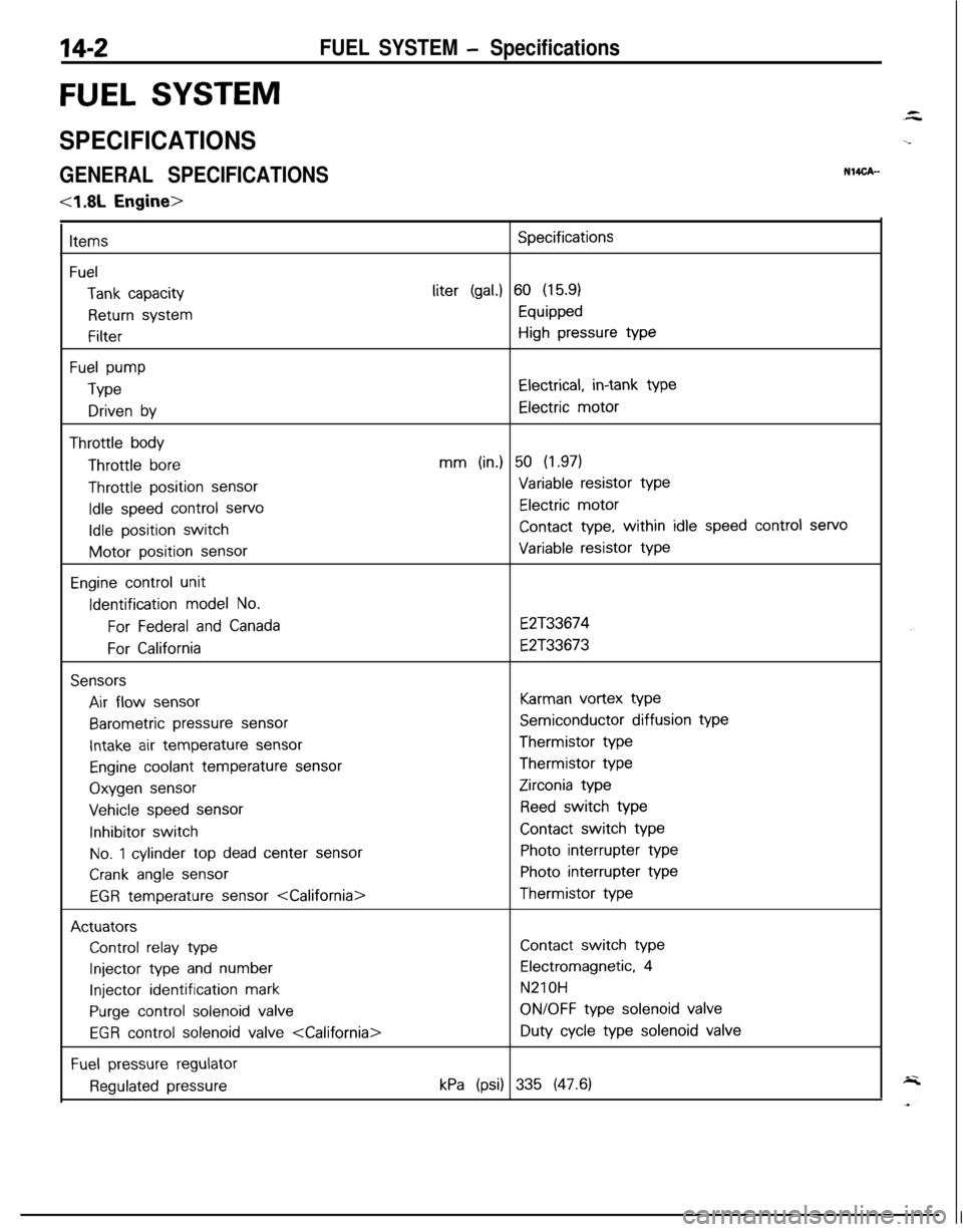
SPECIFICATIONS
GENERAL SPECIFICATIONSNW%-
4.8L Engine>
Items
Fuel
Tank capacity
Return system
Filter
Fuel pump
Type
Driven by
Throttle bodyThrottle
bore
Throttle position sensor
Idle speed control servo
Idle position switchMotor position
sensor
Engine control unitIdentification
model No.
For Federal and Canada
For California
SensorsAir flow
sensor
Barometric pressure sensor
Intake air temperature sensor
Engine coolant temperature sensorOxygen
sensor
Vehicle speed sensorInhibitor switch
No. 1 cylinder top dead center sensor
Crank angle sensor
EGR temperature sensor
Control relay type
Injector type and number
Injector identification mark
Purge control solenoid valve
EGR control solenoid valve
Fuel pressure regulator
Regulated pressure
Specificationsliter
(gal.) 60 (15.9)
Equipped
High pressure type
Electrical, in-tank type
Electric motor
mm (in.) 50 (1.97)
Variable resistor type
Electric motor
Contact type, within idle speed control servo
Variable resistor type
E2T33674
E2T33673
Karman vortex type
Semiconductor diffusion typeThermistor typeThermistor type
Zirconia type
Reed switch type
Contact switch type
Photo interrupter type
Photo interrupter typeThermistor type
Contact switch type
Electromagnetic, 4
N210H
ON/OFF type solenoid valveDuty
cycle type solenoid valve
kPa (psi) 335 (47.6)
Page 457 of 1216
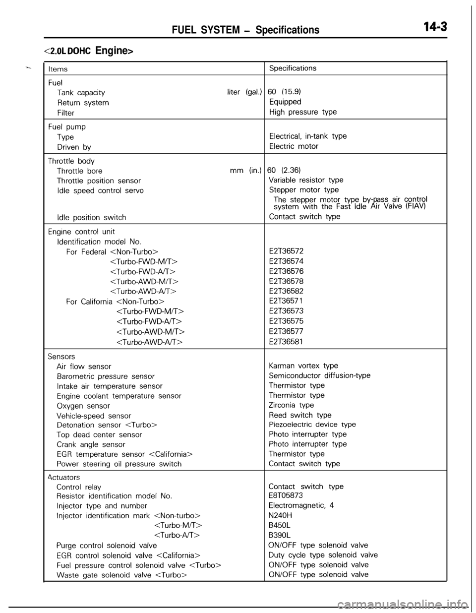
FUEL SYSTEM - Specifications14-3
<2.0L DOHC Engine>
ItemsSpecifications
Fuel
Tank capacityliter (gal.) 60 (15.9)
Return systemEquipped
FilterHigh pressure type
Fuel pump
TypeElectrical, in-tank type
Driven byElectric motor
Throttle bodyThrottle
boremm (in.) 60 (2.36)Throttle position
sensorVariable resistor type
Idle speed control servoStepper motor type
The stepper motor type by- ass air controlsystem with the Fast Idle6!rr Valve (FIAV)
Idle position switchContact switch type
Engine control unitIdentification
model No.
For Federal
E2T36574
E2T36576
E2T36578
E2T36582
For California
E2T36573
E2T36575
E2T36577
E2T36581
SensorsAir flow
sensorKarman vortex type
Barometric pressure sensorSemiconductor diffusion-type
Intake air temperature sensorThermistor type
Engine coolant temperature sensorThermistor type
Oxygen sensorZirconia type
Vehicle-speed sensorReed switch typeDetonation
sensor
Top dead center sensorPhoto interrupter type
Crank angle sensorPhoto interrupter type
EGR temperature sensor
Power steering oil pressure switchContact switch type4ctuators
Control relayContact switch type
Resistor identification model No.E8T05873
Injector type and numberElectromagnetic, 4
Injector identification mark
B450L
B390L
Purge control solenoid valveON/OFF type solenoid valve
EGR control solenoid valve
Fuel pressure control solenoid valve
gate solenoid valve
Page 461 of 1216
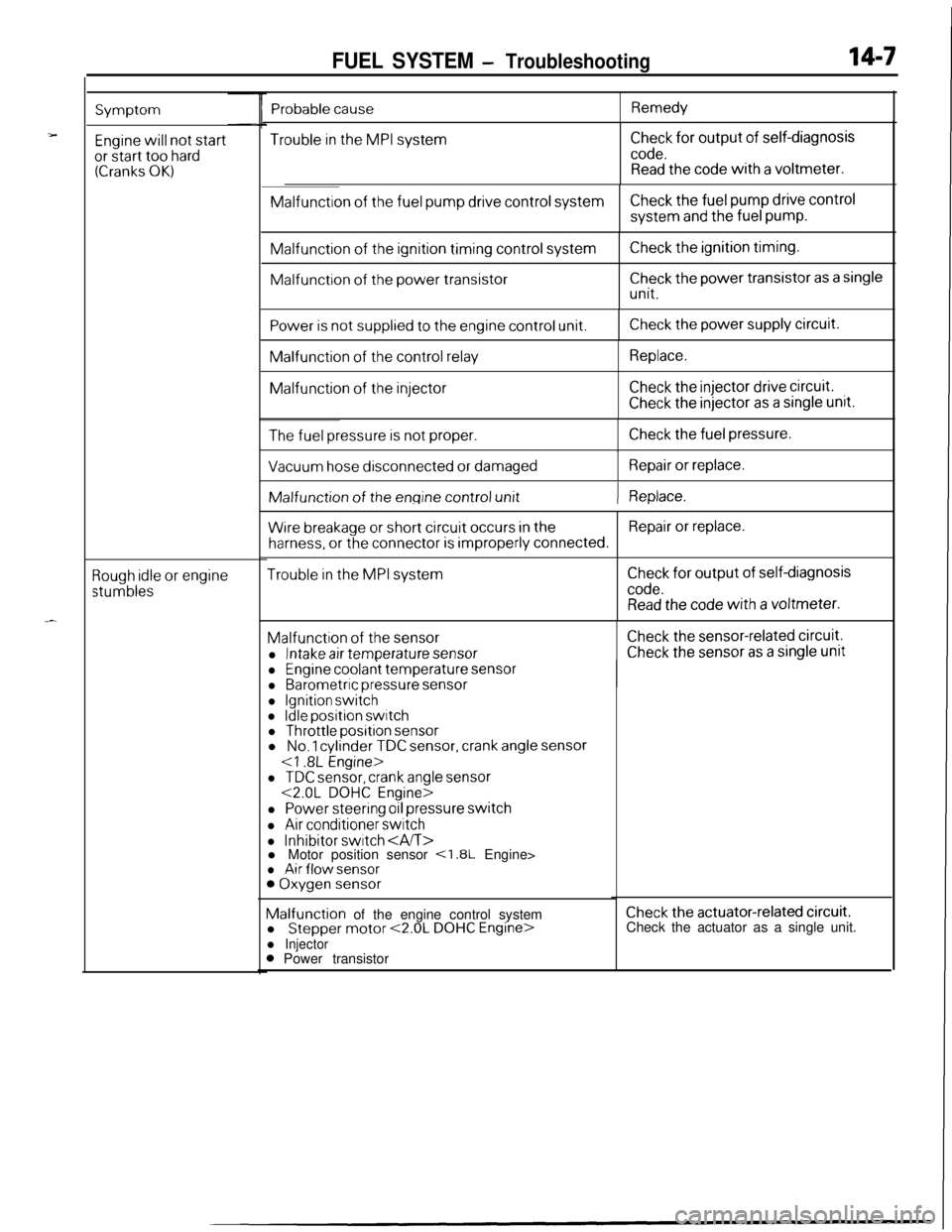
FUEL SYSTEM - Troubleshooting14-7
Symptom
Engine will not startor start too hard(Cranks OK)
Rough idle or engine
stumbles
Trouble in the MPI systemCheck for output of self-diagnosis
code.Read the code with a voltmeter.Malfunction
of the fuel pump drive control systemCheck the fuel pump drive controlsystem
and the fuel pump.Malfunction
of the ignition timing control systemMalfunction
of the power transistor
Check the ignition timing.
Check the power transistor as a single
unit.
Power is not supplied to the engine control unit.Check the power supply circuit.Malfunction
of the control relayMalfunction
of the injector
Replace.
Check the injector drive circuit.
Check the injector as a single unit.
The fuel pressure is not proper.Check the fuel pressure.
I
Vacuum hose disconnected or damagedRepair or replace.IMalfunction of
the engine control unit) Replace.
Wire breakage or short circuit occurs in theRepair or replace.
harness, or the connector is improperly connected.
Trouble in the MPI systemCheck for output of self-diagnosis
code.Read the code with a voltmeter.Malfunction
of the sensor
l Intake air temperature sensor
Check the sensor-related circuit.
Check the sensor as a single unit
Probable causeRemedy
l Engine coolant temperature sensorl Barometric pressure sensor
l Ignition switchl Idle position switchl Throttle position sensorl No. 1 cylinder TDC sensor, crank angle sensor
l TDC sensor, crank angle sensor<2.0L DOHC Engine>
l Power steering oil pressure switch
l Air conditioner switch
l Inhibitor switch l Motor position sensor <1.8L Engine>l Air flow sensor0 Oxygen sensorMalfunction of the engine control system
l
Stepper motor <2.0L DOHC Engine>l Injector0 Power transistor
Check the actuator-related circuit.Check the actuator as a single unit.
Page 462 of 1216
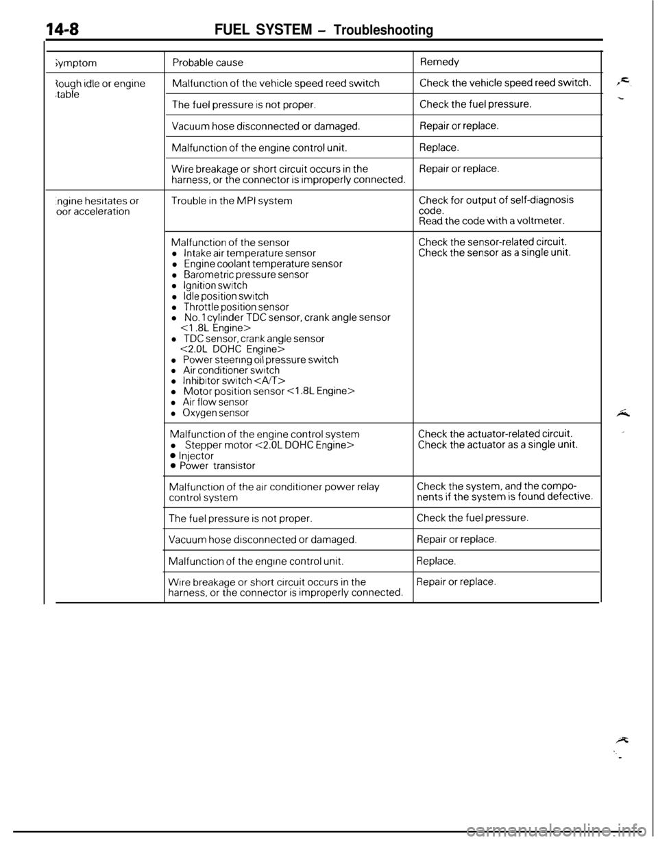
14-8FUEL SYSTEM - Troubleshootingiymptom
Probable causeMalfunction
of the vehicle speed reed switch
Remedy
Check the vehicle speed reed switch.
The fuel pressure is not proper.Check the fuel pressure.
Vacuum hose disconnected or damaged.Repair or replace.Malfunction
of the engine control unit.Replace.
Wire breakage or short circuit occurs in theRepair or replace.
harness, or the connector is improperly connected.
.ngine hesrtates oroor accelerationTrouble in the MPI systemCheck for output of self-diagnosiscode.Read the code with a voltmeter.
Malfunction of the sensorl Intake air temperature sensor
l Engine coolant temperature sensor
l Barometric pressure sensorl Ignition switch
l Idle position switchl Throttle position sensor
Check the sensor-related circuit.Check the sensor as a single unit.l
No. 1 cylinder TDC sensor, crank angle sensor
l TDC sensor, crank angle sensor<2.0L DOHC Engine>
l Power steering oil pressure switchl Air conditioner switchl Inhibitor switch l Motor position sensor
l Air flow sensor
l Oxygen sensorMalfunction
of the engine control system
l
Stepper motor <2.0L DOHC Engine>
0 Injector0 Power transistor
Check the actuator-related circuit.
Check the actuator as a single unit.Malfunction
of the air conditioner power relayCheck the system, and the compo-
control systemnents if the system is found defective.
The fuel pressure is not proper.Check the fuel pressure.
Vacuum hose disconnected or damaged.Repair or replace.Malfunction
of the engine control unit.Replace.
Wrre breakage or short circuit occurs in theRepair or replace.
harness, or the connector is improperly connected.
Page 464 of 1216
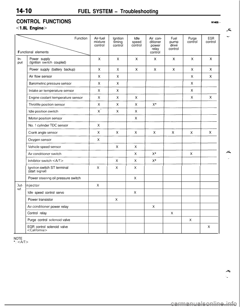
CONTROL FUNCTIONS
<1.8L Engine>
NWEEE- -
FunctionAir-fuelIgnitionIdleAir con-FuelPurgeEGRmixture
timingspeedditionercontrol
controlcontrolpower“d”,i2controlcontrol
relaycontrol
Functional elements
control
In-Power supplyXXXXXXX
Put(Ignition switch coupled)
Power supply (battery backup)
XXXXXXXAir flow sensor
XXXX
lgnitron switch ST terminalXXX(start srgnal)Power
steenng oil pressure switchX
Jut- InjectorXlutIdle speed control servoXPower transistor
X
Arr conditioner power relayX
Control relayX
Purge control solenord valveX
EGR control solenoid valveX
NOTE*:
FUEL SYSTEM - Troubleshooting
Page 465 of 1216
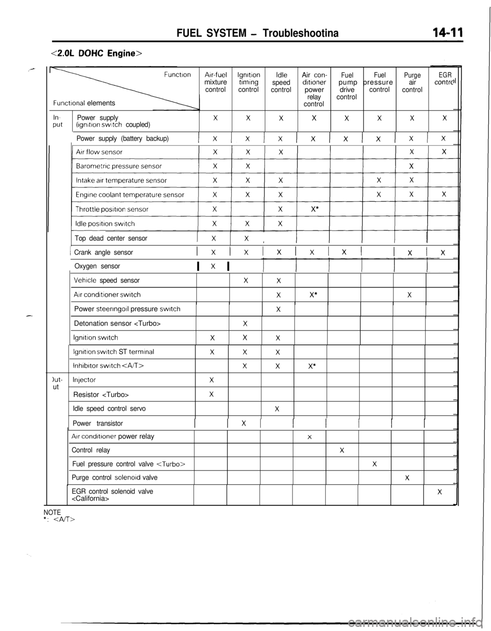
FUEL SYSTEM - Troubleshootina
<2.0LDOHC Engine>
FunctronArr-fuellgnrtronIdleAir con-
FuelFuel
PurgeEGRmixturetimrng
speeddrtronerpump pressureaircontrc
controlcontrol
controlpowerdrivecontrol
control
relaycontrol
Functronal elementscontrol
InPower supplyXXXXXXXXPut(ignrtron switch coupled)
Power supply (battery backup)
Ix Ix Ix lx lx lx lx Ix
Top dead center sensorI xXI
1 Crank angle sensorIxlxIxIxIxI lxlx
Oxygen sensorI x I
Vehrcle speed sensor
Air conditioner switch
XX
XX”XPower steering
011 pressure switchXIDetonation sensor
lgnrtron switch
X
XXX
lgnrtron switch ST terminalXXX
lnhibrtor switch XXX”
)ut-InjectorXutResistor
Idle speed control servoX
Power transistorI 1x1 I I I I I
Arr condrtroner power relay
Control relay
Fuel pressure control valve
Purge control solenord valve
X
X
X
X
EGR control solenoid valve
NOTE*:
Page 466 of 1216
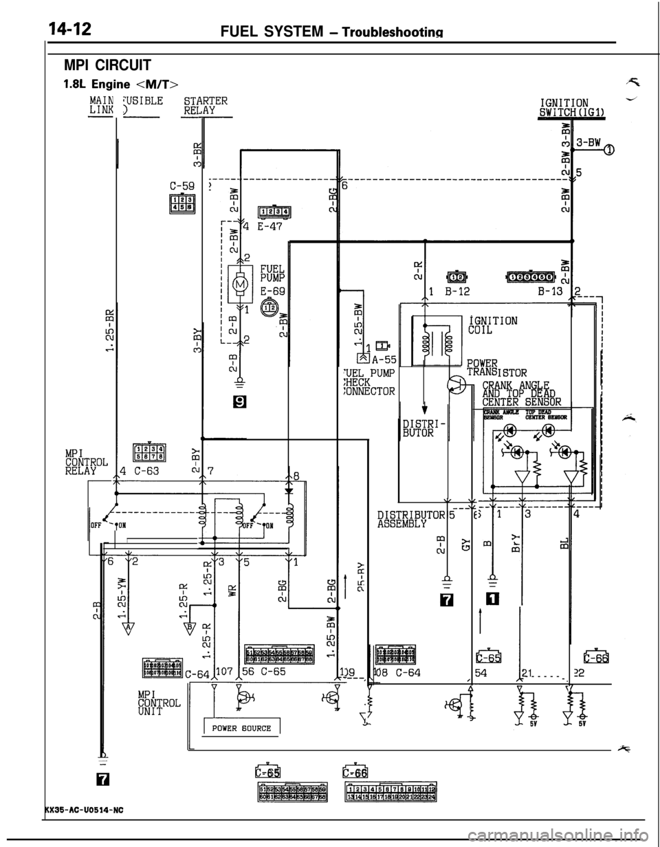
FUEL SYSTEM - Troubleshootinn
MPI CIRCUIT1.8L
Engine
VSIBLE3ST1REI--
IGNITIONSWITCHtIGl)
c-59
12s
m458
j;WKPUMP
:ONNECTOR
IGNITIONCOIL
ISTOR
CRANK ANGLAND TOP DE!iDCENTER SENSOR
\/---DISTRIBUTOR5ASSEMBLY
'pcuc
n
,L)‘E
;
6
b
E-
5
5
08 C-64/1
tci3j4
I21
------
-.Vr
MPICONTROLRELAY
r
I
h
Lkn
39‘---,
i
lsil12
iz;.
c-65a-66
135-AC-U0514-NC