relay MITSUBISHI ECLIPSE 1991 Workshop Manual
[x] Cancel search | Manufacturer: MITSUBISHI, Model Year: 1991, Model line: ECLIPSE, Model: MITSUBISHI ECLIPSE 1991Pages: 1216, PDF Size: 67.42 MB
Page 529 of 1216
FUEL SYSTEM - MPI Svstem InsDection <2.0L DOHC Engine>
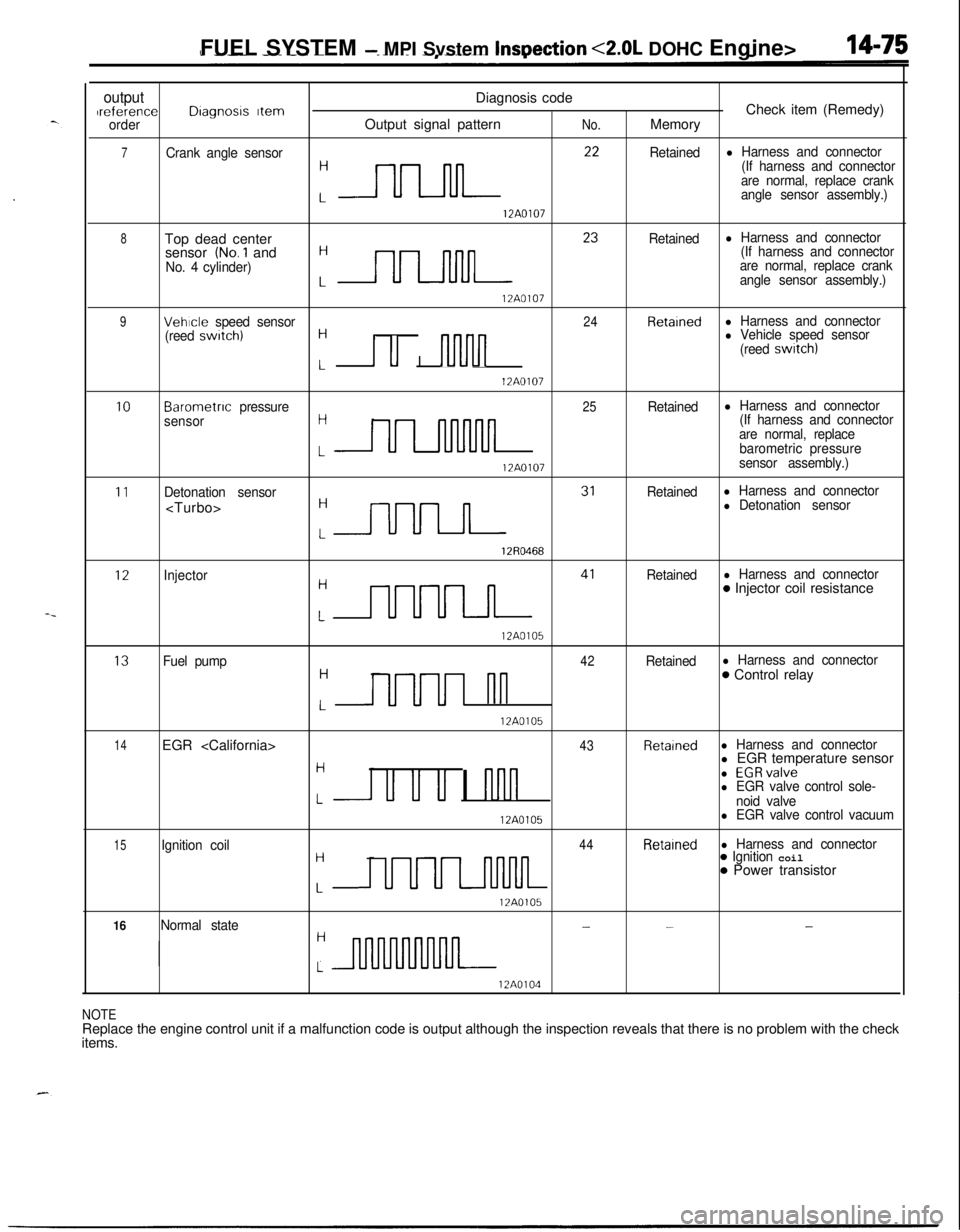
outputDiagnosis codeIreferenceDragnosrs ItemCheck item (Remedy)orderOutput signal patternNo.Memory
7Crank angle sensor
:nn **
Retainedl Harness and connector
(If harness and connector
are normal, replace crank
angle sensor assembly.)
12A0107
8Top dead center
:- 23
Retainedl Harness and connectorsensor (No.1 and(If harness and connector
No. 4 cylinder)are normal, replace crank
angle sensor assembly.)
12A0107
9Vehicle speed sensor24Retainedl Harness and connector
(reed swatch)H
I u I nlvln
l Vehicle speed sensor
(reed switch)
L12A0107
10Barometnc pressure25Retainedl Harness and connector
sensorH(If harness and connector
are normal, replace
LULllnMllbarometric pressure
12A0107sensor assembly.)
11Detonation sensorRetainedl Harness and connector
:m 31
l Detonation sensor
12R0468
12Injector
:m 41
Retainedl Harness and connector0 Injector coil resistance
12A0105
13Fuel pump42Retainedl Harness and connectorH
UUUI nn
0 Control relay
L12A0105
14EGR
Hl EGR temperature sensor
u u u I nnn
l EGRvalvel EGR valve control sole-Lnoid valve
12A0105l EGR valve control vacuum
15Ignition coil44Retainedl Harness and connectorH
UUUL-llMlL
0 Ignition coil0 Power transistor
L12A0105
16Normal state---H
L
12A0104
NOTEReplace the engine control unit if a malfunction code is output although the inspection reveals that there is no problem with the check
items.
Page 535 of 1216
_-
FUEL SYSTEM - MPI System Inspection <2.0L DOHC Engine>'I4181
OlLO22Z
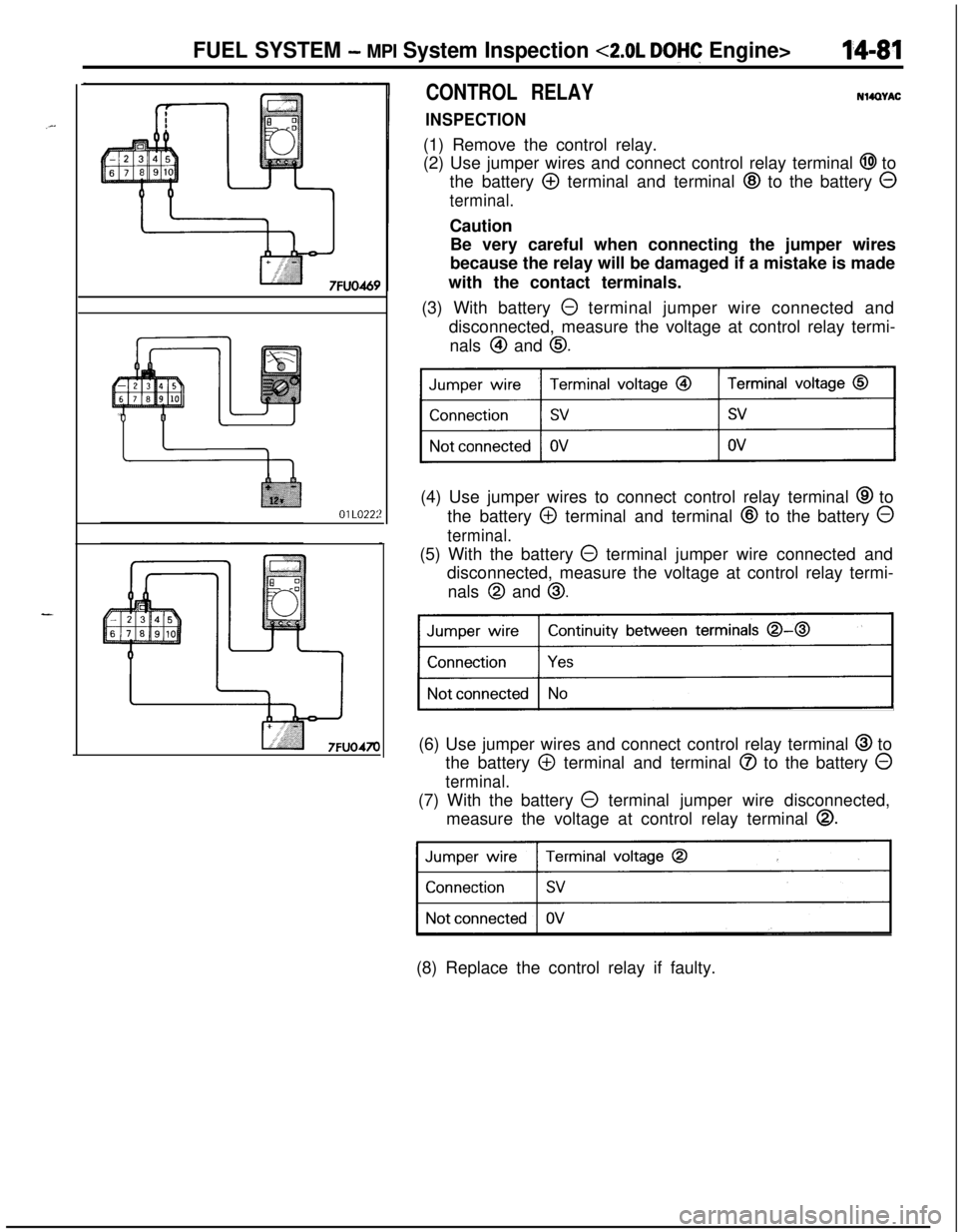
CONTROL RELAY
INSPECTIONNWWAC
(1) Remove the control relay.
(2) Use jumper wires and connect control relay terminal
@I to
the battery
@ terminal and terminal @ to the battery 0
terminal.Caution
Be very careful when connecting the jumper wires
because the relay will be damaged if a mistake is made
with the contact terminals.
(3) With battery
0 terminal jumper wire connected and
disconnected, measure the voltage at control relay termi-
nals
@I and 0.(4) Use jumper wires to connect control relay terminal
@ to
the battery
@ terminal and terminal @ to the battery 0
terminal.(5) With the battery
@ terminal jumper wire connected and
disconnected, measure the voltage at control relay termi-
nals
@I and 0.
Continuity between terminals 0-0
)(6) Use jumper wires and connect control relay terminal
@ to
the battery
@ terminal and terminal @ to the battery 0
terminal.(7) With the battery
0 terminal jumper wire disconnected,
measure the voltage at control relay terminal
0.
31(8) Replace the control relay if faulty.
Page 536 of 1216
14-82FUEL SYSTEM - MPI System Inspection <2.0L DOHC Engine>
\ \\I \3FUO352
,\ \
\I \3FUO353
,\ ‘\R/
\ \\I \3FUo354
POWER TRANSISTORRefer to GROUP 8
- Ignition System
NlIAcQAl
a-4
AIR CONDITIONER POWER RELAYN14NCl.a -Refer to GROUP 24
- Air Conditioner.
PURGE CONTROL SOLENOID VALVEN14RCKARefer to GROUP 25
- Evaporative Emission Control System.
EGR CONTROL SOLENOID VALVE
N14NCURefer to GROUP 25
- Exhaust Gas Recirculation System.
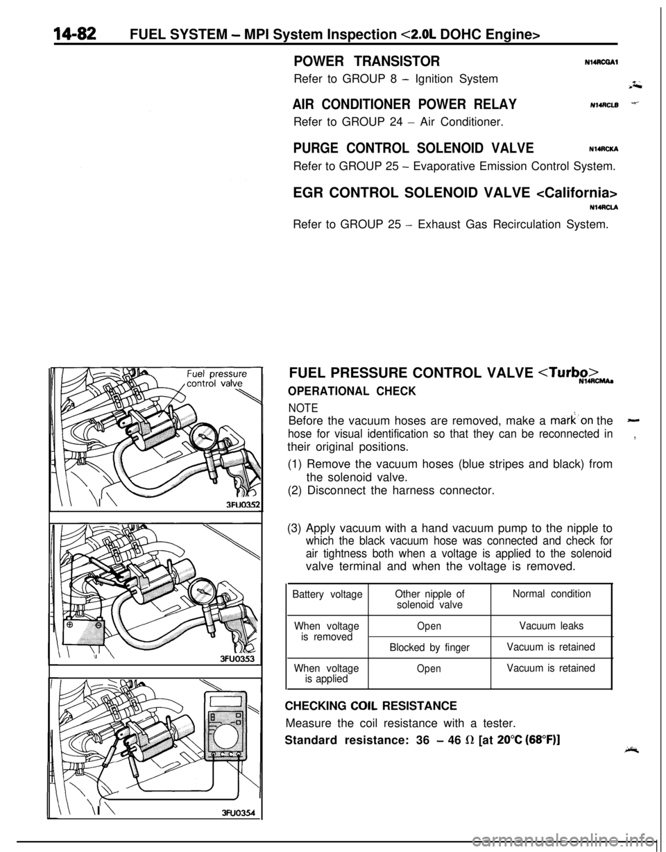
FUEL PRESSURE CONTROL VALVE
NOTEBefore the vacuum hoses are removed, make a mark’on the
-
hose for visual identification so that they can be reconnected in,their original positions.
(1) Remove the vacuum hoses (blue stripes and black) from
the solenoid valve.
(2) Disconnect the harness connector.
(3) Apply vacuum with a hand vacuum pump to the nipple to
which the black vacuum hose was connected and check for
air tightness both when a voltage is applied to the solenoidvalve terminal and when the voltage is removed.
Battery voltageOther nipple of
solenoid valveNormal condition
When voltage
is removed
When voltage
is applied
OpenVacuum leaks
Blocked by fingerVacuum is retained
OpenVacuum is retainedCHECKING
COIL RESISTANCE
Measure the coil resistance with a tester.
Standard resistance: 36
- 46 R [at 20°C (68”F)]
Page 571 of 1216
i-._AUTO-CRUISE CONTROL SYSTEM
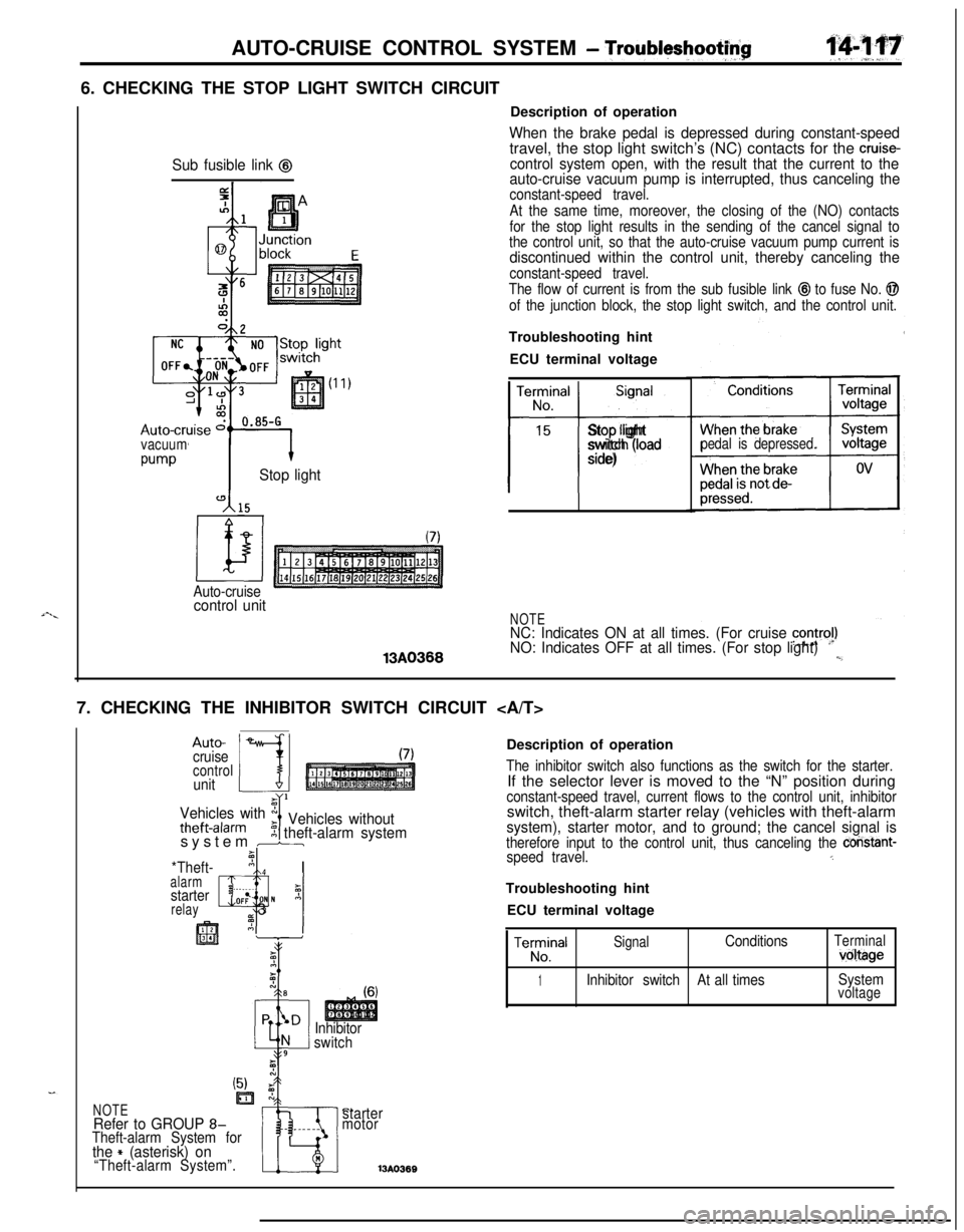
- Troubltyshootf$6. CHECKING THE STOP LIGHT SWITCH CIRCUIT
Sub fusible link @
vacuum
w-vStop light
Auto-cruisecontrol unit13A0366Description of operation
When the brake pedal is depressed during constant-speedtravel, the stop light switch’s (NC) contacts for the cruise-control system open, with the result that the current to the
auto-cruise vacuum pump is interrupted, thus canceling the
constant-speed travel.
At the same time, moreover, the closing of the (NO) contacts
for the stop light results in the sending of the cancel signal to
the control unit, so that the auto-cruise vacuum pump current is
discontinued within the control unit, thereby canceling the
constant-speed travel.
The flow of current is from the sub fusible link
@I to fuse No. @
of the junction block, the stop light switch, and the control unit.Troubleshooting hint
ECU terminal voltage
TerminalSignal
No.
15
t-i-
Stop light
switch (load
side)pedal is depressed.
NOTENC: Indicates ON at all times. (For cruise contra!)NO: Indicates OFF at all times. (For stop light)l,_7. CHECKING THE INHIBITOR SWITCH CIRCUIT
Auto-
cruise
controlunit
Vehicles with x
theft-alarmIVehicles without5 theft-alarm systemsystem br
*Theft-’ nI Ialarm, ._I
starterz
relayQlOF: N A_ 3
Inhibitor
switchDescription of operation
The inhibitor switch also functions as the switch for the starter.If the selector lever is moved to the “N” position during
constant-speed travel, current flows to the control unit, inhibitorswitch, theft-alarm starter relay (vehicles with theft-alarm
system), starter motor, and to ground; the cancel signal istherefore input to the control unit, thus canceling the constant-speed travel.5Troubleshooting hint
ECU terminal voltage
TeE!alSignalConditionsTerminalvoltage
1Inhibitor switchAt all timesSystemvoltage
C.starter
motor13A036BNOTERefer to GROUP 8-Theft-alarm System forthe + (asterisk) on“Theft-alarm System”.
Page 877 of 1216
AUTOMATIC TRANSAXLE - Troubleshooting214%3
TRANSAXLE CONTROL UNIT
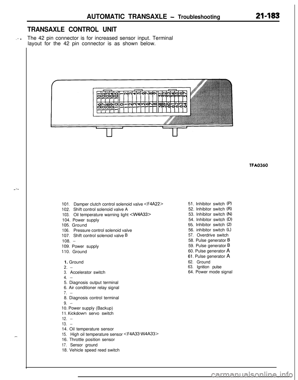
-‘” .The 42 pin connector is for increased sensor input. Terminal
layout for the 42 pin connector is as shown below.TFA0360
101.Damper clutch control solenoid valve
102.Shift control solenoid valve A
103.Oil temperature warning light
105. Ground
106.Pressure control solenoid valve
107.Shift control solenoid valve B108.
-
109. Power supply
110. Ground
1. GroundL.
-
3.Accelerator switch
4.-5. Diagnosis output terminal
6. Air conditioner relay signal
7.-8. Diagnosis control terminal
9.-
IO. Power supply (Backup)
11. Kickdown servo switch
12.-
13.-14. Oil temperature sensor
15.High oil temperature sensor
16. Throttle position sensor
17.Sensor ground18. Vehicle speed reed switch
51. Inhibitor switch (PI52. Inhibitor switch
(8)53. Inhibitor switch
(N)54. Inhibitor switch
(D)
55. Inhibitor switch (2)56. inhibitor switch
(L)
57.Overdrive switch
58. Pulse generator
B59. Pulse generator
B60. Pulse generator A
61. Pulse generator A
62.Ground63.Ignition pulse64. Power mode signal
Page 896 of 1216
21-202AUTOMATIC TRANSAXLE - Troubleshooting
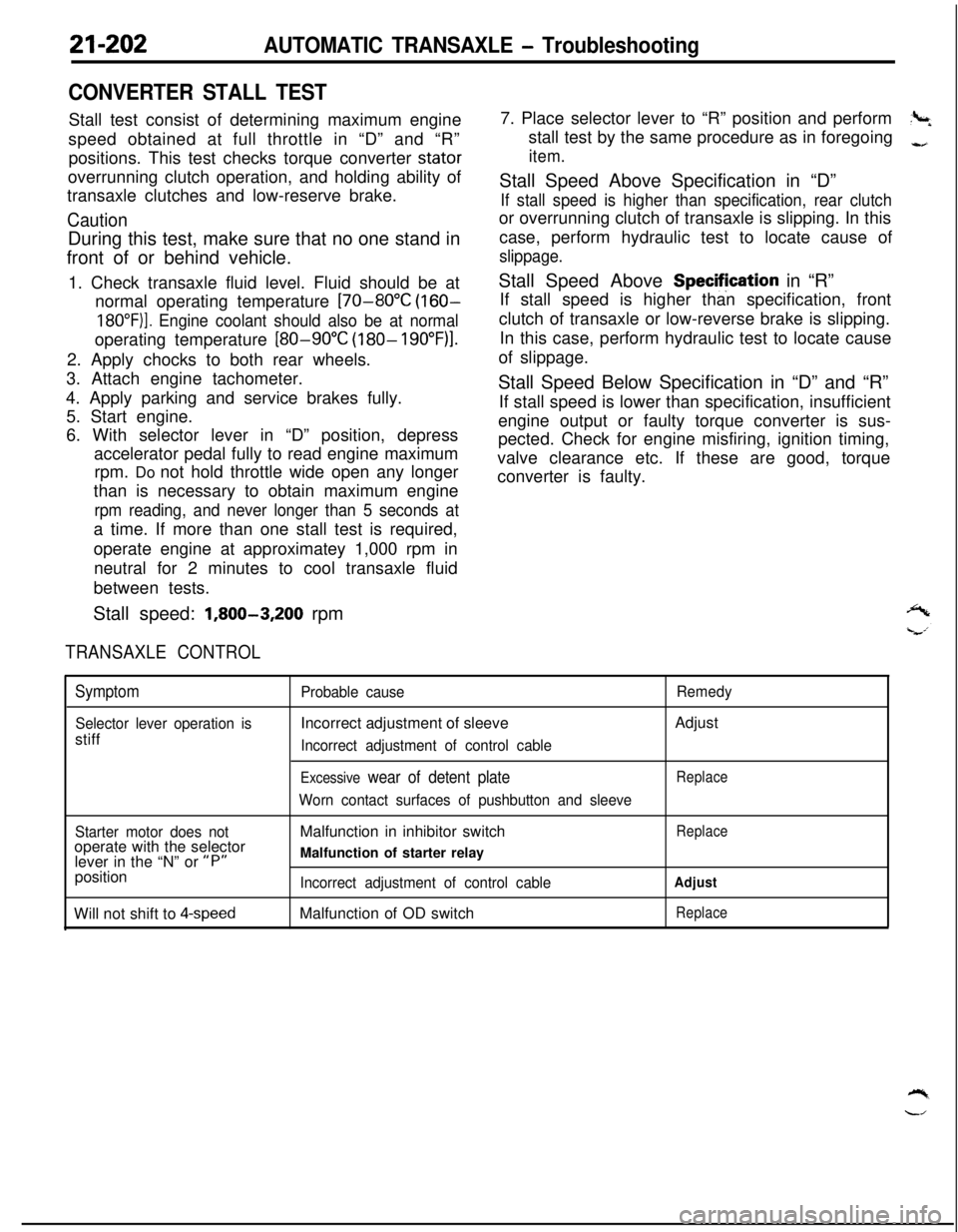
CONVERTER STALL TESTStall test consist of determining maximum engine
speed obtained at full throttle in “D” and “R”
positions. This test checks torque converter stator
overrunning clutch operation, and holding ability of
transaxle clutches and low-reserve brake.
CautionDuring this test, make sure that no one stand in
front of or behind vehicle.
1. Check transaxle fluid level. Fluid should be at
normal operating temperature
[70-80°C (160-
18O”F)]. Engine coolant should also be at normaloperating temperature
[80-90°C (180- 19O”F)l.2. Apply chocks to both rear wheels.
3. Attach engine tachometer.
4. Apply parking and service brakes fully.
5. Start engine.
6. With selector lever in “D” position, depress
accelerator pedal fully to read engine maximum
rpm. Do not hold throttle wide open any longer
than is necessary to obtain maximum engine
rpm reading, and never longer than 5 seconds ata time. If more than one stall test is required,
operate engine at approximatey 1,000 rpm in
neutral for 2 minutes to cool transaxle fluid
between tests.
Stall speed:
1,800-3,200 rpm
TRANSAXLE CONTROL7. Place selector lever to “R” position and perform
?+stall test by the same procedure as in foregoing
-,
item.Stall Speed Above Specification in “D”
If stall speed is higher than specification, rear clutchor overrunning clutch of transaxle is slipping. In this
case, perform hydraulic test to locate cause of
slippage.Stall Speed Above Specifjcation in “R”
If stall speed is higher than specification, front
clutch of transaxle or low-reverse brake is slipping.
In this case, perform hydraulic test to locate cause
of slippage.
Stall Speed Below Specification in “D” and “R”
If stall speed is lower than specification, insufficient
engine output or faulty torque converter is sus-
pected. Check for engine misfiring, ignition timing,
valve clearance etc. If these are good, torque
converter is faulty.
Symptom
Selector lever operation isstiff
Probable causeIncorrect adjustment of sleeve
Incorrect adjustment of control cable
Excessive wear of detent plate
Worn contact surfaces of pushbutton and sleeveRemedyAdjust
Replace
Starter motor does notoperate with the selector
lever in the “N” or
“P”position
Will not shift to
4-speedMalfunction in inhibitor switch
Malfunction of starter relay
Incorrect adjustment of control cableMalfunction of OD switch
Replace
Adjust
Replace
Page 1046 of 1216
23-2
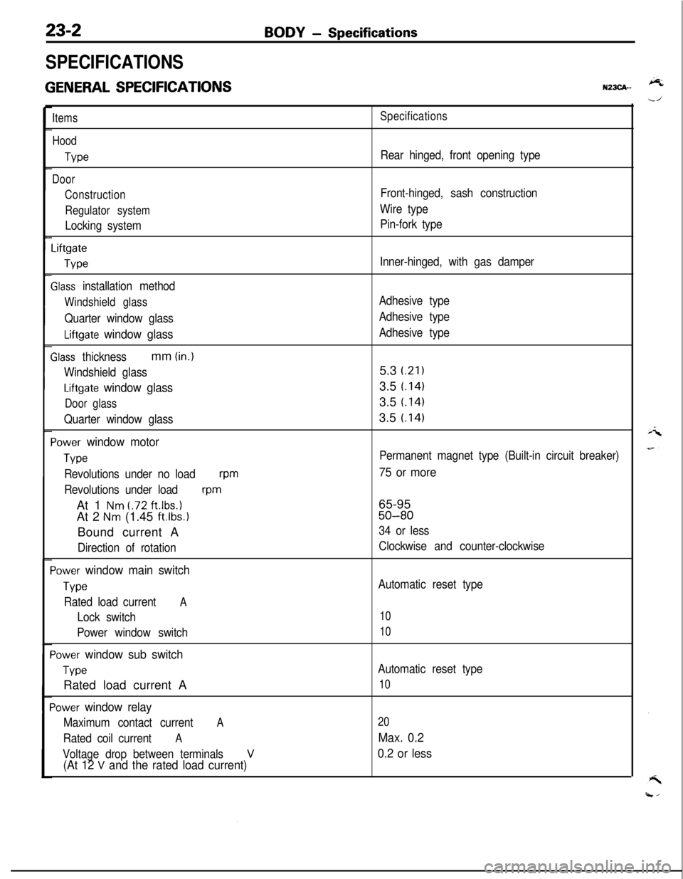
SPECIFICATIONS
GENERAL SPECIFICATIONS
BODY - Specifications
N23CA--
Items
Hood
We
Door
Construction
Regulator system
Locking system
Liftgate
We
Slass installation method
Windshield glass
Quarter window glass
Liftgate window glass
Zlass thicknessmm (in.)
Windshield glass
Liftgate window glass
Door glass
Quarter window glass
‘ower window motor
Type
Revolutions under no loadwm
Revolutions under load
wmAt 1
Nm t.72 ft.lbs.1At 2
Nm (1.45 ft.lbs.1Bound current A
Direction of rotation
‘ower window main switch
Type
Rated load currentA
Lock switch
Power window switch
‘ower window sub switch
TvwRated load current A
‘ower window relay
Maximum contact currentA
Rated coil currentA
Voltage drop between terminalsV(At 12 V and the rated load current)
Specifications
Rear hinged, front opening type
Front-hinged, sash construction
Wire type
Pin-fork type
Inner-hinged, with gas damper
Adhesive type
Adhesive type
Adhesive type5.3
i.21)3.5
t.1413.5
t.1413.5
t.141
Permanent magnet type (Built-in circuit breaker)
75 or more65-95
50-80
34 or less
Clockwise and counter-clockwise
Automatic reset type
10
10
Automatic reset type
10
20
Max. 0.2
0.2 or less
Page 1047 of 1216
BODY - Specifications23-3
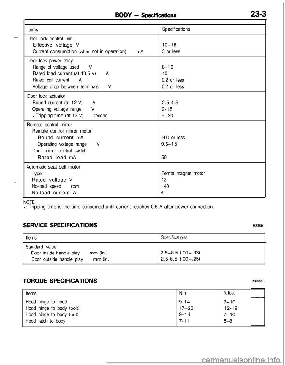
Items
Door lock control unitEffective voltage
V
Current consumption (when not in operation)
Door lock power relay
Range of voltage used
V
Rated load current (at 13.5 VIA
Rated coil currentA
Voltage drop between terminalsV
Door lock actuator
Bound current (at 12 VIA
Operating voltage rangeV
l Tripping time (at 12 V)second
Remote control mirror
Remote control mirror motorBound current
mA
Operating voltage range
V
Door mirror control switchRated load
mA
4utomatic seat belt motor
TypeRated voltage
V
No-load speedwmNo-load current A
mASpecifications
lo-16
3 or less8-16
10
0.2 or less
0.2 or less2.5-4.5
9-15
5-30
500 or less
9.5-l 5
50
Ferrite magnet motor
12
140
4
NOTEl : Tripping time is the time consumed until current reaches 0.5 A after power connection.
SERVICE SPECIFICATIONSN23CB--
ItemsSpecifications
Standard valueDoor
inside handle playmm (in.)2.5-8.5 (.09-,331
Door outside handle playmm (in.)2.5-6.5 (.09-.25)
TORQUE SPECIFICATIONS
ItemsNmft.lbs.
Hoodhingetohood9-14
7-10
Hoodhingetobody(bolt)17-2612-19
Hoodhingetobody(nut)9-147-10
Hoodlatchtobody7-115-8
Page 1054 of 1216
23-10BODY - Troubleshooting
(PABBENGER’B BIDE)v 1
E-51
‘S
E-05
I2
m3458
POWER WINDOW
MOTOR
E-04
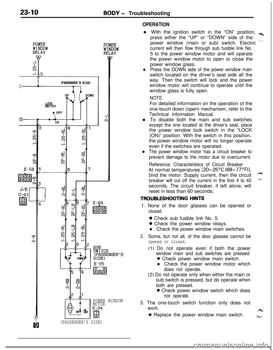
OPERATIONl With the ignition switch in the “ON” position,
rs;,press either the “UP” or “DOWN” side of the
power window (main or sub) switch. Electric
-*
current will then flow through sub fusible link No.5 to the power window motor and will operate
the power window motor to open or close the
power window glass.
lPress the DOWN side of the power window mainswitch located on the driver’s seat side all the
way. Then the switch will lock and the power
window motor will continue to operate until the
window glass is fully open.
NOTEFor detailed information on the operation of the
one-touch down (open) mechanism, refer to the
Technical Information Manual.l To disable both the main and sub switches
except the one located at the driver’s seat, placethe power window lock switch in the “LOCK
(ON)” position. With the switch in this position,
the power window motor will no longer operate
even if the switches are operated.
lThe power window motor has a circuit breaker to
prevent damage to the motor due to overcurrent.
Reference: Characteristics of Circuit BreakerAt normal temperatures
[ZO-25OC (68-77”F)I,bind the motor. Supply current, then the circuit
h
breaker will cut off the current in the first 4 to 40\&’seconds. The circuit breaker, if left alone, will
reset in less than 60 seconds.
TROUBLESHOOTING HINTS1. None of the door glasses can be opened or
closed.0 Check sub fusible link No. 5.0 Check the power window relays.
l Check the power window main switches.
2.Some, but not all, of the door glasses cannot be
opened or closed.
(I) Do not operate even if both the power
window main and sub switches are pressed.0 Check power window main switch.
l Check the power window motor which
does not operate.
(2) Do not operate only when either the main or
sub switch is pressed, but do operate when
both are pressed.0 Check power window switch which does
not operate.3. The one-touch switch function only does not
work.A0 Replace the power window main switch.
w
(PASSENGER'S SIDE)
Page 1057 of 1216
BODY - Troubleshooting23-13
OPERATION
TROUBLESHOOTING HINTS
-.l If the inside lock knobs of the doors are placedin the LOCK (or UNLOCK) position, the switch inthe door lock actuator will be “OFF” (or “ON”),
and the output transistor will be “ON” for 0.5
second according to the timer function in the
door lock control unit (or theft-alarm control unit).As a result, the LOCK side (or UNLOCK side) of
the door lock relay will be “ON”, operating the
actuators of all of the doors.
NOTE
The door lock actuator contains a PTC thermistor
to prevent damage caused by overheating of the
motor. If the central door lock is frequently used,the actuator may temporarily fail to operate. If it
returns to normal in a few minutes, it is not
defective.
1.
2.One of the door lock actuators fails to operate.
l Check the door actuator which fails to
operate.Cannot be placed in the LOCK or UNLOCK
position by the inside lock knob on either driver’s
or front passenger’s seat side.0 Check the switch in the actuator.0 Check the door lock control unit (or
theft-alarm control unit).
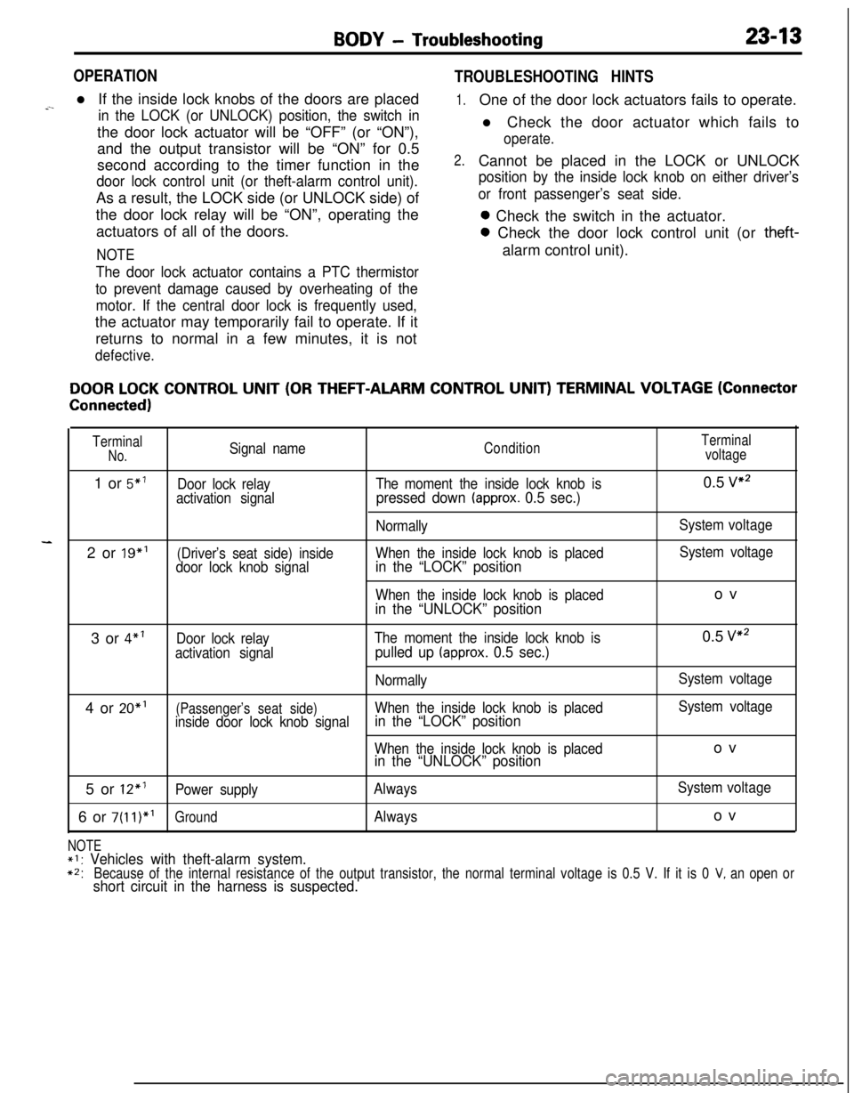
DOOR LOCK CONTROL UNIT (OR THEFT-ALARM CONTROL UNIT) TERMINAL VOLTAGE (Connector
Connected)
TerminalSignal nameConditionTerminalNo.voltage1 or
5”’Door lock relayThe moment the inside lock knob is0.5 vs2
activation signal
pressed down (approx. 0.5 sec.)
NormallySystem voltage2 or 19”’
(Driver’s seat side) insideWhen the inside lock knob is placedSystem voltage
door lock knob signalin the “LOCK” position
When the inside lock knob is placedov
in the “UNLOCK” position3 or
4”’Door lock relayThe moment the inside lock knob is0.5 v2
activation signalpulled up (approx. 0.5 sec.)
NormallySystem voltage4 or 20”’
(Passenger’s seat side)When the inside lock knob is placedSystem voltage
inside door lock knob signalin the “LOCK” position
When the inside lock knob is placedovin the “UNLOCK” position5 or
12*’Power supplyAlwaysSystem voltage6 or
7(11)*’GroundAlwaysov
NOTE*I: Vehicles with theft-alarm system.
*2:Because of the internal resistance of the output transistor, the normal terminal voltage is 0.5 V. If it is 0 V, an open orshort circuit in the harness is suspected.